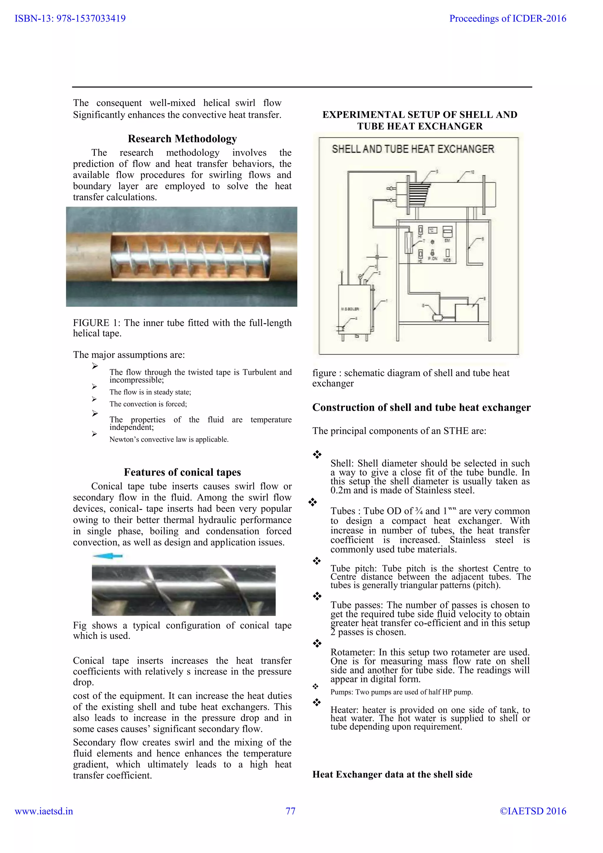
Heat Transfer Enhancement of Shell and Tube Heat Exchanger
Using Conical Tapes
M.Dinesh kumar1
, B.Karthikeyan2, A.Govindaraj3, K.Dhanasekaran4
1,2,3,4
B.E students, Department of Mechanical Engineering,
Jayalakshmi Institute of Technoogy, Thoppur, Dharmapuri-636 352
Abstract:
This paper provides heat transfer and friction factor data for single -phase flow in a shell and tube heat
exchanger fitted with a helical tape insert. In the double concentric tube heat exchanger, hot air was passed
through the inner tube while the cold water was flowed through the annulus. The influences of the helical insert
on heat transfer rate and friction factor were studied for counter flow, and Nusselt numbers and friction factor
obtained were compared with previous data (Dittus 1930, Petukhov 1970, Moody 1944) for axial flows in the
plain tube. The flow considered is in a low Reynolds number range between 2300 and 8800. A maximum
percentage gain of 165% in heat transfer rate is obtained for using the helical insert in comparison with the plain
tube.
Keywords: enhancement heat transfer, swirl flow devices, a helical tape insert
I. Introduction
In the past decade, heat transfer enhancement
technology has been developed and widely applied to
heat exchanger applications; for example,
refrigeration, automotive, process industry, solar
water heater, etc. The aim of augmentative heat
transfer is to accommodate high heat fluxes (or heat
transfer coefficient). Up to the present there has been
a great attempt to reduce the sizes and cost of the heat
exchanger, and energy consumption. The most
significant variable in reducing the size and the cost
of the heat exchanger, which generally leads to less
capital cost and another advantage, is reduction of the
temperature driving force, which increases the second
law efficiency and decreases the entropy generation.
Thus, this captivates the interests of the number of
researchers. The great attempt on utilizing different
methods is to increase the heat transfer rate through
the compulsory force convection. Meanwhile, it is
found that this way can reduce the sizes of the heat
exchanger device and save up the energy. In general,
enhancing the heat transfer can be divided into two
groups: One is the passive method; it is the way
without being stimulated by the external power such
as surface coatings, rough surfaces, extended
surfaces, the swirl flow devices, the convoluted
(twisted) tube, additives for liquid and gases. The
other is the active method. This way requires the
extra external power sources, for example mechanical
aids, surface-fluid vibration, the injection and the
suction of the fluid, the jet impingement, and the
electrostatic fields.
The swirl flow devices can be classified into two
kinds: the first is the continuous swirl flow and the
other is the decaying swirl flow. For the continuous
swirl flow, the swirling motion persists over the
whole length of the tube for example twisted tape
inserts [1,2], coiled wires inserted along the whole
tube [3] and helical grooves in the inner surface of
tube generate, while in the decaying swirl flow, the
swirl is generated at the entrance of the tube and
decays along the flow path for example the radial
guide vane swirl generator and the tangential flow
injection device [4,5,6,7,8]. For the decaying swirl
flow, the heat transfer coefficient and pressure drop
decrease with the axial distance, while for the
continuous swirl flow, the heat transfer coefficient
and pressure drop keep constant. In this reports, the
experiments were set to study the effect of swirling
flow or rotation flow on the improvement in
performance
II. Conical-Tape
It is well known that energy transport is
considerably improved if the flow is stirred and
mixed well. This has been the underlying principle in
the development of enhancement techniques that
generate swirl flows. Among the techniques that
promote secondary flows, twisted-tape inserts are
perhaps the most convenient and effective .They are
relatively easy to fabricate and fit in the tubes of
shell-and-tube or tube-fin type heat exchangers. A
typical usage in the multi-tube bundle of a shell-and-
tube heat exchanger. The geometrical features of a
conical tape, as depicted in Fig, are described by its
180º cone pitch H, the diameter d. In most usage, the
helical twisting nature of the tape, besides providing
the fluid a longer flow path or a greater residence
time, imposes a helical force on the bulk flow that
promotes the generation of secondary circulation.
www.ijera.com 6 | P a g e
ISBN-13: 978-1537033419
www.iaetsd.in
Proceedings of ICDER-2016
©IAETSD 201676
The consequent well-mixed helical swirl flow
Significantly enhances the convective heat transfer. EXPERIMENTAL SETUP OF SHELL AND
TUBE HEAT EXCHANGER
Research Methodology
The research methodology involves the
prediction of flow and heat transfer behaviors, the
available flow procedures for swirling flows and
boundary layer are employed to solve the heat
transfer calculations.
FIGURE 1: The inner tube fitted with the full-length
helical tape.
The major assumptions are:

The flow through the twisted tape is Turbulent and
incompressible;


The flow is in steady state;


The convection is forced;


The properties of the fluid are temperature
independent;


Newton’s convective law is applicable.

Features of conical tapes
Conical tape tube inserts causes swirl flow or
secondary flow in the fluid. Among the swirl flow
devices, conical- tape inserts had been very popular
owing to their better thermal hydraulic performance
in single phase, boiling and condensation forced
convection, as well as design and application issues.
Fig shows a typical configuration of conical tape
which is used.
Conical tape inserts increases the heat transfer
coefficients with relatively s increase in the pressure
drop.
cost of the equipment. It can increase the heat duties
of the existing shell and tube heat exchangers. This
also leads to increase in the pressure drop and in
some cases causes’ significant secondary flow.
Secondary flow creates swirl and the mixing of the
fluid elements and hence enhances the temperature
gradient, which ultimately leads to a high heat
transfer coefficient.
figure : schematic diagram of shell and tube heat
exchanger
Construction of shell and tube heat exchanger
The principal components of an STHE are:

Shell: Shell diameter should be selected in such
a way to give a close fit of the tube bundle. In
this setup the shell diameter is usually taken as
0.2m and is made of Stainless steel.


Tubes : Tube OD of ¾ and 1‟‟ are very common
to design a compact heat exchanger. With
increase in number of tubes, the heat transfer
coefficient is increased. Stainless steel is
commonly used tube materials.


Tube pitch: Tube pitch is the shortest Centre to
Centre distance between the adjacent tubes. The
tubes is generally triangular patterns (pitch).


Tube passes: The number of passes is chosen to
get the required tube side fluid velocity to obtain
greater heat transfer co-efficient and in this setup
2 passes is chosen.


Rotameter: In this setup two rotameter are used.
One is for measuring mass flow rate on shell
side and another for tube side. The readings will
appear in digital form.


Pumps: Two pumps are used of half HP pump.


Heater: heater is provided on one side of tank, to
heat water. The hot water is supplied to shell or
tube depending upon requirement.

Heat Exchanger data at the shell side
www.ijera.com 7 | P a g e
ISBN-13: 978-1537033419
www.iaetsd.in
Proceedings of ICDER-2016
©IAETSD 201677
Sl. Quantity Symbol Value
No
1 Shell side fluid Water
2 Shell side Mass flow Mt 0.060
rate(kg/sec)
3 Shell ID(m) Ds 0.2
4 Shell length(m) Ls 0.800
5 Tube pitch(m) Pt 0.03
6 No. of passes N 1
7 Baffle spacing(m) Lb 0.2
8 Mean Bulk ∆T
Temperature(o
C)
9 No. of baffles N 4
Heat Exchanger data at the tube side
Sl. Quantity Symbol Value
No
1 Tube side fluid Wateror
nana fluid
2 Tube side Mass Mt 0.060
flow rate
(Kg/sec)
3 Tube OD (m) Do 0.019
4 Tube ID(m) Di 0.016
5 Tube Tp 0.0162
thickness(m)
6 Number of N 18
Tubes
7 Tube length(m) Lt 0.825
Fluid Properties of water
Sl. Property Unit Cold Hot
no water water
shell tube
side side
1 Specific Heat KJ/kg. 4.187 4.187
(Cp) K
2 Thermal 0.00098 0.00098
conductivity W/m.
(k) K
3 Density (ƍ) kg/m. 1000 1000
s
4 Viscosity kg/m3
0.00088 0.00086
(Ω)
CALCULATIONS PROCEDURE
AND CALCULATION
Shell and tube heat exchanger is designed by
trial and error calculations. The procedure for
calculating the shell-side heat-transfer coefficient and
pressure drop for a single shell pass exchanger is
given below The main steps of design following the
Kern method are summarized as follow
CALCULATION OF SHELL SIDE HEAT
TRANSFER COEFFICIENT
As ={(Pt – Do)*D*Lb} /Pt
= {(0.03-0.01924)*0.2*.2}/(0.03)
= 0.01435 m2
Gs= ms/ As
= 0.0267/0.01435
= 1.38 Kg/m2
sec
De = [4*{(Pt
2
*√3)/4} – {(π* Do
2
)/8}] / [(π*
Do)/2]
=[4{(0.032
*√3/4}{(π*0.019242
)/8]/[(π*0.09
24)/2]
= 0.03236
Res = (Gs* De) / μs
= (1.86/0.0325)/0.00088
= 50.946
Prs = (Cps*μs) / Ks
= (4.187*0.00088)/0.00098
= 3.76
hs = 0.36*( Ks / De)* (Re^0.55)*( Pr^0.33)*{ (μs/
μw)^0.14}
= 0.35*(0.000616/0.0325)*(68.690.55
)*(5.96 0.33
)*1
= 0.140 W/m2o
K
CALCULATION OF SHELL SIDE PRESSURE
DROP
Nb = {Ls/ (Lb + tb)} – 1
= {0.800/(0.2+0.00162)}-1
Nb+1= 3.96
f = exp {0.576 – (0.19*Ln Res)}
= exp {0.567-0(0.19*Ln*68.69)}
= 0.842
ΔPs = [f* Gs
2
* Ds*( Nb+1)] / [2* ρs* De*{(μs
/ μw)^0.14}]
www.ijera.com 8 | P a g e
ISBN-13: 978-1537033419
www.iaetsd.in
Proceedings of ICDER-2016
©IAETSD 201678
= [0.796*(1.862
)*0.2*3.96] / = (12.27*0.016)/0.00086
[2*1000*0.0325*1] =155.53
= 0.01963 Pa Prt = (Cpt*μt) / Kt
CALCULATION OF TUBE SIDE HEAT = (4.187*0.00088)/0.00098
Temperature o
C = 3.674
Sl. T1 (Tho) T2 (Thi) T3 (Tco) T4 (Tci)
No f = {(1.58*Ln Ret) – 3.28} ^ (-2)
1 40.3 43.8 30.5 29.4
= {(1.58*Ln 223.090-3.28}^(-2)2 40 44.4 30.6 29.5
3 40.1 45.3 30.7 29.6
= 0.04538
4 41.9 46.1 30.7 29.9
5 42.5 46.4 30.8 30 Nut = {(f /2)*(Ret-1000)* Prt} / {1+
TRANSFER COEFFICIENT
(12.7*√ (f /2)*(Prt^ (2/3))-1)}
Shell side Tube side
={(0.0360/2)*(223.09
S Res Prs ho dPs Ret Prt Hi dP 1000)*5.98]/{1+(12.7*√(0.0360/2)*(5.982/3
- 1)}
l. t
=-24.26
n
o
1 50.97 3.76 0.146 0.02 157.1 3.67 - 0.
6 1.3 94 CALCULATION OF TUBE SIDE PRESSURE
2 8 DROP
2 64.09 3.76 0.166 0.03 198.4 3.67 - 1.
9 5 1.1 36 ΔPt = [{(4* f* Lt* np) / Di} + (4* np)]
3 5
3 73.88 3.76 0.179 0.03 253.2 3.67 - 2. =[{(4*0.036*0.825*2)/0.016}+(4*2)]*[(100
1 8 3 0.9 02 0*0.01222
)/2]
6 1
= 0.951 Pa4 89.06 3.76 0.199 0.05 319.3 3.67 - 2.
0 4 8 0.8 96
RESULTS0 6
5 102.4 3.76 0.214 0.06 388.6 3.67 - 4.
55 9 3 0.6 13
7 2 GRAPHS
At = {(π* Di
2
) / 4}*(Nt / 2)
1) Reynolds number(tube side) vs overall heat
= {(π*0.0162
)/4}*(18/2) transfer co efficient
= 0.00180 m2
150
Gt= mt/ At
100
= 0.0221/0.00180
= 8.44 Kg/m sec
50
Ut = Gt/ ρt
0
0.15 0.167 0.184 0.204 0.236
= 12.27/1000
= 0.008444 m/sec
Res = (Gt* Di) / μt 2)Reynolds number(shell side) vs overall
www.ijera.com 9 | P a g e
ISBN-13: 978-1537033419
www.iaetsd.in
Proceedings of ICDER-2016
©IAETSD 201679
heat transfer co efficient
0.25
0.2
0.15
0.1
0.05
0
0 50 100 150
3) Reynolds number(tube side) vs mass flow rate of
tube side
500
400
300
Ret
200
100
0
19.1 24.9 26.7 33.7 39.6
Ft
4)Reynolds number(shell side) vs mass flow rate of
shell side
0.25
0.2
0.15
0.1
0.05
0
5)pressure drop on shell side vs Reynolds
number(shell side)
0.25
0.2
0.15
dPs 0.1
0.05
0
Res
6) pressure drop on tube side vs Reynolds
number(tube side)
0.25
0.2
0.15
dPt 0.1
0.05
0
Ret
CONCLUSION
The heat transfer enhancement increases due to
increased turbulence of water. It is due to the swirl
flow motion provided by conical tapes tapes. The
friction factor increases with the decrease of conical
ratio again due to swirl flow exerted by the conical
tape.
The enhancement of Nusselt number is much higher
than that of enhancement in friction factor for the
same ratio that justifies the usage of conical tape. The
performance of conventional shell and tube heat
exchanger can be improved by the use of conical
tape.
NOMENCLATURE
As = Area of the shell side cross flow section At =
Area of the tube side cross flow section Pt= Tube
pitch (m).
Do = Tube outside diameter (m).
Di = Tube inside diameter (m).
Gs =Shell side mass velocity (kg/ m2
-s).
Gt = Tube side mass velocity (kg/ m2
-s).
Us = Shell side linear velocity (m/s).
Ut= Tube side linear velocity (m/s).
ms= Mass flow rate of the fluid on shell side
mt= Mass flow rate of the fluid on tube side
ρs = Shell side fluid density (kg/m3
).
ρt = Tube side fluid density (kg/m3
).
De= Shell side equivalent diameter (m)
Res= Shell side Reynolds number.
Ret = Tube side Reynolds number.
Prs = Shell side Prandtl number.
Prt = Tube side Prandtl number
www.ijera.com 10 | P a g e
ISBN-13: 978-1537033419
www.iaetsd.in
Proceedings of ICDER-2016
©IAETSD 201680
μs = Shell side fluid Viscosity (N-s/ m2
).
μt= Tube side fluid viscosity (N-s/ m2
).
μw= Viscosity a wall temperature (N-s/ m2
).
Cps= Shell side fluid heat capacity (kJ/kg’K).
Cpt= Tube side fluid heat capacity (kJ/kg’K).
Ks = Shell side fluid thermal conductivity
Kt= Tube side fluid thermal conductivity
hs = Shell side heat transfer coefficient
hi = Tube side heat transfer coefficient .
f = Friction factor.
ΔPs= Shell side pressure drop (Pa).
ΔPt =Tube side pressure drop (Pa).
np = Number of tube passes.
REFERENCES:
[1.] R.M. Manglik and A.E. Bergles, Heat
Transfer and Pressure Drop Correlations for
Twisted-Tape Inserts in isothermal Tubes:
Part II-Transition and Turbulent Flows, in:
Enhanced Heat Transfer, M.B.Pate and
M.K.Jensen, eds., ASMEHTD, 202, 99-106
(1992)
[2.] R.L. Webb, Principles of Enhanced
HeatTransfer, Wiley, New York, (1994)
[3.] R. Sethumadhavan and M.R. Rao, Turbulent
Flow Heat Transfer and Fluid Friction in
Helical-Wire-Coil-Inserted Tubes, Int.J.Heat
Mass Transfer, 26, 12, 1833-1845 (1983)
[4] M. Yilmaz, O. Comakli and S. Yapici,
Enhancement of heat transfer by turbulent
decaying swirl flow, EnergyConvers. Mgmt.,
40, 1365-1376 (1999)
[5] V.X. Tung, V.K. Dhir, F. Chang, A.R.
Karagozian and F. Zhou, Enhancement of
Forced Convection Heat Transfer in Tubes
Using Staged Tangential Flow Injection,
Annual Report, June 1987-Sept. 1988, GRI
report No.GRI-89/020 (1989)
[6] V.K. Dhir, F. Chang and J. Yu, Enhancement
of Single Phase Forced Convection Heat
Transfer in Tubes Using Staged Tangential
Flow Injection, Final Report, June 1987-
Dec.1989, GRI reportNo. GRI-90/0134
(1990)
[7] V.K. Dhir and F. Chang, Heat Transfer
Enhancement Using Tangential Injection,
ASHRAE Transactions, 98, BA-92-4-1(1992)
[8] D. Son, and V.K. Dhir, Enhancement of Heat
Transfer in an Annulas Using Tangential
Flow Injection, in: Heat Transfer in Turbulent
Flows, ASME HTD-Vol. 246, (1993)
[9] F.W. Dittus and L.M.K. Boelter, University
of California at Berkley, Publications on
Engineering, 2: 443 (1930).
[10] B. S. Petukhov, Irvine in T. F. and Hartnett J.
P., Eds., 1970. Advances in Heat Transfer.
Vol. 6. Academic Press. New York. L. F.
Moody, Trans. 1944. ASME, 66. 671.
www.ijera.com 11 | P a g e
ISBN-13: 978-1537033419
www.iaetsd.in
Proceedings of ICDER-2016
©IAETSD 201681

iaetsd Heat transfer enhancement of shell and tube heat exchanger using conical tapes

  • 1.
    Heat Transfer Enhancementof Shell and Tube Heat Exchanger Using Conical Tapes M.Dinesh kumar1 , B.Karthikeyan2, A.Govindaraj3, K.Dhanasekaran4 1,2,3,4 B.E students, Department of Mechanical Engineering, Jayalakshmi Institute of Technoogy, Thoppur, Dharmapuri-636 352 Abstract: This paper provides heat transfer and friction factor data for single -phase flow in a shell and tube heat exchanger fitted with a helical tape insert. In the double concentric tube heat exchanger, hot air was passed through the inner tube while the cold water was flowed through the annulus. The influences of the helical insert on heat transfer rate and friction factor were studied for counter flow, and Nusselt numbers and friction factor obtained were compared with previous data (Dittus 1930, Petukhov 1970, Moody 1944) for axial flows in the plain tube. The flow considered is in a low Reynolds number range between 2300 and 8800. A maximum percentage gain of 165% in heat transfer rate is obtained for using the helical insert in comparison with the plain tube. Keywords: enhancement heat transfer, swirl flow devices, a helical tape insert I. Introduction In the past decade, heat transfer enhancement technology has been developed and widely applied to heat exchanger applications; for example, refrigeration, automotive, process industry, solar water heater, etc. The aim of augmentative heat transfer is to accommodate high heat fluxes (or heat transfer coefficient). Up to the present there has been a great attempt to reduce the sizes and cost of the heat exchanger, and energy consumption. The most significant variable in reducing the size and the cost of the heat exchanger, which generally leads to less capital cost and another advantage, is reduction of the temperature driving force, which increases the second law efficiency and decreases the entropy generation. Thus, this captivates the interests of the number of researchers. The great attempt on utilizing different methods is to increase the heat transfer rate through the compulsory force convection. Meanwhile, it is found that this way can reduce the sizes of the heat exchanger device and save up the energy. In general, enhancing the heat transfer can be divided into two groups: One is the passive method; it is the way without being stimulated by the external power such as surface coatings, rough surfaces, extended surfaces, the swirl flow devices, the convoluted (twisted) tube, additives for liquid and gases. The other is the active method. This way requires the extra external power sources, for example mechanical aids, surface-fluid vibration, the injection and the suction of the fluid, the jet impingement, and the electrostatic fields. The swirl flow devices can be classified into two kinds: the first is the continuous swirl flow and the other is the decaying swirl flow. For the continuous swirl flow, the swirling motion persists over the whole length of the tube for example twisted tape inserts [1,2], coiled wires inserted along the whole tube [3] and helical grooves in the inner surface of tube generate, while in the decaying swirl flow, the swirl is generated at the entrance of the tube and decays along the flow path for example the radial guide vane swirl generator and the tangential flow injection device [4,5,6,7,8]. For the decaying swirl flow, the heat transfer coefficient and pressure drop decrease with the axial distance, while for the continuous swirl flow, the heat transfer coefficient and pressure drop keep constant. In this reports, the experiments were set to study the effect of swirling flow or rotation flow on the improvement in performance II. Conical-Tape It is well known that energy transport is considerably improved if the flow is stirred and mixed well. This has been the underlying principle in the development of enhancement techniques that generate swirl flows. Among the techniques that promote secondary flows, twisted-tape inserts are perhaps the most convenient and effective .They are relatively easy to fabricate and fit in the tubes of shell-and-tube or tube-fin type heat exchangers. A typical usage in the multi-tube bundle of a shell-and- tube heat exchanger. The geometrical features of a conical tape, as depicted in Fig, are described by its 180º cone pitch H, the diameter d. In most usage, the helical twisting nature of the tape, besides providing the fluid a longer flow path or a greater residence time, imposes a helical force on the bulk flow that promotes the generation of secondary circulation. www.ijera.com 6 | P a g e ISBN-13: 978-1537033419 www.iaetsd.in Proceedings of ICDER-2016 ©IAETSD 201676
  • 2.
    The consequent well-mixedhelical swirl flow Significantly enhances the convective heat transfer. EXPERIMENTAL SETUP OF SHELL AND TUBE HEAT EXCHANGER Research Methodology The research methodology involves the prediction of flow and heat transfer behaviors, the available flow procedures for swirling flows and boundary layer are employed to solve the heat transfer calculations. FIGURE 1: The inner tube fitted with the full-length helical tape. The major assumptions are:  The flow through the twisted tape is Turbulent and incompressible;   The flow is in steady state;   The convection is forced;   The properties of the fluid are temperature independent;   Newton’s convective law is applicable.  Features of conical tapes Conical tape tube inserts causes swirl flow or secondary flow in the fluid. Among the swirl flow devices, conical- tape inserts had been very popular owing to their better thermal hydraulic performance in single phase, boiling and condensation forced convection, as well as design and application issues. Fig shows a typical configuration of conical tape which is used. Conical tape inserts increases the heat transfer coefficients with relatively s increase in the pressure drop. cost of the equipment. It can increase the heat duties of the existing shell and tube heat exchangers. This also leads to increase in the pressure drop and in some cases causes’ significant secondary flow. Secondary flow creates swirl and the mixing of the fluid elements and hence enhances the temperature gradient, which ultimately leads to a high heat transfer coefficient. figure : schematic diagram of shell and tube heat exchanger Construction of shell and tube heat exchanger The principal components of an STHE are:  Shell: Shell diameter should be selected in such a way to give a close fit of the tube bundle. In this setup the shell diameter is usually taken as 0.2m and is made of Stainless steel.   Tubes : Tube OD of ¾ and 1‟‟ are very common to design a compact heat exchanger. With increase in number of tubes, the heat transfer coefficient is increased. Stainless steel is commonly used tube materials.   Tube pitch: Tube pitch is the shortest Centre to Centre distance between the adjacent tubes. The tubes is generally triangular patterns (pitch).   Tube passes: The number of passes is chosen to get the required tube side fluid velocity to obtain greater heat transfer co-efficient and in this setup 2 passes is chosen.   Rotameter: In this setup two rotameter are used. One is for measuring mass flow rate on shell side and another for tube side. The readings will appear in digital form.   Pumps: Two pumps are used of half HP pump.   Heater: heater is provided on one side of tank, to heat water. The hot water is supplied to shell or tube depending upon requirement.  Heat Exchanger data at the shell side www.ijera.com 7 | P a g e ISBN-13: 978-1537033419 www.iaetsd.in Proceedings of ICDER-2016 ©IAETSD 201677
  • 3.
    Sl. Quantity SymbolValue No 1 Shell side fluid Water 2 Shell side Mass flow Mt 0.060 rate(kg/sec) 3 Shell ID(m) Ds 0.2 4 Shell length(m) Ls 0.800 5 Tube pitch(m) Pt 0.03 6 No. of passes N 1 7 Baffle spacing(m) Lb 0.2 8 Mean Bulk ∆T Temperature(o C) 9 No. of baffles N 4 Heat Exchanger data at the tube side Sl. Quantity Symbol Value No 1 Tube side fluid Wateror nana fluid 2 Tube side Mass Mt 0.060 flow rate (Kg/sec) 3 Tube OD (m) Do 0.019 4 Tube ID(m) Di 0.016 5 Tube Tp 0.0162 thickness(m) 6 Number of N 18 Tubes 7 Tube length(m) Lt 0.825 Fluid Properties of water Sl. Property Unit Cold Hot no water water shell tube side side 1 Specific Heat KJ/kg. 4.187 4.187 (Cp) K 2 Thermal 0.00098 0.00098 conductivity W/m. (k) K 3 Density (ƍ) kg/m. 1000 1000 s 4 Viscosity kg/m3 0.00088 0.00086 (Ω) CALCULATIONS PROCEDURE AND CALCULATION Shell and tube heat exchanger is designed by trial and error calculations. The procedure for calculating the shell-side heat-transfer coefficient and pressure drop for a single shell pass exchanger is given below The main steps of design following the Kern method are summarized as follow CALCULATION OF SHELL SIDE HEAT TRANSFER COEFFICIENT As ={(Pt – Do)*D*Lb} /Pt = {(0.03-0.01924)*0.2*.2}/(0.03) = 0.01435 m2 Gs= ms/ As = 0.0267/0.01435 = 1.38 Kg/m2 sec De = [4*{(Pt 2 *√3)/4} – {(π* Do 2 )/8}] / [(π* Do)/2] =[4{(0.032 *√3/4}{(π*0.019242 )/8]/[(π*0.09 24)/2] = 0.03236 Res = (Gs* De) / μs = (1.86/0.0325)/0.00088 = 50.946 Prs = (Cps*μs) / Ks = (4.187*0.00088)/0.00098 = 3.76 hs = 0.36*( Ks / De)* (Re^0.55)*( Pr^0.33)*{ (μs/ μw)^0.14} = 0.35*(0.000616/0.0325)*(68.690.55 )*(5.96 0.33 )*1 = 0.140 W/m2o K CALCULATION OF SHELL SIDE PRESSURE DROP Nb = {Ls/ (Lb + tb)} – 1 = {0.800/(0.2+0.00162)}-1 Nb+1= 3.96 f = exp {0.576 – (0.19*Ln Res)} = exp {0.567-0(0.19*Ln*68.69)} = 0.842 ΔPs = [f* Gs 2 * Ds*( Nb+1)] / [2* ρs* De*{(μs / μw)^0.14}] www.ijera.com 8 | P a g e ISBN-13: 978-1537033419 www.iaetsd.in Proceedings of ICDER-2016 ©IAETSD 201678
  • 4.
    = [0.796*(1.862 )*0.2*3.96] /= (12.27*0.016)/0.00086 [2*1000*0.0325*1] =155.53 = 0.01963 Pa Prt = (Cpt*μt) / Kt CALCULATION OF TUBE SIDE HEAT = (4.187*0.00088)/0.00098 Temperature o C = 3.674 Sl. T1 (Tho) T2 (Thi) T3 (Tco) T4 (Tci) No f = {(1.58*Ln Ret) – 3.28} ^ (-2) 1 40.3 43.8 30.5 29.4 = {(1.58*Ln 223.090-3.28}^(-2)2 40 44.4 30.6 29.5 3 40.1 45.3 30.7 29.6 = 0.04538 4 41.9 46.1 30.7 29.9 5 42.5 46.4 30.8 30 Nut = {(f /2)*(Ret-1000)* Prt} / {1+ TRANSFER COEFFICIENT (12.7*√ (f /2)*(Prt^ (2/3))-1)} Shell side Tube side ={(0.0360/2)*(223.09 S Res Prs ho dPs Ret Prt Hi dP 1000)*5.98]/{1+(12.7*√(0.0360/2)*(5.982/3 - 1)} l. t =-24.26 n o 1 50.97 3.76 0.146 0.02 157.1 3.67 - 0. 6 1.3 94 CALCULATION OF TUBE SIDE PRESSURE 2 8 DROP 2 64.09 3.76 0.166 0.03 198.4 3.67 - 1. 9 5 1.1 36 ΔPt = [{(4* f* Lt* np) / Di} + (4* np)] 3 5 3 73.88 3.76 0.179 0.03 253.2 3.67 - 2. =[{(4*0.036*0.825*2)/0.016}+(4*2)]*[(100 1 8 3 0.9 02 0*0.01222 )/2] 6 1 = 0.951 Pa4 89.06 3.76 0.199 0.05 319.3 3.67 - 2. 0 4 8 0.8 96 RESULTS0 6 5 102.4 3.76 0.214 0.06 388.6 3.67 - 4. 55 9 3 0.6 13 7 2 GRAPHS At = {(π* Di 2 ) / 4}*(Nt / 2) 1) Reynolds number(tube side) vs overall heat = {(π*0.0162 )/4}*(18/2) transfer co efficient = 0.00180 m2 150 Gt= mt/ At 100 = 0.0221/0.00180 = 8.44 Kg/m sec 50 Ut = Gt/ ρt 0 0.15 0.167 0.184 0.204 0.236 = 12.27/1000 = 0.008444 m/sec Res = (Gt* Di) / μt 2)Reynolds number(shell side) vs overall www.ijera.com 9 | P a g e ISBN-13: 978-1537033419 www.iaetsd.in Proceedings of ICDER-2016 ©IAETSD 201679
  • 5.
    heat transfer coefficient 0.25 0.2 0.15 0.1 0.05 0 0 50 100 150 3) Reynolds number(tube side) vs mass flow rate of tube side 500 400 300 Ret 200 100 0 19.1 24.9 26.7 33.7 39.6 Ft 4)Reynolds number(shell side) vs mass flow rate of shell side 0.25 0.2 0.15 0.1 0.05 0 5)pressure drop on shell side vs Reynolds number(shell side) 0.25 0.2 0.15 dPs 0.1 0.05 0 Res 6) pressure drop on tube side vs Reynolds number(tube side) 0.25 0.2 0.15 dPt 0.1 0.05 0 Ret CONCLUSION The heat transfer enhancement increases due to increased turbulence of water. It is due to the swirl flow motion provided by conical tapes tapes. The friction factor increases with the decrease of conical ratio again due to swirl flow exerted by the conical tape. The enhancement of Nusselt number is much higher than that of enhancement in friction factor for the same ratio that justifies the usage of conical tape. The performance of conventional shell and tube heat exchanger can be improved by the use of conical tape. NOMENCLATURE As = Area of the shell side cross flow section At = Area of the tube side cross flow section Pt= Tube pitch (m). Do = Tube outside diameter (m). Di = Tube inside diameter (m). Gs =Shell side mass velocity (kg/ m2 -s). Gt = Tube side mass velocity (kg/ m2 -s). Us = Shell side linear velocity (m/s). Ut= Tube side linear velocity (m/s). ms= Mass flow rate of the fluid on shell side mt= Mass flow rate of the fluid on tube side ρs = Shell side fluid density (kg/m3 ). ρt = Tube side fluid density (kg/m3 ). De= Shell side equivalent diameter (m) Res= Shell side Reynolds number. Ret = Tube side Reynolds number. Prs = Shell side Prandtl number. Prt = Tube side Prandtl number www.ijera.com 10 | P a g e ISBN-13: 978-1537033419 www.iaetsd.in Proceedings of ICDER-2016 ©IAETSD 201680
  • 6.
    μs = Shellside fluid Viscosity (N-s/ m2 ). μt= Tube side fluid viscosity (N-s/ m2 ). μw= Viscosity a wall temperature (N-s/ m2 ). Cps= Shell side fluid heat capacity (kJ/kg’K). Cpt= Tube side fluid heat capacity (kJ/kg’K). Ks = Shell side fluid thermal conductivity Kt= Tube side fluid thermal conductivity hs = Shell side heat transfer coefficient hi = Tube side heat transfer coefficient . f = Friction factor. ΔPs= Shell side pressure drop (Pa). ΔPt =Tube side pressure drop (Pa). np = Number of tube passes. REFERENCES: [1.] R.M. Manglik and A.E. Bergles, Heat Transfer and Pressure Drop Correlations for Twisted-Tape Inserts in isothermal Tubes: Part II-Transition and Turbulent Flows, in: Enhanced Heat Transfer, M.B.Pate and M.K.Jensen, eds., ASMEHTD, 202, 99-106 (1992) [2.] R.L. Webb, Principles of Enhanced HeatTransfer, Wiley, New York, (1994) [3.] R. Sethumadhavan and M.R. Rao, Turbulent Flow Heat Transfer and Fluid Friction in Helical-Wire-Coil-Inserted Tubes, Int.J.Heat Mass Transfer, 26, 12, 1833-1845 (1983) [4] M. Yilmaz, O. Comakli and S. Yapici, Enhancement of heat transfer by turbulent decaying swirl flow, EnergyConvers. Mgmt., 40, 1365-1376 (1999) [5] V.X. Tung, V.K. Dhir, F. Chang, A.R. Karagozian and F. Zhou, Enhancement of Forced Convection Heat Transfer in Tubes Using Staged Tangential Flow Injection, Annual Report, June 1987-Sept. 1988, GRI report No.GRI-89/020 (1989) [6] V.K. Dhir, F. Chang and J. Yu, Enhancement of Single Phase Forced Convection Heat Transfer in Tubes Using Staged Tangential Flow Injection, Final Report, June 1987- Dec.1989, GRI reportNo. GRI-90/0134 (1990) [7] V.K. Dhir and F. Chang, Heat Transfer Enhancement Using Tangential Injection, ASHRAE Transactions, 98, BA-92-4-1(1992) [8] D. Son, and V.K. Dhir, Enhancement of Heat Transfer in an Annulas Using Tangential Flow Injection, in: Heat Transfer in Turbulent Flows, ASME HTD-Vol. 246, (1993) [9] F.W. Dittus and L.M.K. Boelter, University of California at Berkley, Publications on Engineering, 2: 443 (1930). [10] B. S. Petukhov, Irvine in T. F. and Hartnett J. P., Eds., 1970. Advances in Heat Transfer. Vol. 6. Academic Press. New York. L. F. Moody, Trans. 1944. ASME, 66. 671. www.ijera.com 11 | P a g e ISBN-13: 978-1537033419 www.iaetsd.in Proceedings of ICDER-2016 ©IAETSD 201681