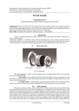
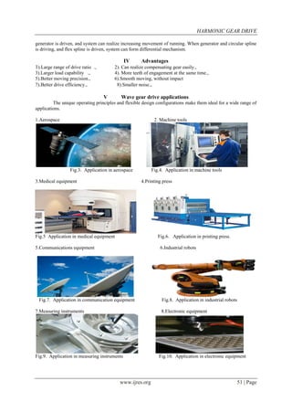
This document summarizes the key components and operating principles of a wave gear drive system. It discusses how wave gear drives provide advantages over traditional gearing systems such as zero backlash, high torsional stiffness, and high positional accuracy. The main components of a wave gear drive are the flex spline, wave generator, and circular spline. The wave generator causes deformation of the flex spline to partially engage and disengage its teeth with the circular spline's teeth, allowing for gear reductions. Wave gear drives have applications in aerospace, machine tools, medical equipment, printing presses, robots, and more due to their flexible design and performance advantages.
(MEERA) Dapodi Call Girls Just Call 7001035870 [ Cash on Delivery ] Pune Escorts
Ā
WAVE GEAR
1. International Journal of Research in Engineering and Science (IJRES)
ISSN (Online): 2320-9364, ISSN (Print): 2320-9356
www.ijres.org Volume 2 Issue 5 Ē May. 2014 Ē PP.50-53
www.ijres.org 50 | Page
WAVE GEAR
Vidyadharan P K
(Mechanical,Mahendra college of Engineering/Anna University,India)
ABSTRACT:- Wave gear drives have been widely used in many industrial fields. It is a popular choice for
many automation applications because of its superior power transmission qualities, which include zero backlash,
high torsional stiffness, high positional accuracy, and torque to weight ratios.
Key words:- Flex spline, Wave generator , Positional accuracy , Zero backlash
I. Introduction
A gear is a rotating machine part having cut teeth, or cogs, which mesh with another toothed part in
order to transmit torque.
Automation equipment is constantly seeking increased throughput-it's a never ending requirement. Wave
Gearing (also known as are strain wave gears) is a special type of mechanical gear system that can improve
certain characteristics compared to traditional gearing systems (such as Helical Gears or Planetary Gears)
II Wave gear drive
Fig.1 Components
The wave generator is made up of two separate parts: an elliptical disk called a wave generator
plug and an outer ball bearing.
The flex spline is like a shallow cup. The flex spline fits tightly over the wave generator, so that
when the wave generator plug is rotated, the flex spline deforms to the shape of a rotating ellipse but does not
rotate with the wave generator.
The circular spline is a rigid circular ring with teeth on the inside. The flex spline and wave
generator are placed inside the circular spline, meshing the teeth of the flex spline and the circular spline.
III Drive principle
When wave generator is driving, cam runs inside the flex spline, and make flex spline and shell bearing
occurring deformation, now flex splineās teeth will engaging-in or engaging-out between circular splineās teeth
during the course of deformation, and itās in complete engaging-in at wave generatorās major axis, and teeth at
minor axis in complete disengagement. Wave generator usually is elliptic cam, put the cam in shell bearing, and
then put them into flex spline. Now, flex spline will change from original circle to ellipse, flex spline at two
ends of elliptic major axis and the matched circular spline teeth are at the complete engaging-in state, namely
flex splineās external gear and circular splineās annular gear engaging-in along tooth depth. This is engagement
area, usually about 30% teeth are at engagement state; When circular spline is driving, flex spline and wave
2. HARMONIC GEAR DRIVE
www.ijres.org 51 | Page
generator is driven, and system can realize increasing movement of running. When generator and circular spline
is driving, and flex spline is driven, system can form differential mechanism.
IV Advantages
1).Large range of drive ratio ., 2). Can realize compensating gear easily.,
3).Larger load capability ., 4). More teeth of engagement at the same time.,
5).Better moving precision., 6).Smooth moving, without impact
7).Better drive efficiency., 8).Smaller noise.,
V Wave gear drive applications
The unique operating principles and flexible design configurations make them ideal for a wide range of
applications.
1.Aerospace 2. Machine tools
Fig.3. Application in aerospace Fig.4. Application in machine tools
3.Medical equipment 4.Printing press
Fig.5 Application in medical equipment Fig.6. Application in printing press.
5.Communications equipment 6.Industrial robots
Fig.7. Application in communication equipment Fig.8. Application in industrial robots
7.Measuring instruments 8.Electronic equipment
Fig.9. Application in measuring instruments Fig.10. Application in electronic equipment
3. HARMONIC GEAR DRIVE
www.ijres.org 52 | Page
VI Literature review on harmonic gear drive
1. C.W. Musser The basic concept of strain wave gearing (SWG) was introduced in his 1957 patent.
Authors mainly worked on symmetric teeth harmonic gear drive than asymmetric teeth harmonic gear drive
2.Mananori Kikuchi, et al made a study on stress analysis of cup type strain wave gearing. In the
strain wave gearing, the flexspline is a thin wall cylinder with external teeth, the circular spline is a rigid ring
with internal teeth, and a wave generator is oval bearing.
3.Huming Dong and Delun Wang has studied about elastic deformation characteristic of the
flexspline in harmonic gear drive. By means of double cubic spline function, the deformation function with
discrete data is fitted. The paper lays on groundwork for further kinematics analysis.
VII. Conclusion
It has been also concluded from interference analysis done in workbench .Thus may be the flexspline
cup stresses will be less. It has been found that the teeth engagement is good .The torque results show that it can
carry more torque as compared to normal gear and concluded that the performance of the wave gear will be far
better than the other drive
References
[1] Cavdar K., Karpat F., Babalik F. B., āComputer Aided Analysis of Bending Strength of Involute Spur Gears with Asymmetric
Profileā, Journal of Mechanical Design, Vol. 127 / 477, MAY, 2005.
[2] Maiti R., āA Novel Harmonic Drive with Pure Involute Tooth Gear Pairā, ASME, Vol. 126, January, 2004
[3] Routh B., Maiti R., āOn Gearing Problem in Conventional Harmonic Drives With Involute Toothed Gear Setā, Proceedings of the
ASME 2011 International Design Engineering Technical Conferences and Computers and Information in Engineering Conference,
Washington, DC, USA, August 28-31, 2011.