INTRODUCTION
Strain Wave Gearing(also known as "harmonic drive" because Harmonic Drive
gears are strain wave gears produced by the Harmonic Drive companies) is a special
type of mechanical gear system that can improve certain characteristics compared
to traditional gearing systems (such as Helical Gears or Planetary Gears)
Harmonic Drives (HD) were invented in the late 1950 by C. Walton Musser.
This mechanical transmission employs a continuous deflection wave along non
rigid gear to allow for gardual engagement of gear teeth.Because of this
unconventional gear tooth meshing action ,harmonic drives can deliver high reduction
ratios in a very small package.
The unique performance features of the hamonic drive have captured international
attention from designers as well as researchers.
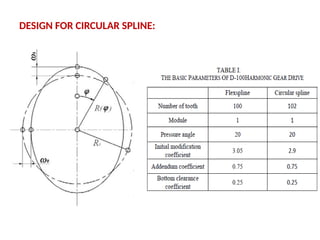
CIRCULAR SPLINE
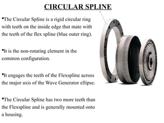
The CircularSpline is a rigid circular ring
with teeth on the inside edge that mate with
the teeth of the flex spline (blue outer ring).
It is the non-rotating element in the
common configuration.
It engages the teeth of the Flexspline across
the major axis of the Wave Generator ellipse.
The Circular Spline has two more teeth than
the Flexspline and is generally mounted onto
a housing.
5.
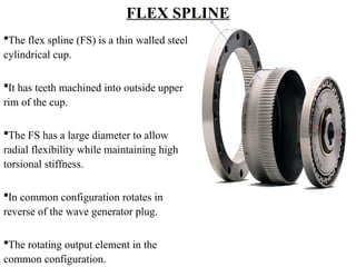
FLEX SPLINE
The flexspline (FS) is a thin walled steel
cylindrical cup.
It has teeth machined into outside upper
rim of the cup.
The FS has a large diameter to allow
radial flexibility while maintaining high
torsional stiffness.
In common configuration rotates in
reverse of the wave generator plug.
The rotating output element in the
common configuration.
6.
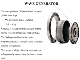
WAVE GENERATOR
The wavegenerator (WG) consists of two parts:
(yellow inner ring)
An elliptically shaped steel plug
Ball bearing
The plug is pressed into the bearing so that the
bearing conforms to the plugs elliptical shape.
The WG is pressed into the flex spline.
The WG is attached to the drive input in the most
common configuration.
This serves as a high efficiency torque converter
and is generally mounted onto the input or motor
shaft.
7.
MATERIALS USED
CIRCULAR SPLINE:
Thedifferent functions(tooth area,interface to mounting structure,etc.)
make corrosion prevention by surface coating very difficult, the use of
stainless steel is preferred.
The use of a thin lubricant film is not sufficient to avoid cold welding
between the Circular Spline and Flexspline, therefore these two parts are
made of different steel types.
8.
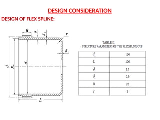
FLEX SPLINE:
The HarmonicDrive Gear is designed so that the Flexspline operates in
its infinite fatigue life region.
This is ensured by using high performance steel or titanium and optimized shaping of the
tooth root and the contour of the cup itself.
The different tribological surfaces (teeth area and the interface to the Wave Generator) pose
additional requirements on the material selection and surface hardness and roughness.
A detailed test and qualification program is required before a new material can be
introduced.
9.
WAVE GENERATOR:
The WaveGenerator bearing is a specially designed thin wall bearing.
Due to the limitations of materials used for bearings and the special
design of the bearing the choice in most cases is 440C.
New materials such as Cronidur are under investigation.
10.
WORKING PRINCIPLE
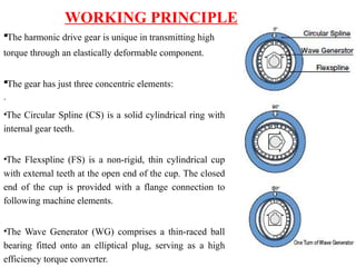
The harmonicdrive gear is unique in transmitting high
torque through an elastically deformable component.
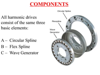
The gear has just three concentric elements:
·
•The Circular Spline (CS) is a solid cylindrical ring with
internal gear teeth.
•The Flexspline (FS) is a non-rigid, thin cylindrical cup
with external teeth at the open end of the cup. The closed
end of the cup is provided with a flange connection to
following machine elements.
•The Wave Generator (WG) comprises a thin-raced ball
bearing fitted onto an elliptical plug, serving as a high
efficiency torque converter.
11.
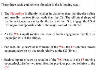
These three basiccomponents function in the following way:-
1. The Flexspline is slightly smaller in diameter than the circular spline
and usually has two fewer teeth than the CS. The elliptical shape of
the Wave Generator causes the the teeth of the FS to engage the CS at
two regions at opposite ends of the major axis of the ellipse.
2. As the WG (input) rotates, the zone of tooth engagemen travels with
the major axis of the ellipse.
3. For each 180 clockwise movement of the WG, the FS (output) moves
counterclockwise by one tooth relative to the CS (fixed).
4. Each complete clockwise rotation of the WG results in the FS moving
counterlockwise by two teeth from its previous position relative to the
CS.
12.
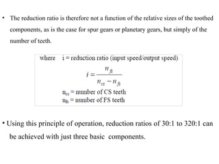
• The reductionratio is therefore not a function of the relative sizes of the toothed
components, as is the case for spur gears or planetary gears, but simply of the
number of teeth.
• Using this principle of operation, reduction ratios of 30:1 to 320:1 can
be achieved with just three basic components.
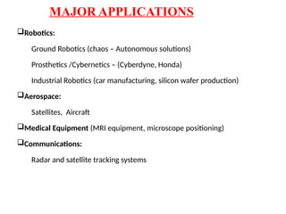
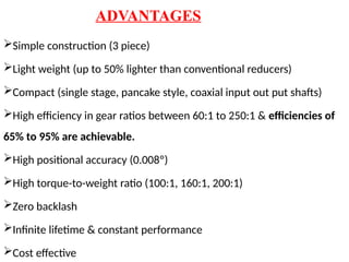
ADVANTAGES
Simple construction (3piece)
Light weight (up to 50% lighter than conventional reducers)
Compact (single stage, pancake style, coaxial input out put shafts)
High efficiency in gear ratios between 60:1 to 250:1 & efficiencies of
65% to 95% are achievable.
High positional accuracy (0.008º)
High torque-to-weight ratio (100:1, 160:1, 200:1)
Zero backlash
Infinite lifetime & constant performance
Cost effective
15.
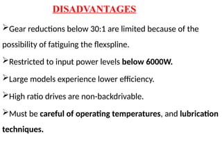
DISADVANTAGES
Gear reductions below30:1 are limited because of the
possibility of fatiguing the flexspline.
Restricted to input power levels below 6000W.
Large models experience lower efficiency.
High ratio drives are non-backdrivable.
Must be careful of operating temperatures, and lubrication
techniques.
LUBRICATION
• For thewave generator bearing, perfluorinated oil e.g.
Fomblin Z25 or Brayco 815Z, is typically used. The
phenolic resin bearing retainer is impregnated with
oil in a vacuum environment.
• The gear teeth are typically lubricated with grease.
20.
COST
•Harmonic Drives rangein cost based on size, lubrication, and
configuration type.
•The drive costs a bit more than other reduction devices, but
the savings is made up by being able to reduce the
requirements for the motor and the savings in size and weight.
21.
CONCLUSION
•Harmonic Drive gearshave a long success story in demanding robotic applications.
•One area of particular interest is the development of lightweight gears. The latest
research results can reduce weight by more than 50 % without any reduction in
torque capacity or accuracy.
•This research is continuing with gears manufactured from titanium using special
surface treatments currently being tested. It is anticipated that this development can
lead to even better performance that that already achieved using composite or
aluminium components.
22.
REFERENCE LIST
H., Dong,K. L.,Ting, and D., Wang, 2011, “Kinematic Fundamentals of Planar harmonic drives”,
ASME J. Mich.Des, 2011.01, pp.0110071-7.
Dynamic Simulation of Harmonic Gear Drives Considering Tooth Profiles Parameters
Optimization,By Huimin Dong, VOL. 7, NO. 6, JUNE 2012,Pg no 1429-1436
School of mechanical engineering, Dalian University of Technology, Dalian 116024, PR China.
K. Löffler, M. Gienger, F. Pfeiffer:
Sensor and Control Design of a Dynamically Stable
Biped Robot
Proc. of 2003 IEEE International Conference on
Robotics and Automation
Schäfer, B. Hirzinger, G.:
On Design, Dynamics and Simulation of Space
Robotics at DLR
Proc. of 2nd International Congress on Mechatronics,
Graz, 2003
Slatter, R.:
Leichtbaugetriebe für Roboter in der Raumfahrt
Antriebstechnik 41 (2002) Nr. 11