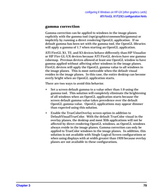
This document provides guidance on configuring the X Windows system on HP-UX systems with various graphics cards, including HP Visualize cards. It describes the X configuration files used, such as X*screens and XF86Config, and covers topics like configuring displays, monitors, input devices and extensions. The document also provides sample configuration files and device-specific information.


![configuring X Windows on HP-UX (HP Visualize graphics cards)
X Server configuration
Chapter 212
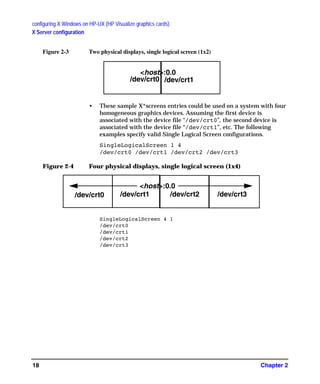
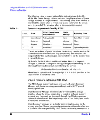
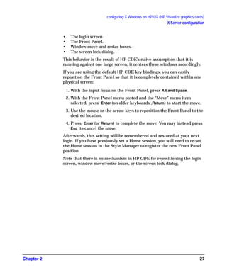
X*screens file
For manual changes, please refer to the sample files in the /etc/X11/ directory.
Three files of particular interest are the X0screens, X0devices, and X0pointerkeys
files.
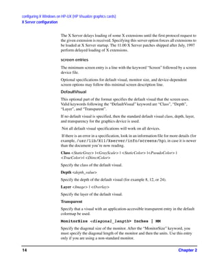
description of the X*screens configuration file
This file belongs in /etc/X11/X*screens, where “*” is the display number of
the server. For example, the “X0screens” file is used when the $DISPLAY
environment variable is set to hostname:0.screen and the server is invoked
using the “:0” option.
The X*screens file is used to specify:
• Device-independent server options, and
• For each screen:
— what device file to use (required),
— the default visual,
— monitor size, and
— device-dependent screen options.
Note that all of the items above, except for device-independent server options, are
specified on a per-screen basis.
The X Server supports up to four screens at a time. Specifying more than four
screens will cause a server error message.
syntax guidelines
• Blank lines and comments (text following “#”) are ignored.
Entries can occupy more than a single line.
• All symbols in the file are recognized case-insensitive.
the X*screens file format
Items must appear in the X*screens file in the order that they are specified below.
[ServerOptions
<server_option>
.
.
.
<server_option>]
{Screen <device_name>} ||
GAG11.book Page 12 Tuesday, February 14, 2006 9:11 AM](https://image.slidesharecdn.com/hpuxxserver-150615121018-lva1-app6891/85/Hp-ux-x_server-14-320.jpg)
![configuring X Windows on HP-UX (HP Visualize graphics cards)
X Server configuration
Chapter 2 13
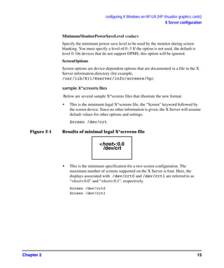
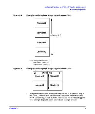
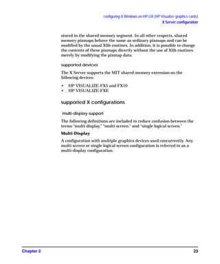
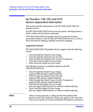
{SingleLogicalScreen <nRows> <nCols>
<device_name1> . . .< device_nameN>}
[DefaultVisual
[Class <visual_class>]
[Depth <depth>]
[Layer <layer>]
[Transparent]]
[MonitorSize <diagonal_length>< units>]
[MinimumMonitorPowerSaveLevel <level>]
[ScreenOptions
<screen_option>
.
.
.
<screen_option>]
Brackets (“[“and “]”) denote optional items. Italicized items in angle brackets (“<”
and “>”) denote values to be specified. The double vertical line (“||”) denotes that
one of the ored values (items surrounded by braces, “{“and “}”) must be included.
The block from the “Screen <device_name>” line to the final “<screen_option>”
line is referred to as a either a “Screen Entry” or as a “Single Logical Screen entry”.
As shown above, the X*screens format is composed of an optional block specifying
device-independent server options followed by one or more either Screen or Single
Logical Screen entries (maximum of four graphics devices).
The minimum X*screens file is a line with the keyword “Screen” followed by a
screen device file. For example:
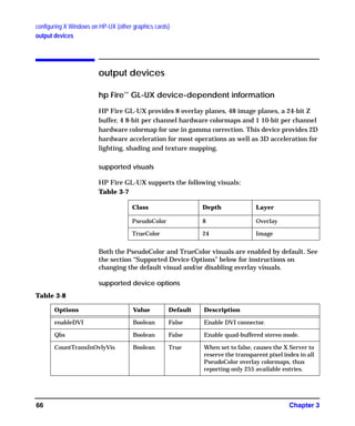
Screen /dev/crt
server options
For more information about server options, or about additional server options, look
in an information file (for example,
/usr/lib/X11/Xserver/info/screens/hp).
GraphicsSharedMemorySize <memory_size>
Specify the size of the graphics shared memory region. The size must be specified in
bytes and must be in hexadecimal.
Default value: 0x580000
ImmediateLoadDles
GAG11.book Page 13 Tuesday, February 14, 2006 9:11 AM](https://image.slidesharecdn.com/hpuxxserver-150615121018-lva1-app6891/85/Hp-ux-x_server-15-320.jpg)
![configuring X Windows on HP-UX (HP Visualize graphics cards)
X Server configuration
Chapter 2 25
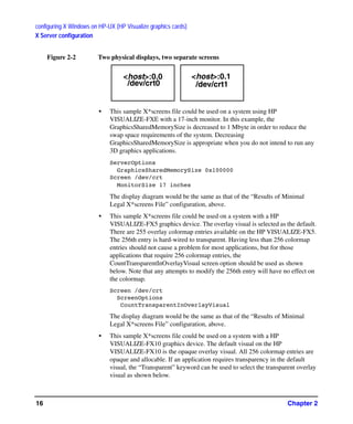
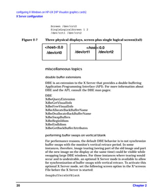
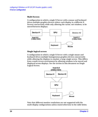
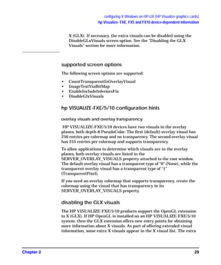
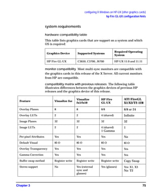
multi-screen support
The list of supported multi-display configurations is rather large, and it
changes whenever a new graphics device is introduced. Thus, if you are
considering a Single Logical Screen or any other multi-display
configuration, we recommend consulting your HP Sales Representative
and inquiring whether the configuration you have in mind is indeed
supported.
There are general guidelines, however. For example:
• Multi-display configurations may be limited by available power.
Depending on the capacity of your computer’s power supply, and the
power demands of the combination of graphics cards you are
considering, there may or may not be enough power to operate them
all.
• Single Logical Screen configurations must use identical graphics
devices (see the next section).
single logical screen (SLS)
SLS is a mechanism for treating homogeneous multi-display
configurations as a single “logical” screen. This allows the
moving/spanning of windows across multiple physical monitors. The
word “homogeneous” is included because SLS only works if the graphics
devices included in the SLS Configuration are of the same type.
SLS is enabled by using SAM (the System Administration Manager tool,
/usr/sbin/sam). To enable an SLS configuration, start SAM, and
follow the instructions below:
1. Double-click on the “X Server Configuration” button. A window
entitled “Graphics” appears, containing an icon for every graphics device
on your system.
2. Select the devices you want to combine into an SLS (click the mouse on
the first device, and [Ctrl]-click on the others). At this point, all the
devices you want to combine into an SLS configuration should be
highlighted.
3.From the “Actions” menu, choose the menu item “Modify Multi-Screen
Layout”. A dialog box appears, allowing you to specify exactly how you
want your SLS configuration to be.
GAG11.book Page 25 Tuesday, February 14, 2006 9:11 AM](https://image.slidesharecdn.com/hpuxxserver-150615121018-lva1-app6891/85/Hp-ux-x_server-27-320.jpg)
![configuring X Windows on HP-UX (other graphics cards)
using SAM to configure X Windows
Chapter 334
other graphics cards. Running independent X Servers on an HP
Visualize graphics device and any other device simultaneously is not
supported.
SLS is a mechanism for treating homogeneous multi-display
configurations as a single logical screen. This allows the
moving/spanning of windows across multiple physical monitors. The
word homogeneous is included because SLS only works if the graphics
devices included in the SLS Configuration are of the same type.
To enable an SLS configuration, start SAM, select the "Display" icon, and
follow the instructions below:
1. Double-click on the "X Server Configuration" button. A window
entitled "X Server Configuration" appears, containing an icon for every
graphics device on your system.
2. Select the devices you want to combine into an SLS configuration. To
select the devices, click the mouse on the first device, and [Ctrl]-click on
the others. At this point, all the devices you want to combine into an SLS
configuration should be highlighted.
3. From the "Actions" menu, choose the it "Single Logical Screen (SLS)"
-> "Create SLS..."
4. In the "Create SLS" screen, select the desired layout (horizontal or
vertical) and screen mapping, and click "OK".
5. The "X Server Configuration" window should now show a single icon
denoting an SLS confguration.
6. Select "File -> Exit". This will save the new SLS configuration and
give you the option to restart the Xserver. The Xserver will need to be
restarted for the new SLS configuration settings to take effect.
Specific Xf86 server options can be set with the Modify Server Options
menu item. See the item for information on specific options.
The second group of “Actions” menus can be thought of as screen actions.
They will be activated depending on which screens have been chosen.
The windows that result from choosing on of these actions differ
depending upon whether the selected screen is an HP Visualize graphics
card or other HP graphics cards.
The Describe Screen and Identify Screen menu selections provide
information about the device. Identify Screen flashes the monitor that
is connected to the graphics device.
GAG11.book Page 34 Tuesday, February 14, 2006 9:11 AM](https://image.slidesharecdn.com/hpuxxserver-150615121018-lva1-app6891/85/Hp-ux-x_server-36-320.jpg)
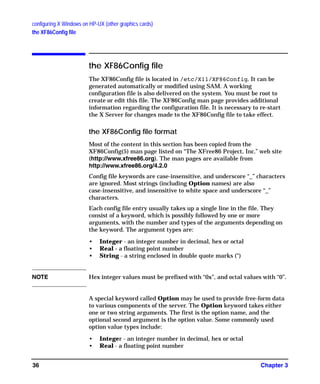
![configuring X Windows on HP-UX (other graphics cards)
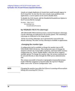
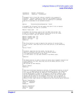
the XF86Config file
Chapter 338
Section ìServerLayoutî
Identifier ìServerLayoutNameî
Screen [ScreenNumber] ìScreenIDî [Position] [Xcoor] [Ycoor]
. . .
InputDevice ìInputDeviceIDî ìInputDeviceOptionî
. . .
[Option Ö]
. . .
EndSection
Keywords, options and values enclosed in [ ] are optional.
A number specifying the preferred screen number for that screen may
optionally follow each Screen. When no screen number is specified, it is
numbered according to the order in which it is listed. Next comes the
ScreenID, a required field that must be enclosed in double quotes. The
ScreenID must match an Identifier in a Screen section. The
remaining information on the line is optional. Next comes the physical
position of the screen, either in absolute terms or relative to another
screen (or screens). Finally the XY coordinates of the screen may be
specified.
The position keywords are:
Absolute
RightOf
LeftOf
Above
Below
Relative
The preferred method of specifying the layout is to explicitly specify the
screen's location in absolute terms or relative to another screen.
The examples are based on the examples listed in the DESIGN document
from XFree86.
In the absolute case, the upper left corner's coordinates are given after
the Absolute keyword. If the coordinates are omitted, a value of (0,0) is
assumed. An example of absolute positioning follows:
GAG11.book Page 38 Tuesday, February 14, 2006 9:11 AM](https://image.slidesharecdn.com/hpuxxserver-150615121018-lva1-app6891/85/Hp-ux-x_server-40-320.jpg)
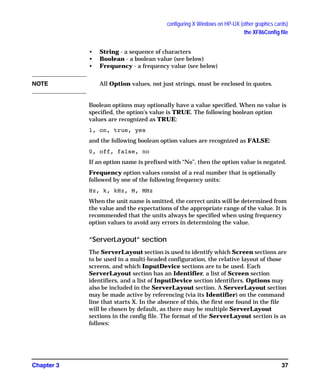
![configuring X Windows on HP-UX (other graphics cards)
the XF86Config file
Chapter 3 41
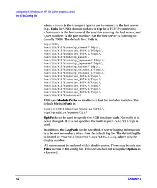
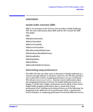
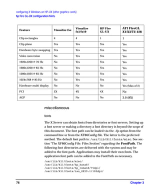
“Files” section
The Files section is used to specify paths to where fonts and modules are
located and the location of the rgb database and the user specified logfile.
The Files section format is:
ìFilesî Section
[FontPath ìPathNameî]
.
.
[ModulePath ìPathNameî]
.
.
[RgbPath ìPathNameî]
[LogPath ìPathNameî]
Endsection
Multiple Font Paths and Module Paths may be specified in two ways,
either by multiple lines or by using a “,” delimiter between paths on the
same line.
Font Path elements may be either absolute directory paths, or a font
server identifier. Font server identifiers have the form:
<trans>/<hostname>:<port-number>
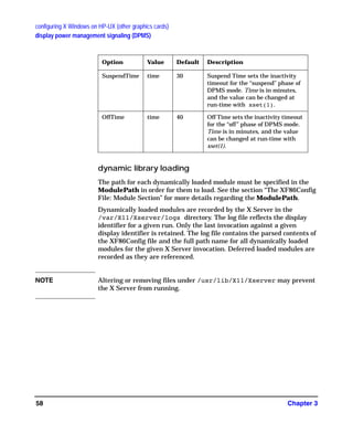
CursorScaleFactor Integer 1 See the section in “Features: ” for more
details regarding these options.
MaxCursorSize Integer 64 See the section in “Features: Cursor
Scaling” for more details regarding
these options.
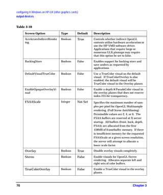
AcelerateIndirectRendering Boolean True This option is used to specify whether
or not OpenGL is to do software
rendering. A value of False forces
software rendering. The default is for
OpenGL to use accelerated rendering.
Table 3-1 (Continued)
GAG11.book Page 41 Tuesday, February 14, 2006 9:11 AM](https://image.slidesharecdn.com/hpuxxserver-150615121018-lva1-app6891/85/Hp-ux-x_server-43-320.jpg)
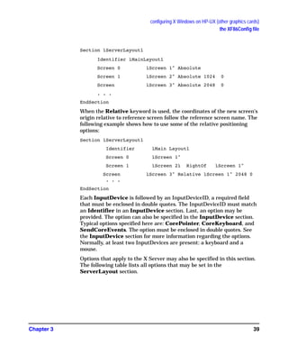
![configuring X Windows on HP-UX (other graphics cards)
the XF86Config file
Chapter 3 43
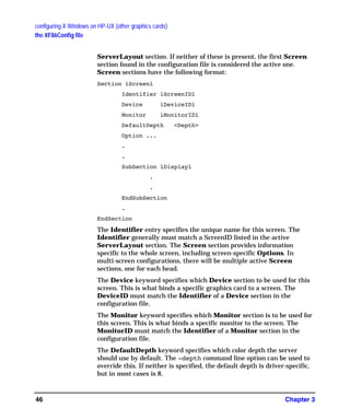
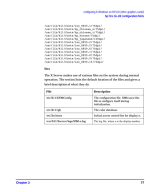
“Module” section
The Module section is used to specify which X Server modules should be
loaded. The types of modules normally loaded in this section are X Server
extension modules, and font rasterizer modules. Most other module types
are loaded automatically when they are needed via other mechanisms.
There may only be one Module section in the config file. The format of
the Module section is as follows:
Section ìModuleî
Load ìModuleNameî
. . .
[SubSection ìModuleNameî
Option . . .
. . .
EndSubSection]
. . .
EndSection.
Load instructs the server to load the module called ModuleName. The
module name given should be the module's extension name, not the
module file name. The extension name is case-sensitive, and does not
include the “lib” prefix, or the “.1” suffix.
Example: the Double Buffered Extension (DBE) can be loaded with the
following entry:
Load ìdbeî
SubSection also instructs the server to load the module called
ModuleName. The module name given should be the module's
extension name, not the module file name. The extension name is
case-sensitive, and does not include the “lib” prefix, or the “.1” suffix. The
difference is that the listed Options are passed to the module when it is
loaded.
Modules are searched for in each directory specified in the ModulePath
search path (or the default ModulePath if one is not specified in the
Files section) and in the drivers, input, extensions, fonts, and HP-UX
subdirectories of each directory in the ModulePath.
GAG11.book Page 43 Tuesday, February 14, 2006 9:11 AM](https://image.slidesharecdn.com/hpuxxserver-150615121018-lva1-app6891/85/Hp-ux-x_server-45-320.jpg)
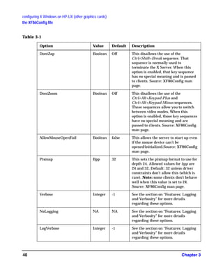
![configuring X Windows on HP-UX (other graphics cards)
the XF86Config file
Chapter 344
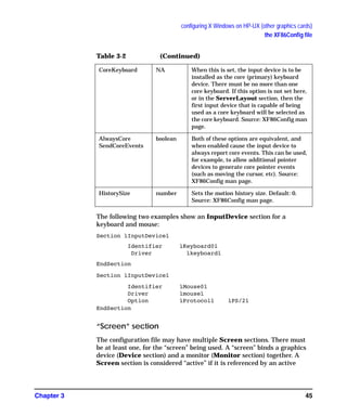
“InputDevice” section
An InputDevice section is considered active if there is a reference to it
in the active ServerLayout section. There may be multiple
InputDevice sections. There will normally be at least two: one for the
core (primary) keyboard, and one for the core pointer. InputDevice
sections have the following format:
Section ìInputDeviceî
Identifier ìInputDeviceIDî
Driver ìDriverNameî
[Option Ö]
. . .
EndSection
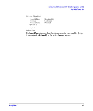
The Identifier entry specifies the unique name for this input device and
must match an InputDeviceID in the active ServerLayout section in
order to be active.
The Driver entry specifies the name of the driver to use for this input
device.
InputDevice sections recognize some driver-independent Options,
which are described here. See the individual input driver manual pages
for a description of the device-specific options that can be entered here.
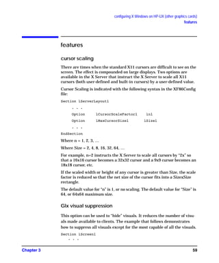
Table 3-2
Option Value Description
CorePointer NA When this is set, the input device is
installed as the core (primary) pointer
device. There must be no more than one
core pointer. If this option is not set here, or
in the ServerLayout section, or from the
-pointer command line option, then the first
input device that is capable of being used as
a core pointer will be selected as the core
pointer. Source: XF86Config man page.
GAG11.book Page 44 Tuesday, February 14, 2006 9:11 AM](https://image.slidesharecdn.com/hpuxxserver-150615121018-lva1-app6891/85/Hp-ux-x_server-46-320.jpg)
![configuring X Windows on HP-UX (other graphics cards)
the XF86Config file
Chapter 3 49
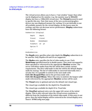
Option flags may be specified in the Display subsections. These may
include driver-specific options or driver-independent options. The former
are described in the driver-specific documentation. Some of the latter are
described above in the section about the Screen section, and they may
also be included here. However, options set in the Display subsection
may be “overridden” in the Screen section.
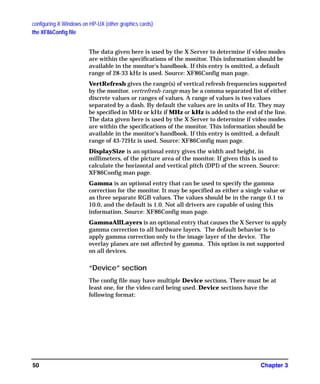
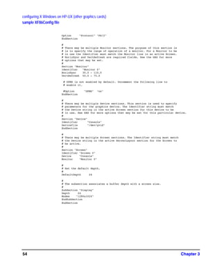
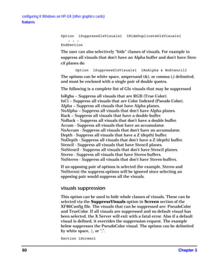
“Monitor” section
The configuration file may have multiple Monitor sections. The
Monitor section provides information about the specifications of the
monitor, monitor-specific Options, and information about the video
modes to use with the monitor. There must be at least one Monitor
section, for the monitor being used. A Monitor section is considered
“active” if it is referenced by an active Screen section. Monitor sections
have the following format:
Section ìMonitorî
Identifier ìMonitorIDî
VendorName ìVnameî
ModelName ìMnameî
HorizSync horizsync-range
VertRefresh vertrefresh-range
DisplaySize width height
Gamma [gamma-value|{red-gamma green-gamma blue-gamma}]
GammaAllLayers [on | true | 1]
EndSection
The Identifier entry specifies the unique name for this monitor.
The VendorName is an optional entry and is used to specify the
monitor's manufacturer.
This ModelName is an optional entry that is used to specify the monitor
model.
HorizSync gives the range(s) of horizontal sync frequencies supported
by the monitor. horizsync-range may be a comma separated list of either
discrete values or ranges of values. A range of values is two values
separated by a dash. By default the values are in units of kHz. They may
be specified in MHz or Hz if MHz or Hz is added to the end of the line.
GAG11.book Page 49 Tuesday, February 14, 2006 9:11 AM](https://image.slidesharecdn.com/hpuxxserver-150615121018-lva1-app6891/85/Hp-ux-x_server-51-320.jpg)


![X Windows configuration details
making an x*.hosts file
Chapter 4 81
• The user must have a valid login (username and password) and home
directory on the remote host.
stopping the X Window system
After stopping all application programs, stop the window system by
holding down the Ctrl and Shift keys, and then pressing the Pause/Break
key. This stops the display server, and with it the window system.
customizing the mouse and keyboard
This section describes various customizations that can modify the
default keyboard and mouse behavior.
changing mouse button actions
The xmodmap utility can be used to change mouse button mappings. The
syntax for changing mouse button mappings with xmodmap is:
xmodmap {-e ìpointer = {default | number [number...]}î | -pp}
where:
-e
Specifies a remapping expression. Valid expressions are covered in
“Customizing Keyboard Input”.
default
Set mouse keys back to default bindings.
number
Specifies a list of button numbers to map the mouse keys to. The order of
the numbers refers to the original button mapping.
pp
Print the current pointer mapping.
For example, to reverse the positions of buttons 1 and 3 for left-handed
mapping:
xmodmap -e “pointer = 3 2 1" (2-button mouse)
xmodmap -e “pointer = 3 2 1 5 4" (3-button mouse)
To establish OSF/Motif-standard button mapping:
xmodmap -e “pointer = 1 3 2" 2-button mouse
GAG11.book Page 81 Tuesday, February 14, 2006 9:11 AM](https://image.slidesharecdn.com/hpuxxserver-150615121018-lva1-app6891/85/Hp-ux-x_server-84-320.jpg)
![X Windows configuration details
making an x*.hosts file
Chapter 482
xmodmap -e “pointer = 1 3 2 4 5" 3-button mouse
modifying modifier key bindings with xmodmap
To change the meaning of a particular key for a particular X11 session,
or to initialize the X Server with a completely different set of key
mappings, use the xmodmap client.
The syntax for xmodmap is as follows: xmodmap <options> [<filename>]
where <options> are:
-display <host>:<display>
Specifies the host, display number, and screen to use.
-help
Displays a brief description of xmodmap options.
-grammar
Displays a brief description of the syntax for modification expressions.
-verbose
Prints log information as xmodmap executes.
-quiet
Turns off verbose logging. This is the default.
-n
Lists changes to key mappings without actually making those changes.
-e <expression>
Specifies a remapping expression to be executed.
-pm, -p
Prints the current modifier map to the standard output. This is the
default.
-pk
Prints the current keymap table to the standard output.
-pp
Print the current pointer map to the standard output.
- (dash)
Specifies that the standard input should be used for the input file.
<filename>
Specifies a particular key mapping file to be used.
GAG11.book Page 82 Tuesday, February 14, 2006 9:11 AM](https://image.slidesharecdn.com/hpuxxserver-150615121018-lva1-app6891/85/Hp-ux-x_server-85-320.jpg)
![X Windows configuration details
making an x*.hosts file
Chapter 484
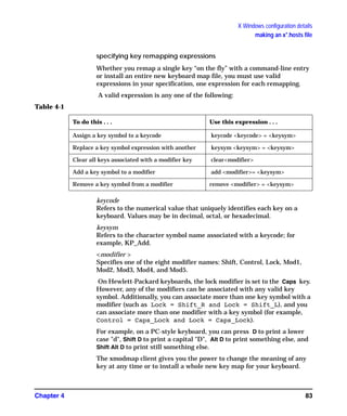
examples
Suppose you frequently press the Caps key at the most inopportune
moments. You could remove the Caps lock key from the lock modifier,
swap it for the f1 key, then map the f1 key to the lock modifier. Do this by
creating a little swapper file that contains the following lines:
!This file swaps the [Caps] key with the [F1] key.
remove Lock = Caps_Lock
keysym Caps_Lock = F1
keysym F1 = Caps_Lock
add Lock = Caps_Lock
Note the use of the ! in the file to start a comment line. To put your
"swapper" file into effect, enter the following on the command line:
xmodmap swapper
If you use such a swapper file, you should probably have an unswapper
file. The following file enables you to swap back to the original keyboard
mapping without having to exit X11:
!This file unswaps the [F1] key with the [Caps] key.
remove Lock = Caps_Lock
keycode 88 = F1
keycode 55 = Caps_Lock
add Lock = Caps_Lock
Note the use of the hexadecimal values to reinitialize the keycodes to the
proper key symbols. You put your “unswapper” file into effect by entering
the following command line:
xmodmap unswapper
On a larger scale, you can change your current keyboard to a Dvorak
keyboard by creating a file with the appropriate keyboard mappings.
xmodmap .keymap
printing a key map
The -pk option prints a list of the key mappings for the current keyboard.
xmodmap -pk
The list contains the keycode and up to four 2-part columns. The first
column contains unmodified key values, the second column contains
shifted key values, the third column contains meta (Extend Char/Alt) key
GAG11.book Page 84 Tuesday, February 14, 2006 9:11 AM](https://image.slidesharecdn.com/hpuxxserver-150615121018-lva1-app6891/85/Hp-ux-x_server-87-320.jpg)


![Cimco edit 5 user guide[1]](https://cdn.slidesharecdn.com/ss_thumbnails/cimcoedit5userguide1-110305112440-phpapp01-thumbnail.jpg?width=640&height=640&fit=bounds)