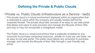
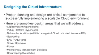
Interested in learning more about Cloud?

       Look at the Cloud sessions offered at the upcoming Fall 2012 Data Center World Conference at:

       www.datacenterworld.com.


This presentation was given during the Spring, 2012 Data Center World Conference and Expo. Contents contained are owned by
AFCOM and Data Center World and can only be reused with the express permission of ACOM. Questions or for permission contact:
jater@afcom.com.
How to Design a Scalable
Private Cloud

                Mark Sand
                Datacenter Architect
                Citrix Systems Inc.
Defining the Private & Public Clouds

• Private vs. Public Clouds (Infrastructure as a Service - IaaS)
 • The private cloud is a virtual environment deployed within an organization that
   is restricted to users within the company and usually resides behind the
   corporate firewall. The private cloud also consists of an easy to use web portal
   that allows end users to auto provision and manage the lifecycle of their VMs,
   and may or may not incorporate a chargeback model.

 • The Public cloud is a virtual environment that is publically available for any
   consumer to purchase computing resources, usually on a pay per use basis, via
   an easy to use web portal. The public cloud allows any consumer to purchase,
   manage, and monitor the lifecycle of their VMs through a user friendly web
   portal.
Designing the Cloud Infrastructure

• Proper planning and design are critical components to
  successfully implementing a scalable Cloud environment
• Here are some key design areas that we will address:
 • Capacity planning and sizing
 • Virtual Platform (hypervisor)
 • Datacenter locations (will this be a global Cloud or hosted from one DC)
 • Networking
 • SAN (NAS/Fibre)
 • Server Hardware
 • Power
 • Monitoring & Management Solutions
 • Documenting the solution
Capacity Planning and Sizing the Environment

• Accurate capacity planning and sizing will ensure that you
  implement a scalable, supportable, and successful
  environment
• Key sizing criteria:
 • Number of VMs you are looking to host per virtual server
 • Number and types of clusters/pools
 • Estimated yearly growth for VMs
 • Amount of storage required to host all of the VMs for current and future growth
 • Amount of estimated network bandwidth required to host the VMs for current
   and future growth
Current Capacity and Sizing Example

• Cluster/pool(s) configuration:
 • We support a mix of 2,4,8, and 16GB VMs in each of our cluster/pool(s)
 • We average approximately 20 VMs per host

             Cluster/Pool   Number of Hosts   Total Storage
           Production             20             20TBs
           QA                     8              9.5TBs
           Dev                    11             15TBs
           DMZ                    6               4TBs
           DR                     15              4TBs
Current Capacity and Sizing cont.

• Average Yearly Growth Statistics:
• VMs account for approximately 85% of our yearly server growth
• We add approximately 5 -10 TBs of storage (spread across all cluster/pool(s))
• We have not needed to add any additional network bandwidth since the
  environment was implemented
Virtual Platform & Datacenter Locations

• Selecting the proper virtual platform (hypervisor):
 • There are several hypervisors out there that have benefits and drawbacks so
   each organization should choose whichever option best fits their needs

• Datacenter Locations:
 • Determine if the cloud will be hosted from several global datacenters or if it will
   be hosted from one central datacenter
 • If the cloud will be hosted from different locations then it is also important to
   follow a set of standards for each of the areas we will be talking about (network,
   storage, server HW, etc.)
Datacenter Locations Example

• US Private Cloud
 • We currently have a large private cloud environment that is hosted out of our
   corporate datacenter as well as a smaller private cloud that is hosted in two
   additional datacenters in the US

• Global Private Cloud
 • We currently have a private cloud environment in three of our regional
   datacenters

• Global Standards
 • We have standardized on the same server hardware/configuration
   and networking devices for the global private cloud; however, we
   were required to create two different storage standards
Network Design

• Define the type of uplinks that will be used:
 • 1GB Uplink
 • Multiple 1GB uplinks configured as a port channel
 • 10GB uplink

• Number/type of uplinks for each of the hosts functions:
 • Virtual Server Management Interface
 • VM traffic
 • NFS/iSCSI traffic for environments utilizing NAS

• Utilize redundant uplinks from separate switches
• Evaluate the proper size & number of VLANs required
Network Description Example

• Network Components
 • Management Network
   • 2 x switches with 2 x 1GB uplinks connected to each switch. Each switch is connected to a different
    distribution layer switch to ensure network redundancy
 • VM Traffic
   • 2 x blade switches with 4 x 1GB uplinks configured as a 2GB port channel is connected to each switch.
    We have three dedicated /24 VLANs for new VMs, and we also trunk existing VLANs to the switches in
    order to account for servers that were P2V’ed and are unable to change their IP address
 • Storage Traffic (regional datacenters only)
   • 2 x blade switches with 4 x 1GB uplinks configured as a 2GB port channel is connected to each switch
Network Diagram Example – Corporate DC


       Note: Storage is connected via an HBA to our fibre channel SAN (not depicted here)
Network Diagram Example – Regional DCs


         Note: Storage for the regional servers are connected to our NAS via NFS
SAN/NAS Design
• NAS vs. Fibre arrays:
 • Each technology has benefits and drawbacks, so each organization should
   choose whichever option best fits their needs

• Define a standard LUN size
• Define a standard naming convention when creating
  LUN/volume(s)
• For NAS ensure to configure a dedicated VLAN for VM
  storage traffic
• For fibre channel SANs ensure that you have two
  independent SAN fabrics (A&B) & utilize multipathing
Storage Example – Corporate DC

• Two fully populated blade enclosures connect into our fibre
  channel SAN via 4GB SAN switches
• We standardized on 2TB LUNs (storage repositories / data
  stores) in our corporate DC and 1TB LUNs regionally
Storage Diagram Example – Corporate DC
Server Hardware

                                                                                                       •Scale
Out vs. Scale Up Methodologies
•Scale Out - several host servers are configured with standard to moderate
 virtualization specs (2 x CPUs & 48 to 128GBs of RAM) that make up a pool/cluster
 • Pros: The servers are less expensive so you can usually grow the pool faster, and you will sustain less downtime
   for VMs if a server fails
 • Cons: There are more servers to manage in each pool/cluster
•Scale Up - only a few host servers are configured with large virtualization specs (4 CPUs
 or greater & 128GBs of RAM or greater) that can handle a large number of VMs
 • Pros: You can run a large number of VMs on the host server due to the vast resources each server has available
 • Cons: The servers are costly so you will likely not be able to grow the pool/cluster as fast, and you will potentially
  have a larger outage for VMs if a host fails
Server Hardware Cont.

                                                                  •Minimu
m specs for virtualization (blade or rack mount):
 • 2 x Quad Core CPUs
 • 48GBs of RAM (96GBs or greater is preferred for large environments)
 • Enough 1GB/10GB NICs that will allow you to have two connections to each
   uplink so you can bond the NICs for redundancy
 • HBA for servers that will connect to the SAN via fibre

                                                       •Ensure
you plan for an additional host server to account for failover
(HA) for each cluster/pool
Server Diagram Example – Corporate DC
• Server specs:
   • 2 x Six Core CPUs
   • 96GBs of RAM
   • 6 x NICs (2 x embedded & 1 quad
      port mezzanine card)
   • 1 x dual port HBA mezzanine card

• Interconnect specs:
    • 4 x network switches (1GB)
    • 2 x 4GB San switches
    • 1 x 1GB Ethernet pass-thru
       module (for backups)
Server Diagram Example – Regional DC
• Server specs:
   • 2 x Quad Core CPUs
   • 96GBs of RAM
   • 8 x NICs (2 x embedded, 1 quad
      port & 1 dual port NIC mezzanine
      card)

• Interconnect specs:
    • 6 x network switches (1GB)
Power Design

• It is important to properly size the power circuits the host
  servers will use since they draw more power than standard
  servers
• Ensure that the environment utilizes two load balanced
  circuits or two independent circuits for redundancy
• Ensure each circuit is terminated from a different feeder
• Separate the virtual host servers into at least two different
  racks
Power Diagram Example – Corporate DC
• Each rack contains:
   • 2 x L6-30 208v (A&B) Single Phase Circuits
   • Each A&B circuit is load balanced
   • 4 x 30amp208v single phase PDUs

• The two blade enclosures that house all of the virtual hosts
  are located in two different racks
Monitoring Solution

• The health of the virtual environment is critical so it is key to
  monitor and alert on some of the following areas:
 • Physical hardware - detect if a DIMM, disk, CPU, etc. goes bad
 • VMs – verify they are online and not over utilized/subscribed
 • Virtual Platform – detect failures within the hypervisor
 • Capacity – verify that each host/cluster/pool is not running out of resources
   (storage, RAM,CPUs, etc.) that would prevent provisioning new VMs

• It usually requires a mix of native and 3rd party tools to
  successfully monitor all aspects of a virtual environment
Management Solution

• Centralized VM and host management is extremely
  important; however, all of the major virtualization vendors do
  provide a centralized management solution
• Auto provisioning of VMs
 • This is a key component of the Cloud and is not always adequately addressed
   by the centralized management solution provided by the virtualization vendors
 • This also often requires a combination of custom (internal) developed
   applications and 3rd party products
 • A good provisioning tool will take into account the utilization of a charge back
   model for VMs, as well as, address proper approvals to control the growth of
   VMs
Management Solution cont.

• How to address VM sprawl?
 • Place proper controls/approvals on who and how many VMs a user can request
 • Automatically track the number, hostname, and type of VM a user creates via
   the self/auto provisioning process
 • Monitor the utilization of all VMs, and then either automatically power the
   underutilized VMs down or follow-up with the VM owner

• We have had our own challenges with trying to implement a
  fully automated solution that incorporates all of our needs,
  and this is something that large companies within the IT
  industry have struggled with as well.
Documenting the solution

• During the design and implementation phase of the
  environment it is important to take detailed notes and
  diagram each of the phases
• A good design document will provide a clear and concise
  view of how all aspects of the environment is configured
• When we handoff any environment to our Operations team
  we provide a detailed design doc, a runbook, and then hold
  an official handoff meeting to cover any questions or
  concerns the Operations team may have.
Questions?
Interested in learning more about Cloud?

       Look at the Cloud sessions offered at the upcoming Fall 2012 Data Center World Conference at:

       www.datacenterworld.com.


This presentation was given during the Spring, 2012 Data Center World Conference and Expo. Contents contained are owned by
AFCOM and Data Center World and can only be reused with the express permission of ACOM. Questions or for permission contact:
jater@afcom.com.

How to Design a Scalable Private Cloud

  • 1.
    Interested in learningmore about Cloud? Look at the Cloud sessions offered at the upcoming Fall 2012 Data Center World Conference at: www.datacenterworld.com. This presentation was given during the Spring, 2012 Data Center World Conference and Expo. Contents contained are owned by AFCOM and Data Center World and can only be reused with the express permission of ACOM. Questions or for permission contact: jater@afcom.com.
  • 2.
    How to Designa Scalable Private Cloud Mark Sand Datacenter Architect Citrix Systems Inc.
  • 3.
    Defining the Private& Public Clouds • Private vs. Public Clouds (Infrastructure as a Service - IaaS) • The private cloud is a virtual environment deployed within an organization that is restricted to users within the company and usually resides behind the corporate firewall. The private cloud also consists of an easy to use web portal that allows end users to auto provision and manage the lifecycle of their VMs, and may or may not incorporate a chargeback model. • The Public cloud is a virtual environment that is publically available for any consumer to purchase computing resources, usually on a pay per use basis, via an easy to use web portal. The public cloud allows any consumer to purchase, manage, and monitor the lifecycle of their VMs through a user friendly web portal.
  • 4.
    Designing the CloudInfrastructure • Proper planning and design are critical components to successfully implementing a scalable Cloud environment • Here are some key design areas that we will address: • Capacity planning and sizing • Virtual Platform (hypervisor) • Datacenter locations (will this be a global Cloud or hosted from one DC) • Networking • SAN (NAS/Fibre) • Server Hardware • Power • Monitoring & Management Solutions • Documenting the solution
  • 5.
    Capacity Planning andSizing the Environment • Accurate capacity planning and sizing will ensure that you implement a scalable, supportable, and successful environment • Key sizing criteria: • Number of VMs you are looking to host per virtual server • Number and types of clusters/pools • Estimated yearly growth for VMs • Amount of storage required to host all of the VMs for current and future growth • Amount of estimated network bandwidth required to host the VMs for current and future growth
  • 6.
    Current Capacity andSizing Example • Cluster/pool(s) configuration: • We support a mix of 2,4,8, and 16GB VMs in each of our cluster/pool(s) • We average approximately 20 VMs per host Cluster/Pool Number of Hosts Total Storage Production 20 20TBs QA 8 9.5TBs Dev 11 15TBs DMZ 6 4TBs DR 15 4TBs
  • 7.
    Current Capacity andSizing cont. • Average Yearly Growth Statistics: • VMs account for approximately 85% of our yearly server growth • We add approximately 5 -10 TBs of storage (spread across all cluster/pool(s)) • We have not needed to add any additional network bandwidth since the environment was implemented
  • 8.
    Virtual Platform &Datacenter Locations • Selecting the proper virtual platform (hypervisor): • There are several hypervisors out there that have benefits and drawbacks so each organization should choose whichever option best fits their needs • Datacenter Locations: • Determine if the cloud will be hosted from several global datacenters or if it will be hosted from one central datacenter • If the cloud will be hosted from different locations then it is also important to follow a set of standards for each of the areas we will be talking about (network, storage, server HW, etc.)
  • 9.
    Datacenter Locations Example •US Private Cloud • We currently have a large private cloud environment that is hosted out of our corporate datacenter as well as a smaller private cloud that is hosted in two additional datacenters in the US • Global Private Cloud • We currently have a private cloud environment in three of our regional datacenters • Global Standards • We have standardized on the same server hardware/configuration and networking devices for the global private cloud; however, we were required to create two different storage standards
  • 10.
    Network Design • Definethe type of uplinks that will be used: • 1GB Uplink • Multiple 1GB uplinks configured as a port channel • 10GB uplink • Number/type of uplinks for each of the hosts functions: • Virtual Server Management Interface • VM traffic • NFS/iSCSI traffic for environments utilizing NAS • Utilize redundant uplinks from separate switches • Evaluate the proper size & number of VLANs required
  • 11.
    Network Description Example •Network Components • Management Network • 2 x switches with 2 x 1GB uplinks connected to each switch. Each switch is connected to a different distribution layer switch to ensure network redundancy • VM Traffic • 2 x blade switches with 4 x 1GB uplinks configured as a 2GB port channel is connected to each switch. We have three dedicated /24 VLANs for new VMs, and we also trunk existing VLANs to the switches in order to account for servers that were P2V’ed and are unable to change their IP address • Storage Traffic (regional datacenters only) • 2 x blade switches with 4 x 1GB uplinks configured as a 2GB port channel is connected to each switch
  • 12.
    Network Diagram Example– Corporate DC Note: Storage is connected via an HBA to our fibre channel SAN (not depicted here)
  • 13.
    Network Diagram Example– Regional DCs Note: Storage for the regional servers are connected to our NAS via NFS
  • 14.
    SAN/NAS Design • NASvs. Fibre arrays: • Each technology has benefits and drawbacks, so each organization should choose whichever option best fits their needs • Define a standard LUN size • Define a standard naming convention when creating LUN/volume(s) • For NAS ensure to configure a dedicated VLAN for VM storage traffic • For fibre channel SANs ensure that you have two independent SAN fabrics (A&B) & utilize multipathing
  • 15.
    Storage Example –Corporate DC • Two fully populated blade enclosures connect into our fibre channel SAN via 4GB SAN switches • We standardized on 2TB LUNs (storage repositories / data stores) in our corporate DC and 1TB LUNs regionally
  • 16.
    Storage Diagram Example– Corporate DC
  • 17.
    Server Hardware •Scale Out vs. Scale Up Methodologies •Scale Out - several host servers are configured with standard to moderate virtualization specs (2 x CPUs & 48 to 128GBs of RAM) that make up a pool/cluster • Pros: The servers are less expensive so you can usually grow the pool faster, and you will sustain less downtime for VMs if a server fails • Cons: There are more servers to manage in each pool/cluster •Scale Up - only a few host servers are configured with large virtualization specs (4 CPUs or greater & 128GBs of RAM or greater) that can handle a large number of VMs • Pros: You can run a large number of VMs on the host server due to the vast resources each server has available • Cons: The servers are costly so you will likely not be able to grow the pool/cluster as fast, and you will potentially have a larger outage for VMs if a host fails
  • 18.
    Server Hardware Cont. •Minimu m specs for virtualization (blade or rack mount): • 2 x Quad Core CPUs • 48GBs of RAM (96GBs or greater is preferred for large environments) • Enough 1GB/10GB NICs that will allow you to have two connections to each uplink so you can bond the NICs for redundancy • HBA for servers that will connect to the SAN via fibre •Ensure you plan for an additional host server to account for failover (HA) for each cluster/pool
  • 19.
    Server Diagram Example– Corporate DC • Server specs: • 2 x Six Core CPUs • 96GBs of RAM • 6 x NICs (2 x embedded & 1 quad port mezzanine card) • 1 x dual port HBA mezzanine card • Interconnect specs: • 4 x network switches (1GB) • 2 x 4GB San switches • 1 x 1GB Ethernet pass-thru module (for backups)
  • 20.
    Server Diagram Example– Regional DC • Server specs: • 2 x Quad Core CPUs • 96GBs of RAM • 8 x NICs (2 x embedded, 1 quad port & 1 dual port NIC mezzanine card) • Interconnect specs: • 6 x network switches (1GB)
  • 21.
    Power Design • Itis important to properly size the power circuits the host servers will use since they draw more power than standard servers • Ensure that the environment utilizes two load balanced circuits or two independent circuits for redundancy • Ensure each circuit is terminated from a different feeder • Separate the virtual host servers into at least two different racks
  • 22.
    Power Diagram Example– Corporate DC • Each rack contains: • 2 x L6-30 208v (A&B) Single Phase Circuits • Each A&B circuit is load balanced • 4 x 30amp208v single phase PDUs • The two blade enclosures that house all of the virtual hosts are located in two different racks
  • 23.
    Monitoring Solution • Thehealth of the virtual environment is critical so it is key to monitor and alert on some of the following areas: • Physical hardware - detect if a DIMM, disk, CPU, etc. goes bad • VMs – verify they are online and not over utilized/subscribed • Virtual Platform – detect failures within the hypervisor • Capacity – verify that each host/cluster/pool is not running out of resources (storage, RAM,CPUs, etc.) that would prevent provisioning new VMs • It usually requires a mix of native and 3rd party tools to successfully monitor all aspects of a virtual environment
  • 24.
    Management Solution • CentralizedVM and host management is extremely important; however, all of the major virtualization vendors do provide a centralized management solution • Auto provisioning of VMs • This is a key component of the Cloud and is not always adequately addressed by the centralized management solution provided by the virtualization vendors • This also often requires a combination of custom (internal) developed applications and 3rd party products • A good provisioning tool will take into account the utilization of a charge back model for VMs, as well as, address proper approvals to control the growth of VMs
  • 25.
    Management Solution cont. •How to address VM sprawl? • Place proper controls/approvals on who and how many VMs a user can request • Automatically track the number, hostname, and type of VM a user creates via the self/auto provisioning process • Monitor the utilization of all VMs, and then either automatically power the underutilized VMs down or follow-up with the VM owner • We have had our own challenges with trying to implement a fully automated solution that incorporates all of our needs, and this is something that large companies within the IT industry have struggled with as well.
  • 26.
    Documenting the solution •During the design and implementation phase of the environment it is important to take detailed notes and diagram each of the phases • A good design document will provide a clear and concise view of how all aspects of the environment is configured • When we handoff any environment to our Operations team we provide a detailed design doc, a runbook, and then hold an official handoff meeting to cover any questions or concerns the Operations team may have.
  • 27.
  • 28.
    Interested in learningmore about Cloud? Look at the Cloud sessions offered at the upcoming Fall 2012 Data Center World Conference at: www.datacenterworld.com. This presentation was given during the Spring, 2012 Data Center World Conference and Expo. Contents contained are owned by AFCOM and Data Center World and can only be reused with the express permission of ACOM. Questions or for permission contact: jater@afcom.com.