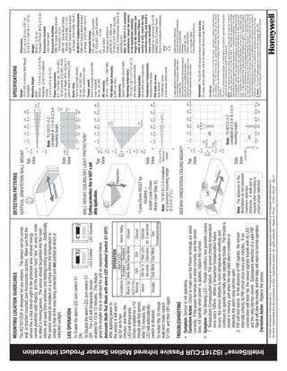
❶     Select the mounting location.                            ❷ Separate the sensor housings and remove the                        ❸    Mount the unit.
                                                                                      Wall Mount
                                                                                                                                                        printed circuit board (PCB).                                             Wiring Knockouts
                                                                                    Ceiling/Sky Light                          Vertical
                                                                                       Protection     Ceiling Mount           Wall Mount
                                                                                                                                                                                    • Use a small screwdriver to
                                                                                                                                                                                      remove the cover screw (if                                                                                Strain
                                                                                                                                                                                      installed), then push in the      Corner                             Corner                               Relief
                                                                                        2.4 m to                                                                                                                        Mount                                                                   Options
                                                                                         3.6 m                                                                                        housing latch at the bottom                                          Mount
                                                                                       (8' to 12’)
                                                                                                                                                                                      of the sensor, and gently pull
                                                                                                     2.3 m (7.5’) 1.5 m to 2.7 m                                                      apart the housings.
                                                                                                      Minimum        (5’ to 9’)


                                                                                                                                                                                                                                                         Wall Mount

                                                                                                                                                                                                                                     Wire Channel


                                                                                    Mounting Location Guidelines
                                                                                    • Mounting Height: Walls: vertical position -- 1.5 m                                                                                • Slide the wire through the wire               [Note: if using a mounting
                                                                                      to 2.7 m (5' to 9'); horizontal position -- 2.3 m                                                                                   knockouts in the back housing, attach         bracket (see Accessories),
                                                                                      (7.5’) minimum.                                                                                                                     the wire with a wire tie, and cut off         follow the installation
                                                                                                                                                   • Push outward on
                                                                                      Ceiling: 2.4 m to 3.6 m (8' to 12').                                                                                                the excess wire tie.                          instructions supplied with
                                                                                                                                                     the PCB latch and
                                                                                    • Avoid direct or reflected sunlight.                                                                                               • Mount the back housing flat against a         the bracket.]
                                                                                                                                                     lift the PCB out of
                                                                                    • Aim sensor away from windows or heating/cooling                                                                                     wall or in a corner using #6 screws.        • Replace the PCB.
                                                                                                                                                     the housing.
                                                                                      devices.
                                                                                    • Sensor must have a clear line-of-sight to protected
                                                                                      area.

                                                                                    ❹     Wire the unit. Connect wires as shown                    ❺ Set the DIP switch settings (see Step 6).                          ❻ Configure the sensitivity and walk-test the sensor.
                                                                                          using wire size 0.8 - 1.5 mm (22 to 16                                                                                             Set the sensitivity appropriate for the application (see options below),
                                                                                          AWG). Observe proper polarity.                                                                       Alarm LED                     replace the front cover, and apply power to the sensor. Begin walk-test
                                                                                                                                                          LED Enable/
                                                                                                                                                                                                                             after the LED stops flashing (see LED Operation section). Walk through
                                                                                                                                                          Disable (S1)
                                                                                                                                                                                                                             the detection zones, observing the sensor’s LED whenever motion is
                                                                                                                                                        Sensitivity (S2)
                                                                                                                                                                                                                             detected. The red LED shows actual alarm relay operation.
                                                                                                                                   POWER                                                                                     The absolute range of all PIR units is subject to variation because of
                                                                                                                                   16 mA, 12 VDC                                                                             different types of clothing, backgrounds, and ambient temperature.
                                                                                                                                   18 mA max
                                                                                                                                                          Install the                                                        For this reason, ensure that the most likely intruder routes are well
                                                                                                                                                     Look-Down Mask                                                          within the PIR’s detection zones and that walk-testing is carried out
                                                                                                                                   ALARM           (black ring supplied)
                                                                                                                                                                                                                             along those routes.
                                                                                                                                   24 VDC          as shown, if desired.
                                                                                                                                   30 mA               Mask MUST be
                                                                                                                                                      installed for wall                                                                                            High Sensitivity (Pulse Count 1)
                                                                                                                                                     mount ceiling/sky                                                                                              NOTE: This is the recommended
                                                                                                                                    TAMPER          light protection and                                                                                            setting for this sensor.
                                                                                                                                    24 VDC              ceiling mount
                                                                                                                                    30 mA               installations.


                                                                                                                                                     SWITCH                    OFF                         ON
                                                                                                                                                       1*                   LED Disabled              LED Enabled                                                   Low Sensitivity (Pulse Count 2)
                                                                                                                                                        2                  Low Sensitivity           High Sensitivity
                                                                                                                                                                                                                                                                    NOTE: If Pulse Count 2 is used,
                                                                                                                                                             (Note: Default switch settings shown in grey.)


IntelliSense® IS216T-CUR Passive Infrared Motion Sensor Installation Instructions
                                                                                                                                                                                                                                                                    be sure to thoroughly walk-test
                                                                                                                                                             *Refer to LED Operation Section.
                                                                                                                                                                                                                                                                    the sensor.
MOUNTING LOCATION GUIDELINES                                                               DETECTION PATTERNS                                                                SPECIFICATIONS
                                                                              The IS216T-CUR is designed for use indoors. The sensor can be corner,                      VERTICAL ORIENTATION WALL MOUNT                                                   Range:                                              Dimensions:
                                                                                                                                                                                                                                                           10 m (33') in Vertical Wall Mount                   8.57 cm x 6.03 cm x 3.81 cm
                                                                              wall, or bracket mounted (see Accessories section). Make sure that the                                                                                                       Orientation                                         (3-3/8" H x 2-3/8" W x 1-1/2" D)
                                                                                                                                                                                                             Top
                                                                              sensor has a clear line-of-sight to the protected area: infrared energy                                                                                                      Mounting Height:                                    Weight:
                                                                                                                                                                                                             View
                                                                              cannot penetrate solid objects, and the sensor must “see” an area in order                                                                                                   Walls:                                              66.62 g (2.35 oz)
                                                                              to detect a moving person. The sensor should be pointed into the room                                                                                                        Vertical - 1.5 m to 2.7 m (5' to 9');               Packaged Product: 89.0 g (3.13 oz)
                                                                                                                                                                                                                                                           Horizontal - 2.3 m (7.5’) minimum                   Accessories Included:
                                                                              interior, and away from windows and heating/cooling sources. Additionally,                                                                                                   Ceiling:
                                                                                                                                                                                                                            Note: TS 50131-2-2                                                                 Look-down mask
                                                                              the sensor should be installed on a surface where the temperature is                                                                                                         2.4 m to 3.6 m (8' to 12')
                                                                                                                                                                                                                            compliant at 1.5 m to 2.3 m                                                        Accessories Available:
                                                                              similar to that of the area being protected and not pointed at direct or                                     tion                                                            Power requirements:                                 SMB-10 Swivel Mount Bracket
                                                                                                                                                                                      Detec                                 mounting height.               8.5 - 15.4 VDC (UL: 10-14 VDC);
                                                                              reflected sunlight.                                                                                                                                                                                                                (P/N 0-000-110-01)
                                                                                                                                                                                                                                                           16 mA nominal at 12 VDC, 18 mA                      SMB-10C Swivel Mount Ceiling
                                                                                                                                                                                                             Side                                          max; AC Ripple: 50 to 120 Hz; 3 V                     Bracket (P/N 0-000-111-01)
                                                                              LED OPERATION                                                                                                                  View                                          peak-to-peak at nominal 12 VDC                      SMB-10T Swivel Mount Bracket
                                                                                                                                                                                                                                                           Alarm relay:                                          w/Tamper (P/N 0-000-155-01)
                                                                              To Enable the alarm LED, turn switch S1                                                                                                                                      Form A (normally closed)                            EN 50131-1 Compliant Accessories:
                                                                              ON.                                                                                                                                                                          30 mA, 24 VDC max.,                                 SMB-10T Swivel Mount Bracket
                                                                                                                                                                         WALL MOUNT CEILING/SKY LIGHT PROTECTION*                                          40 Ohms resistance max                              w/Tamper (P/N 0-000-155-01)
                                                                              To Disable the alarm LED, turn switch S1                                                                                                                                     Tamper switch
                                                                                                                                LED Enabled     LED Disabled             Ceiling protection, this is NOT a pet                                                                                                 Approvals/listings:
                                                                              OFF. The LED will temporarily remain                                                                                                                                         Form A (normally closed with                        FCC part 15, Class B verified
                                                                              enabled for 10 to 12 minutes. This feature                                                 alley application.                                                                cover installed)                                    IC, ICES-003, Class B verified
                                                                                                                                                                                                            Top                                            30 mA, 24 VDC                                       CE             C-Tick
                                                                              gives the installer time to walk-test the unit as explained below.
                                                                                                                                                                                                            View                                           RFI immunity:                                       cULus listed
                                                                              Automatic Walk-Test Mode with alarm LED disabled (switch S1 OFF):                                                                                                            30 V/m; 10 MHz - 1000 MHz                           Tested and certified to
                                                                              After applying power to                                                                                                                                                      PIR White light immunity:                           prEN 50131-1:2004 and
                                                                              the sensor, it will warm                         OPERATION                                                                                                                   6,500 Lux (min.)                                    TS 50131-2-2: 2004 Security
                                                                                                                                                                                                 Detection                                                                                                     Grade 2, Environmental Class II by
                                                                              up for up to two                                Alarm LED                                                                                                                    Sensitivity:
                                                                                                           Conditions                           Alarm Relay                                                                                                                                                    Telefication B.V.
                                                                                                                         Enabled Disabled                                                                                                                  Switch selectable (low & high)
                                                                              minutes, and then the                                                                                                                                                                                                            Note: In TS 50131-2-2 compliant
                                                                                                            Warm Up Slow Blink Slow Blink          Closed                                                                                                  Operating temperature:                              installations: mount the sensor
                                                                              LED will temporarily                                                                                                                                                         -10o C to +55o C (14° F to 131° F)                  at the appropriate mounting
                                                                              remain enabled for a 10 (up to 2 min.)                                                                                                                                       (For indoor use environment)                        height for the installation (see
                                                                                                             Normal        OFF         OFF         Closed
                                                                              minute walk-test period.                                                                                                                                                     Relative humidity:                                  notes in Detection Patterns
                                                                                                                                                                           *Look-Down MUST be                                                              5% to 95% non-condensing                            section at left), select the high
                                                                              After 10 minutes, the            Alarm     ON for 3 *See LED        Opened
                                                                                                                         seconds Operation for 3 seconds                         disabled --                                                               Temperature Compensation:                           sensitivity setting, and install a
                                                                              LED will automatically                                                                                                         Side                                                                                              cover screw (included).
                                                                                                                                                                             Install Look-Down                                                             Advanced dual slope
                                                                              switch to disabled.             Trouble Fast Blink Fast Blink         See                                                      View                                                                                              Suitable for connection to an EN
                                                                                                                                                                            Mask (see Step 5).                                                             PIR fields-of-view:                                 60950 Class II Limited Power
                                                                              To restart the 10 minute                                        Troubleshooting                                                                                              dual element,
                                                                                                                                                                                                             2.3 m (7.5’)                                                                                      Source in European installations.
                                                                              walk-test mode, switch                                                                        Note: TS 50131-2-2 compliant      Minimum                                      18 detection zones
                                                                                                                                                                            at a minimum mounting height       Height                                      4 look-down (when used)
                                                                              S1 ON, and then OFF again.
                                                                                                                                                                            of 2.3 m (7.5’).
                                                                                                                                                                                                                                                           To obtain applicable EU compliance Declaration      Quality Assurance Department,
                                                                                                                                                                                                                                                           of Conformities for this product, please refer to   Honeywell Security & Custom Electronics,
                                                                              TROUBLESHOOTING                                                                                                                                                              our Website, http://                                Newhouse Industrial Estate
                                                                                                                                                                         SIDEWAY ORIENTATION CEILING MOUNT*                                                www.security.honeywell.com/hsce/international/      Motherwell,
                                                                              • Symptom: Sensor is not operating.                                                                                                                                          index.html. For any additional information          Lanarkshire ML1 5SB,
                                                                                                                                                                                                                                                           regarding the compliance of this product to any     Scotland, United Kingdom.
                                                                                Corrective Action: Check to make sure the Power terminals are wired                                                          Top                                           EU specific requirements, please contact:           Tel: +44(0)1698 738200
                                                                                                                                                                                                                                                                                                               Email: UK64Sales@Honeywell.com
                                                                                correctly. If the power terminals are wired correctly, and the sensor                                                        View
                                                                                does not operate when power is applied, replace the sensor.                                                                                                                IMPORTANT: The IS216T-CUR should be tested at least once each year.
                                                                                                                                                                                                                                                           For proper wiring methods, refer to the National Electrical Code NFPA 70.
                                                                              • Symptom: Fast Blinking LED -- Trouble condition; two possible causes.
                                                                                                                                                                                        OR
                                                                                 1. Temperature Compensation failure: The sensor checks temperature                                                                                                        FCC NOTICE:
                                                                                                                                                                                                                                                           This device complies with Part 15 of the FCC Rules. Operation is subject to the following
                                                                                    once every 100ms. When a Temparture Compensation failure                                                                                                               two conditions: (1) This device may not cause harmful interference, and (2) this device
                                                                                                                                                                                                                                                           must accept any interference received, including interference that may cause undesired
                                                                                                                                                                                                 Dete
                                                                                                                                                                                                     ction
                                                                                    occurs, the sensor defaults to room temperature sensitivity and                                                                                                        operation.
                                                                                    continues to operate normally while signalling trouble. The trouble is                                                                                                 The user is cautioned that changes or modifications not expressly approved by Honeywell
                                                                                                                                                                                                                                                           could void the user’s authority to operate this equipment.
                                                                                    stored in memory, and when the next valid alarm condition is                                                                             Note: TS 50131-2-2            NOTE: This equipment has been tested and found to comply with the limits for a Class B
                                                                                                                                                                                                                             compliant at 2.4 m to 3.6 m   digital device, pursuant to Part 15 of the FCC Rules. These limits are designed to provide
                                                                                    detected, the alarm relay latches open.                                                                                                                                reasonable protection against harmful interference in a residential installation. This equip-
                                                                                                                                                                                                             Side            mounting height.              ment generates, uses and can radiate radio frequency energy and, if not installed and used
                                                                                 2. PIR self-test failure: In the absence of PIR signals, the sensor                       Note: The distances in the                                                      in accordance with the instructions, may cause harmful interference to radio communica-
                                                                                                                                                                                                                                                           tions. However, there is no guarantee that interference will not occur in a particular instal-
                                                                                    internally checks its PIR circuit once every ten minutes. If six                       illustrations do not represent    View                                          lation. If this equipment does cause harmful interference to radio or television reception,
                                                                                                                                                                                                                                                           which can be determined by turning the equipment off and on, the user is encouraged to try
                                                                                    consecutive self-tests fail, the sensor signals trouble with its LED,                  maximum detection                                                               to correct the interference by one or more of the following measures: 1) Reorient or relocate
                                                                                                                                                                           distances. A walk-test is                                                       the receiving antenna; 2) increase the separation between the equipment and receiver; 3)
                                                                                    and the relay latches closed. Subsequent detection of a valid PIR                                                                                                      connect the equipment into an outlet on a circuit different from that to which the receiver is
                                                                                                                                                                           required after mounting to                                                      connected; 4) consult the dealer or an experienced radio/television technician for help.
                                                                                    Signal will clear the trouble, and the relay will return to normal operation.                                                                                          IC Notice: This Class B digital apparatus complies with the Canadian ICES-003.
                                                                                                                                                                           ensure proper detection.                                                        Cet appareil numérique de la Classe B est conforme à la norme NMB-003 du Canada.


IntelliSense® IS216T-CUR Passive Infrared Motion Sensor Product Information
                                                                                 Corrective Action: Replace the sensor.
                                                                              © 2005 Honeywell International Inc. • Honeywell and IntelliSense are registered trademarks of Honeywell International Inc.
                                                                              All other trademarks are the properties of their respective owners. All rights reserved. Made in China 5-051-794-00 Rev C

Honeywell is216t-cur-install-guide

  • 1.
    Select the mounting location. ❷ Separate the sensor housings and remove the ❸ Mount the unit. Wall Mount printed circuit board (PCB). Wiring Knockouts Ceiling/Sky Light Vertical Protection Ceiling Mount Wall Mount • Use a small screwdriver to remove the cover screw (if Strain installed), then push in the Corner Corner Relief 2.4 m to Mount Options 3.6 m housing latch at the bottom Mount (8' to 12’) of the sensor, and gently pull 2.3 m (7.5’) 1.5 m to 2.7 m apart the housings. Minimum (5’ to 9’) Wall Mount Wire Channel Mounting Location Guidelines • Mounting Height: Walls: vertical position -- 1.5 m • Slide the wire through the wire [Note: if using a mounting to 2.7 m (5' to 9'); horizontal position -- 2.3 m knockouts in the back housing, attach bracket (see Accessories), (7.5’) minimum. the wire with a wire tie, and cut off follow the installation • Push outward on Ceiling: 2.4 m to 3.6 m (8' to 12'). the excess wire tie. instructions supplied with the PCB latch and • Avoid direct or reflected sunlight. • Mount the back housing flat against a the bracket.] lift the PCB out of • Aim sensor away from windows or heating/cooling wall or in a corner using #6 screws. • Replace the PCB. the housing. devices. • Sensor must have a clear line-of-sight to protected area. ❹ Wire the unit. Connect wires as shown ❺ Set the DIP switch settings (see Step 6). ❻ Configure the sensitivity and walk-test the sensor. using wire size 0.8 - 1.5 mm (22 to 16 Set the sensitivity appropriate for the application (see options below), AWG). Observe proper polarity. Alarm LED replace the front cover, and apply power to the sensor. Begin walk-test LED Enable/ after the LED stops flashing (see LED Operation section). Walk through Disable (S1) the detection zones, observing the sensor’s LED whenever motion is Sensitivity (S2) detected. The red LED shows actual alarm relay operation. POWER The absolute range of all PIR units is subject to variation because of 16 mA, 12 VDC different types of clothing, backgrounds, and ambient temperature. 18 mA max Install the For this reason, ensure that the most likely intruder routes are well Look-Down Mask within the PIR’s detection zones and that walk-testing is carried out ALARM (black ring supplied) along those routes. 24 VDC as shown, if desired. 30 mA Mask MUST be installed for wall High Sensitivity (Pulse Count 1) mount ceiling/sky NOTE: This is the recommended TAMPER light protection and setting for this sensor. 24 VDC ceiling mount 30 mA installations. SWITCH OFF ON 1* LED Disabled LED Enabled Low Sensitivity (Pulse Count 2) 2 Low Sensitivity High Sensitivity NOTE: If Pulse Count 2 is used, (Note: Default switch settings shown in grey.) IntelliSense® IS216T-CUR Passive Infrared Motion Sensor Installation Instructions be sure to thoroughly walk-test *Refer to LED Operation Section. the sensor.
  • 2.
    MOUNTING LOCATION GUIDELINES DETECTION PATTERNS SPECIFICATIONS The IS216T-CUR is designed for use indoors. The sensor can be corner, VERTICAL ORIENTATION WALL MOUNT Range: Dimensions: 10 m (33') in Vertical Wall Mount 8.57 cm x 6.03 cm x 3.81 cm wall, or bracket mounted (see Accessories section). Make sure that the Orientation (3-3/8" H x 2-3/8" W x 1-1/2" D) Top sensor has a clear line-of-sight to the protected area: infrared energy Mounting Height: Weight: View cannot penetrate solid objects, and the sensor must “see” an area in order Walls: 66.62 g (2.35 oz) to detect a moving person. The sensor should be pointed into the room Vertical - 1.5 m to 2.7 m (5' to 9'); Packaged Product: 89.0 g (3.13 oz) Horizontal - 2.3 m (7.5’) minimum Accessories Included: interior, and away from windows and heating/cooling sources. Additionally, Ceiling: Note: TS 50131-2-2 Look-down mask the sensor should be installed on a surface where the temperature is 2.4 m to 3.6 m (8' to 12') compliant at 1.5 m to 2.3 m Accessories Available: similar to that of the area being protected and not pointed at direct or tion Power requirements: SMB-10 Swivel Mount Bracket Detec mounting height. 8.5 - 15.4 VDC (UL: 10-14 VDC); reflected sunlight. (P/N 0-000-110-01) 16 mA nominal at 12 VDC, 18 mA SMB-10C Swivel Mount Ceiling Side max; AC Ripple: 50 to 120 Hz; 3 V Bracket (P/N 0-000-111-01) LED OPERATION View peak-to-peak at nominal 12 VDC SMB-10T Swivel Mount Bracket Alarm relay: w/Tamper (P/N 0-000-155-01) To Enable the alarm LED, turn switch S1 Form A (normally closed) EN 50131-1 Compliant Accessories: ON. 30 mA, 24 VDC max., SMB-10T Swivel Mount Bracket WALL MOUNT CEILING/SKY LIGHT PROTECTION* 40 Ohms resistance max w/Tamper (P/N 0-000-155-01) To Disable the alarm LED, turn switch S1 Tamper switch LED Enabled LED Disabled Ceiling protection, this is NOT a pet Approvals/listings: OFF. The LED will temporarily remain Form A (normally closed with FCC part 15, Class B verified enabled for 10 to 12 minutes. This feature alley application. cover installed) IC, ICES-003, Class B verified Top 30 mA, 24 VDC CE C-Tick gives the installer time to walk-test the unit as explained below. View RFI immunity: cULus listed Automatic Walk-Test Mode with alarm LED disabled (switch S1 OFF): 30 V/m; 10 MHz - 1000 MHz Tested and certified to After applying power to PIR White light immunity: prEN 50131-1:2004 and the sensor, it will warm OPERATION 6,500 Lux (min.) TS 50131-2-2: 2004 Security Detection Grade 2, Environmental Class II by up for up to two Alarm LED Sensitivity: Conditions Alarm Relay Telefication B.V. Enabled Disabled Switch selectable (low & high) minutes, and then the Note: In TS 50131-2-2 compliant Warm Up Slow Blink Slow Blink Closed Operating temperature: installations: mount the sensor LED will temporarily -10o C to +55o C (14° F to 131° F) at the appropriate mounting remain enabled for a 10 (up to 2 min.) (For indoor use environment) height for the installation (see Normal OFF OFF Closed minute walk-test period. Relative humidity: notes in Detection Patterns *Look-Down MUST be 5% to 95% non-condensing section at left), select the high After 10 minutes, the Alarm ON for 3 *See LED Opened seconds Operation for 3 seconds disabled -- Temperature Compensation: sensitivity setting, and install a LED will automatically Side cover screw (included). Install Look-Down Advanced dual slope switch to disabled. Trouble Fast Blink Fast Blink See View Suitable for connection to an EN Mask (see Step 5). PIR fields-of-view: 60950 Class II Limited Power To restart the 10 minute Troubleshooting dual element, 2.3 m (7.5’) Source in European installations. walk-test mode, switch Note: TS 50131-2-2 compliant Minimum 18 detection zones at a minimum mounting height Height 4 look-down (when used) S1 ON, and then OFF again. of 2.3 m (7.5’). To obtain applicable EU compliance Declaration Quality Assurance Department, of Conformities for this product, please refer to Honeywell Security & Custom Electronics, TROUBLESHOOTING our Website, http:// Newhouse Industrial Estate SIDEWAY ORIENTATION CEILING MOUNT* www.security.honeywell.com/hsce/international/ Motherwell, • Symptom: Sensor is not operating. index.html. For any additional information Lanarkshire ML1 5SB, regarding the compliance of this product to any Scotland, United Kingdom. Corrective Action: Check to make sure the Power terminals are wired Top EU specific requirements, please contact: Tel: +44(0)1698 738200 Email: UK64Sales@Honeywell.com correctly. If the power terminals are wired correctly, and the sensor View does not operate when power is applied, replace the sensor. IMPORTANT: The IS216T-CUR should be tested at least once each year. For proper wiring methods, refer to the National Electrical Code NFPA 70. • Symptom: Fast Blinking LED -- Trouble condition; two possible causes. OR 1. Temperature Compensation failure: The sensor checks temperature FCC NOTICE: This device complies with Part 15 of the FCC Rules. Operation is subject to the following once every 100ms. When a Temparture Compensation failure two conditions: (1) This device may not cause harmful interference, and (2) this device must accept any interference received, including interference that may cause undesired Dete ction occurs, the sensor defaults to room temperature sensitivity and operation. continues to operate normally while signalling trouble. The trouble is The user is cautioned that changes or modifications not expressly approved by Honeywell could void the user’s authority to operate this equipment. stored in memory, and when the next valid alarm condition is Note: TS 50131-2-2 NOTE: This equipment has been tested and found to comply with the limits for a Class B compliant at 2.4 m to 3.6 m digital device, pursuant to Part 15 of the FCC Rules. These limits are designed to provide detected, the alarm relay latches open. reasonable protection against harmful interference in a residential installation. This equip- Side mounting height. ment generates, uses and can radiate radio frequency energy and, if not installed and used 2. PIR self-test failure: In the absence of PIR signals, the sensor Note: The distances in the in accordance with the instructions, may cause harmful interference to radio communica- tions. However, there is no guarantee that interference will not occur in a particular instal- internally checks its PIR circuit once every ten minutes. If six illustrations do not represent View lation. If this equipment does cause harmful interference to radio or television reception, which can be determined by turning the equipment off and on, the user is encouraged to try consecutive self-tests fail, the sensor signals trouble with its LED, maximum detection to correct the interference by one or more of the following measures: 1) Reorient or relocate distances. A walk-test is the receiving antenna; 2) increase the separation between the equipment and receiver; 3) and the relay latches closed. Subsequent detection of a valid PIR connect the equipment into an outlet on a circuit different from that to which the receiver is required after mounting to connected; 4) consult the dealer or an experienced radio/television technician for help. Signal will clear the trouble, and the relay will return to normal operation. IC Notice: This Class B digital apparatus complies with the Canadian ICES-003. ensure proper detection. Cet appareil numérique de la Classe B est conforme à la norme NMB-003 du Canada. IntelliSense® IS216T-CUR Passive Infrared Motion Sensor Product Information Corrective Action: Replace the sensor. © 2005 Honeywell International Inc. • Honeywell and IntelliSense are registered trademarks of Honeywell International Inc. All other trademarks are the properties of their respective owners. All rights reserved. Made in China 5-051-794-00 Rev C