Honeywell fg1625r-install-guide
•
1 like•919 views

1. Mount the detector within 25 feet of framed glass, ensuring a clear line of sight. Secure it with screws. 2. Wire the detector using 18-22 gauge wire. Connect wires to the appropriate terminals and tuck excess wire into the wall opening. 3. Configure the detector's settings using the DIP switches to select the desired sensitivity and operation mode. 4. Test the detector's operation using the glassbreak simulator to ensure proper activation and range. The green LED will flash if receiving audio correctly.
![LOCATION GUIDELINES LED INDICATORS SPECIFICATIONS
Range: ESD immunity:
The FG-1625R/RT detects framed glass broken by an impact sufficient to make a The two LEDs on the front cover indicate the detector's operational status. The 25 feet (7.6 m) maximum 10 kV, Discharges of either polarity to exposed
hole. Refer to the following guidelines when selecting a mounting location: following table summarizes the LED operation when the LEDs are enabled. No minimum range surfaces
• The FG-1625R/RT can be mounted in corners, on walls, and on ceilings. Alarm relay: Dimensions:
Condition Green LED Red LED FG-1625R Form A 4.25” OD x 0.88” THK
• Mount within 25’ (7.6 m) of the glass. Normal OFF OFF FG-1625RT Form C (108 mm x 22.4 mm)
100 mA maximum
• There is no minimum range, but the detector must have a clear line-of-sight and Normal, event detected Flicker OFF Weight:
25 VDC maximum
a clear view of the glass. 4.5 oz., (128 g)
Normal, break detected OFF ON 5 seconds ON/closed 22Ω ±6Ω
Packaged product: 7.5 oz., (213 g)
Normal, alarm latched OFF ON continuously OFF/open >1MΩ
• The ideal location is on the wall or ceiling directly opposite the glass. The least Accessories:
desirable location is on the same wall as the glass. Power up ON 1 second ON 1 second Alarm duration:
FG-701 Glassbreak Simulator
5 seconds (unaffected by alarm LED
Low voltage Flash ON/OFF Flash ON/OFF FG-SP2 Spacer Plate
• When wall mounting, mount the detector a minimum of 6’ (1.8 m) high. latching)
Test Mode Flash once per second OFF Approvals/Listings:
• Curtains, blinds and other window coverings absorb energy from breaking Tamper switch: (FG-1625RT only)
FCC and IC Verified
Test Mode, event detected Flicker OFF Combination cover and wall tamper
glass. Heavy curtains, for example, effectively block the sound signal. In these UL Listed
25 mA maximum
cases, mount the detector on the window frame behind the window covering or Test Mode, alarm Flash once per second ON 5 seconds ULC Listed
24 VDC maximum
above the window. CE
Power requirements: FG-1625RT only:
• Do not mount within 3’ (0.9 m) of forced air ducts, sirens, or bells measuring 2” 6 - 18 VDC; 12 mA typical at EN 50131-1, Grade 2, Class II
Protected glass: 12 VDC, 22 mA max.;
(5 cm) or more in diameter. Suitable for connection to an EN 60950 Class II
Minimum size for all types is 11 inches (28 cm) square. Glass must be framed in the wall of AC Ripple: 4 Volts peak-to-peak
the room or mounted in a barrier of 36 inches (0.9 m) minimum width. Limited Power Source
• Minimize range to the glass. Do not install beyond the maximum specified range at nominal 12 VDC
even if testing indicates greater range. Thickness RFI immunity:
30 V/m, 10 MHz - 1000 MHz
• Adjust sensitivity for desired range; verify by testing with the FG-701. Type Minimum Maximum
Plate3 3/32” (2 mm) Operating temperature:
• Mounting on freestanding posts and pillars is not recommended. 3/8” (10 mm)
14° F to 131°F (-10° C to 55°C)
Tempered 1/8” (3 mm) 3/8” (10 mm) UL: 14° F to 122°F (-10° C to 50°C)
• Verify all installations back to the panel to be sure the protection loop is intact. Laminated1 1/8” (3 mm) 9/16” (14 mm) (Indoor use environment)
Wired 1/4” (6 mm) 1/4” (6 mm) Storage: -4° F to 131° F (-20° C to 55° C)
• Do not use outside. Coated2 1/8” (3 mm) 1/4” (6 mm) UL: -4° F to 122° F (-20° C to 50° C)
• Avoid installing in rooms with high-level noise sources, such as air compressors, Sealed Insulating1,3 1/8” (3 mm) 1/4” (6 mm)
bells, and power tools if those sources can be active when the detector can [1/2” (13 mm overall)] [3/4” (19 mm overall)] To obtain applicable EU compliance Declaration of Conformities for this product, please refer to
signal an alarm. our Website http://www.security.honeywell.com/hsce/international/index.html.
1 For any additional information regarding the compliance of this product to any EU specific
Protected only if both glass plates are broken.
• Test false alarm immunity by activating any noise sources in the room. 2
requirements, please contact –
Coated glass with security films up to 0.35mm (14 mils) thick (including films for solar protection) may be Quality Assurance Department,
used. Evaluated with these products: 3M® SCOTCHSHIELD® SH14CLARL – 0.35mm (14 mils), 4 ply film; Honeywell Security & Custom Electronics,
Note: The FG-1625R/RT detects shattering of framed glass by a direct impact. It Film Technologies International, Inc.’s GLASS-GARD® GGLL 1200 –0.3mm (12 mils), 3 ply film. Newhouse Industrial Estate,
may not consistently detect breakage by blows that only crack the glass, by high 3 Motherwell,
In compliance with Underwriters Laboratories of Canada’s Standard for Intrusion Detection Units (CAN/ Lanarkshire ML1 5SB,
velocity projectiles (such as bullets) or if the glass is broken without an impact. ULC-S306-M89), ULC recognizes a maximum range for protecting sealed and insulated glass of Scotland,
3.8 m (12.5 ft). United Kingdom
USING THE CEILING/WALL TAMPER SWITCH (FG-1625RT ONLY) Tel: +44(0)1698 738200
IMPORTANT: The FG-1625R/RT must be connected to a UL listed power supply or UL Email: UK64Sales@Honeywell.com
The FG-1625RT has a combination normally-closed (NC) cover and wall tamper. listed control unit capable of providing a minimum of four hours of standby power. NOTICES
Each detector is shipped with the cover tamper operational and the ceiling/wall FCC NOTICE: This device complies with Part 15 of the FCC Rules. Operation is subject to the following two conditions:
(1) This device may not cause harmful interference, and (2) this device must accept any interference received, including
tamper disabled. interference that may cause undesired operation.
• Use needle-nose pliers to break out the plastic tab on the back of the The user is cautioned that changes or modifications not expressly approved by Honeywell could void the user’s authority
to operate this equipment.
detector. The tamper arm then extends through the hole. Rear Housing Note: This equipment has been tested and found to comply with the limits for a Class B digital device, pursuant to part
15 of the FCC Rules. These limits are designed to provide reasonable protection against harmful interference in a
• The tamper screw (not provided) residential installation. This equipment generates, uses, and can radiate radio frequency energy and, if not installed and
Tamper used in accordance with the instructions, may cause harmful interference to radio communications. However, there is
should be a flat-head #8 (4.2 mm) or Cavity no guarantee that interference will not occur in a particular installation. If this equipment does cause harmful interference
to radio or television reception, which can be determined by turning the equipment off and on, the user is encouraged
#10 (4.8 mm) screw. to try to correct the interference by one or more of the following measures: 1) Reorient or relocate the receiving antenna,
• Install the tamper screw so it will just 9.78 mm 2) Increase the separation between the equipment and receiver, 3) Connect the equipment into an outlet on a circuit
(.385 in) different from that to which the receiver is connected. The installer can also consult an experienced radio/television
make contact with the bottom of the technician for additional suggestions, if necessary.
4.2 mm or 4.8 mm IC Notice: This Class B digital apparatus complies with the Canadian ICES-003.
mounted detector’s tamper cavity. (#8 or #10) Cet appareil numérique de la Classe B est conforme à la norme NMB-003 du Canada
• After installing the tamper screw, Screw
position the detector over it and mark
FlexGuard® FG-1625R/FG-1625RT Glassbreak Detector Supplemental Information
the locations for the mounting screws. Install screw to seat in tamper cavity
© 2002 Honeywell International Inc. Honeywell and IntelliSense are registered trademarks of Honeywell P/N 5-051-738-00 Rev B 2
International Inc. All other trademarks are properties of their respective owners. All rights reserved.](data:image/gif;base64,R0lGODlhAQABAIAAAAAAAP///yH5BAEAAAAALAAAAAABAAEAAAIBRAA7)
Recommended
More Related Content
What's hot
What's hot (20)
Similar to Honeywell fg1625r-install-guide
Similar to Honeywell fg1625r-install-guide (20)
More from Alarm Grid
More from Alarm Grid (20)
Honeywell fg1625r-install-guide
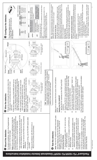
- 1. ❶ Mount the detector. ❷ Wire the detector. Tamper Switch Configure the detector. Microphone ❸ For location guidelines, refer to the Supplemental • Route the wire through the wire entry hole in the Power Tamper Information on the back page. PCB center. Cut and strip wire ends 1/4 inch 25 mA at Terminal Blocks The following tables show how to (6.0 mm). 12 VDC configure DIP switch S4 to best suit Note: If you plan to use the wall tamper, locate the the application. wall tamper screw position before the mounting • Wire the detector using 18-22 AWG (0.64 mm to LEDs Wire screws position. Refer to the Supplemental Informa- 1.02 mm). Reverse polarity connections will not Entry Hole tion for instructions on using the wall tamper. damage the detector. For proper wiring methods, = Default Settings refer to the National Electrical Code NFPA 70. • Use a screwdriver to push down on the latch at the SENSITIVITY1 SENS1 SENS2 APPROX. RANGE side of the detector to remove the front cover. • After completing wiring, push excess wire back Alarm Max OFF OFF 25’ (7.6 m) into the wall and replace the front cover. Form A DIP Switch Med ON OFF 15’ (4.6 m) Note: Do not remove the PCB from the protective Low OFF ON 10’ (3 m) Note: You can secure the cover with a #4 (2.9 mm) Lowest 5’(1.5 m) enclosure. ON ON screw if required. The hole is located on the interme- • For surface wiring, use the FG-SP2 spacer plate diate cover near the latch. FG-1625RT FG-1625RT FG-1625RT SWITCH OFF ON provided. FG-1625RT TB1 TB1 TB1 TB1 V+ V+ V+ V+ Red Alarm LED lights for Red Alarm LED latches TB2 TB2 TB2 • Secure the detector with #6 (3.5 mm) or V- TB2 V- V- V- 5 seconds during alarm. ON when detector goes NC TMPR NC TMPR NC TMPR LATCH NC TMPR into alarm.2,3 #8 (4.2 mm) screws (not provided). EOL EOL EOL EOL EOL EOL EOL EOL C C S4 ON TMPR C S4 ON TMPR C TMPR S4 ON TMPR S4 ON NO SENS1 NO SENS1 NO SENS1 NO SENS1 LEDs are disabled LEDs are always enabled. S3 S3 S3 SENS2 S3 SENS2 SENS2 SENS2 LATCH LATCH LATCH LATCH except during power-up LED TEST LED TEST LED TEST LED TEST LED No effect in Remote LED and Test Mode. 4 Enable/Disable Mode. FG-1625RT Only FG-1625RT Only FG-1625RT Only FG-1625RT Only 1 Verify range with the FG-701. NC loop, no EOL resistor NO loop, no EOL resistor NC loop with EOL resistor NO loop with EOL resistor 2 The timing of the alarm relay is not affected by the latched Alarm (FG-1625RT only) (FG-1625RT only) LED. 3 Reset the Alarm LED by removing and restoring power, or by TIP: Temporarily mount the detector in the intended toggling the detector in and out of test mode. 4 LEDs can be enabled or disabled with the FG-701. location and power it with a 9 V battery until testing establishes effective range coverage. If the 9 V battery is low, both LEDs will flash. Note: Some environmental factors may reduce the detector activation range. If after pressing the red start button you do not see the green ❹ Test the detector. LED flashing, move closer to the detector and try again. Note: Test the FG-1625R/RT at least once each year. Make sure to replace the front cover of the unit before Testing the Audio Alone Test the detector with the FG-701 Glassbreak testing. You can also use the simulator in the MANual mode to test audio alone. The green LED on the detector flickers when the Simulator. The FG-700 can be used if set for Testing the FG-1625R/RT detector properly receives the simulator audio. (See the FG-701 TEMPered glass sound. 1 Set the FG-701 switches to the TEST and FLEX Operating Instructions for additional information.) Keep in mind Activating Test Mode positions. this is not a complete test. 1 Position the simulator within 15’ (4.6 m) of the 2 Position the FG-701 near the farthest point of the Exiting Test Mode FG-1625R/RT detector. glass and point the speaker directly at the FG-1625R/ After testing, exit Test Mode using the same procedure for RT. If window coverings are present, close them fully activating Test Mode. The FG-1625R/RT automatically exits the 2 Switch the FG-701 simulator to ACTIVATE and Test Mode 5 minutes after the last event is detected. MANual modes. and hold the FG-701 behind them. 3 Press the red start button. The simulator “clicks” on REMOTE LED ENABLE/DISABLE MODE 3 Point the front speaker of the simulator at the and starts an 8 second armed period. The detector’s Remote LED Enable/Disable Mode allows you to detector and press the red start button. enable or disable the detector’s LEDs with the FG-701 Glassbreak The simulator buzzes, and the green LED on the 4 Generate a flex signal by carefully striking the glass Simulator. FG-1625R/RT flashes about once per second to with a cushioned tool. The FG-701 responds by To enable or disable the LEDs with the FG-701: indicate it is in Test Mode. producing a burst of glassbreak audio. 1. Set LED switch, S4 position 4, to off. If the FG-1625R/RT properly receives both the simulator 2. Enter Test Mode, and then exit Test Mode. If an FG-701 is not available, or if for any reason 3. Within two (2) seconds, enter Test Mode again; this changes remote activation cannot be used, use a small flex and audio, the red alarm LED lights. LED enable/disable status. screwdriver to short the test pads on the PCB. This 4. Exit Test Mode again. activates Test Mode. 5. Clap your hands to test the LEDs. If enabled, the green LED will flicker. If disabled, the green LED will remain off. FlexGuard® FG-1625R/FG-1625RT Glassbreak Detector Installation Instructions 5-051-738-00 Rev B 1
- 2. LOCATION GUIDELINES LED INDICATORS SPECIFICATIONS Range: ESD immunity: The FG-1625R/RT detects framed glass broken by an impact sufficient to make a The two LEDs on the front cover indicate the detector's operational status. The 25 feet (7.6 m) maximum 10 kV, Discharges of either polarity to exposed hole. Refer to the following guidelines when selecting a mounting location: following table summarizes the LED operation when the LEDs are enabled. No minimum range surfaces • The FG-1625R/RT can be mounted in corners, on walls, and on ceilings. Alarm relay: Dimensions: Condition Green LED Red LED FG-1625R Form A 4.25” OD x 0.88” THK • Mount within 25’ (7.6 m) of the glass. Normal OFF OFF FG-1625RT Form C (108 mm x 22.4 mm) 100 mA maximum • There is no minimum range, but the detector must have a clear line-of-sight and Normal, event detected Flicker OFF Weight: 25 VDC maximum a clear view of the glass. 4.5 oz., (128 g) Normal, break detected OFF ON 5 seconds ON/closed 22Ω ±6Ω Packaged product: 7.5 oz., (213 g) Normal, alarm latched OFF ON continuously OFF/open >1MΩ • The ideal location is on the wall or ceiling directly opposite the glass. The least Accessories: desirable location is on the same wall as the glass. Power up ON 1 second ON 1 second Alarm duration: FG-701 Glassbreak Simulator 5 seconds (unaffected by alarm LED Low voltage Flash ON/OFF Flash ON/OFF FG-SP2 Spacer Plate • When wall mounting, mount the detector a minimum of 6’ (1.8 m) high. latching) Test Mode Flash once per second OFF Approvals/Listings: • Curtains, blinds and other window coverings absorb energy from breaking Tamper switch: (FG-1625RT only) FCC and IC Verified Test Mode, event detected Flicker OFF Combination cover and wall tamper glass. Heavy curtains, for example, effectively block the sound signal. In these UL Listed 25 mA maximum cases, mount the detector on the window frame behind the window covering or Test Mode, alarm Flash once per second ON 5 seconds ULC Listed 24 VDC maximum above the window. CE Power requirements: FG-1625RT only: • Do not mount within 3’ (0.9 m) of forced air ducts, sirens, or bells measuring 2” 6 - 18 VDC; 12 mA typical at EN 50131-1, Grade 2, Class II Protected glass: 12 VDC, 22 mA max.; (5 cm) or more in diameter. Suitable for connection to an EN 60950 Class II Minimum size for all types is 11 inches (28 cm) square. Glass must be framed in the wall of AC Ripple: 4 Volts peak-to-peak the room or mounted in a barrier of 36 inches (0.9 m) minimum width. Limited Power Source • Minimize range to the glass. Do not install beyond the maximum specified range at nominal 12 VDC even if testing indicates greater range. Thickness RFI immunity: 30 V/m, 10 MHz - 1000 MHz • Adjust sensitivity for desired range; verify by testing with the FG-701. Type Minimum Maximum Plate3 3/32” (2 mm) Operating temperature: • Mounting on freestanding posts and pillars is not recommended. 3/8” (10 mm) 14° F to 131°F (-10° C to 55°C) Tempered 1/8” (3 mm) 3/8” (10 mm) UL: 14° F to 122°F (-10° C to 50°C) • Verify all installations back to the panel to be sure the protection loop is intact. Laminated1 1/8” (3 mm) 9/16” (14 mm) (Indoor use environment) Wired 1/4” (6 mm) 1/4” (6 mm) Storage: -4° F to 131° F (-20° C to 55° C) • Do not use outside. Coated2 1/8” (3 mm) 1/4” (6 mm) UL: -4° F to 122° F (-20° C to 50° C) • Avoid installing in rooms with high-level noise sources, such as air compressors, Sealed Insulating1,3 1/8” (3 mm) 1/4” (6 mm) bells, and power tools if those sources can be active when the detector can [1/2” (13 mm overall)] [3/4” (19 mm overall)] To obtain applicable EU compliance Declaration of Conformities for this product, please refer to signal an alarm. our Website http://www.security.honeywell.com/hsce/international/index.html. 1 For any additional information regarding the compliance of this product to any EU specific Protected only if both glass plates are broken. • Test false alarm immunity by activating any noise sources in the room. 2 requirements, please contact – Coated glass with security films up to 0.35mm (14 mils) thick (including films for solar protection) may be Quality Assurance Department, used. Evaluated with these products: 3M® SCOTCHSHIELD® SH14CLARL – 0.35mm (14 mils), 4 ply film; Honeywell Security & Custom Electronics, Note: The FG-1625R/RT detects shattering of framed glass by a direct impact. It Film Technologies International, Inc.’s GLASS-GARD® GGLL 1200 –0.3mm (12 mils), 3 ply film. Newhouse Industrial Estate, may not consistently detect breakage by blows that only crack the glass, by high 3 Motherwell, In compliance with Underwriters Laboratories of Canada’s Standard for Intrusion Detection Units (CAN/ Lanarkshire ML1 5SB, velocity projectiles (such as bullets) or if the glass is broken without an impact. ULC-S306-M89), ULC recognizes a maximum range for protecting sealed and insulated glass of Scotland, 3.8 m (12.5 ft). United Kingdom USING THE CEILING/WALL TAMPER SWITCH (FG-1625RT ONLY) Tel: +44(0)1698 738200 IMPORTANT: The FG-1625R/RT must be connected to a UL listed power supply or UL Email: UK64Sales@Honeywell.com The FG-1625RT has a combination normally-closed (NC) cover and wall tamper. listed control unit capable of providing a minimum of four hours of standby power. NOTICES Each detector is shipped with the cover tamper operational and the ceiling/wall FCC NOTICE: This device complies with Part 15 of the FCC Rules. Operation is subject to the following two conditions: (1) This device may not cause harmful interference, and (2) this device must accept any interference received, including tamper disabled. interference that may cause undesired operation. • Use needle-nose pliers to break out the plastic tab on the back of the The user is cautioned that changes or modifications not expressly approved by Honeywell could void the user’s authority to operate this equipment. detector. The tamper arm then extends through the hole. Rear Housing Note: This equipment has been tested and found to comply with the limits for a Class B digital device, pursuant to part 15 of the FCC Rules. These limits are designed to provide reasonable protection against harmful interference in a • The tamper screw (not provided) residential installation. This equipment generates, uses, and can radiate radio frequency energy and, if not installed and Tamper used in accordance with the instructions, may cause harmful interference to radio communications. However, there is should be a flat-head #8 (4.2 mm) or Cavity no guarantee that interference will not occur in a particular installation. If this equipment does cause harmful interference to radio or television reception, which can be determined by turning the equipment off and on, the user is encouraged #10 (4.8 mm) screw. to try to correct the interference by one or more of the following measures: 1) Reorient or relocate the receiving antenna, • Install the tamper screw so it will just 9.78 mm 2) Increase the separation between the equipment and receiver, 3) Connect the equipment into an outlet on a circuit (.385 in) different from that to which the receiver is connected. The installer can also consult an experienced radio/television make contact with the bottom of the technician for additional suggestions, if necessary. 4.2 mm or 4.8 mm IC Notice: This Class B digital apparatus complies with the Canadian ICES-003. mounted detector’s tamper cavity. (#8 or #10) Cet appareil numérique de la Classe B est conforme à la norme NMB-003 du Canada • After installing the tamper screw, Screw position the detector over it and mark FlexGuard® FG-1625R/FG-1625RT Glassbreak Detector Supplemental Information the locations for the mounting screws. Install screw to seat in tamper cavity © 2002 Honeywell International Inc. Honeywell and IntelliSense are registered trademarks of Honeywell P/N 5-051-738-00 Rev B 2 International Inc. All other trademarks are properties of their respective owners. All rights reserved.