1. WFD Series
Waterflow Detector
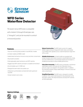
The System Sensor WFD series is compatible
with schedule 10 through 40 steel pipe, sizes
2˝ through 8˝, and can be mounted in a vertical
or horizontal position.
Robust Construction. The WFD series consists of a rugged,
Features
NEMA 4-rated enclosure. Designed for both indoor and outdoor
• Two-inch mounting hole provided in new WFD30-2 models use, the WFD series operates across a wide temperature range, from
32°F to 120°F.
• UL-listed models are NEMA 4 rated
• Sealed retard mechanism immune to dust and other contaminants Reliable Performance. UL-listed models are equipped with
tamper-resistant cover screws to prevent unauthorized entry. Inside,
• Visual switch activation
two sets of SPDT (Form C) synchronized switches are enclosed in a
• Field-replaceable retard mechanism and SPDT switches durable terminal block to assure reliable performance.
• Rugged, dual SPDT switches enclosed in a durable terminal block
False Alarm Immunity. The WFD series incorporates a mechanical
• Accommodates up to 12 AWG wire retard feature, which minimizes the risk of false alarm due to
pressure surges or air trapped in the sprinkler system. In addition,
• Designed for both indoor and outdoor use
the mechanical retard’s unique sealed design is immune to dust and
• 100 percent synchronization activates both alarm panel and other contaminants.
local bell
Simplified Operation. The WFD series is designed to simplify
• Tamper-resistant cover screws
installation. Two conduit openings permit easy attachment to the
local alarm system. The retard mechanism and dual SPDT switches
are field-replaceable.
Agency Listings
S739 CS169 7770-1653:114 167-93-E 3006195