Leviton vrs15 1 lz installation manual and setup guide
1. WARNINGS AND CAUTIONS:
• To be installed and/or used in accordance with appropriate electrical codes and regulations.
• If you are unsure about any part of these instructions, consult a qualified electrician.
• Vizia RF +™ electronic switches are not compatible with standard 3-way or 4-way switches. They must be used with compatible Vizia +™ or Vizia RF +™ controllers.
• Recommended minimum wall box depth is 2-1/2".
WARNINGS AND CAUTIONS:
• Use only one (1) Vizia RF +™ Scene Capable Switch in a multi-location circuit with up to 9 coordinating remotes (without LEDs) or up to 4 matching remotes
(with LEDs). The remote(s) will turn the load on (“at the level selected” for dimmers only) at the control.
• Maximum wire length from dimmer to all installed remotes cannot exceed 300 ft (90 m).
• Disconnect power at circuit breaker or fuse when servicing, installing or removing fixture.
• Use this device only with copper or copper clad wire. With aluminum wire use only devices marked CO/ALR or CU/AL.
Single Pole (One location) or 3-Way (Multi-location)
Scene Capable Electronic Switch
Cat. No. VRS15-1L, (Lighted) - 120VAC, 60Hz
Incandescent-1800W – Magnetic Low-Voltage-1800VA (1440W)
Electronic Low-Voltage-1800W – Fluorescent-1800VA – Supplemental-1/2 HP
INSTALLATION INSTRUCTIONS DI-000-VRS15-02A
Tools needed to install your Switch
Slotted/Phillips Screwdriver Electrical Tape Pliers
Pencil Cutters Ruler
Line up tabs and
press in sides one
at a time to attach
Push in
side at tab
to release
Changing the color of your Switch:
Your switch includes three color options. The switch ships with the White
frame attached. To change color of frame, proceed as follows:
INSTALLING YOUR SWITCH
NOTE: Use check boxes when Steps are completed.
WARNING: TO AVOID FIRE SHOCK OR DEATH; TURN
OFF POWER at circuit breaker or fuse and test that power is off
before wiring!
Step 1
2
4
3
1
Single Pole
1. Line (Hot)
2. Neutral
3. Ground
4. Load
2
4
1
5
3
3-Way
1. Line or Load (see
important instruction)
2. Neutral
3. Ground
4. First Traveler – note color
5. Second Traveler – note
color
Identifying your wiring application (most common):
NOTE: If the wiring in your wall box does not resemble any of
these configurations, consult a qualified electrician.
Step 2
IMPORTANT : For 3-Way applications, note that one of the screw terminals
from the old switch being removed will usually be a different color (Black)
or labeled Common. Tag that wire with electrical tape and identify as the
common (Line or Load) in both the switch wall box and remote wall box.
BK
RD
YL/RD
Terminal
Screw marked
Black (BK)
Terminal
Screw marked
Red (RD)
Terminal
Screw marked
Yellow/Red
(YL/RD)
Terminal Label:
Use Terminal for 3-Way or More Applications Only.
For Single-Pole Applications, Do Not Remove ThisLabel.
4
3
2
Terminal
Screw marked
White (WH)
1
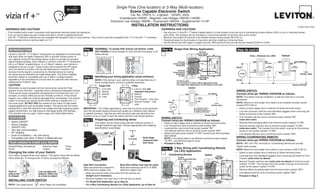
Single Pole Wiring Application:Step 4a
Step 3 Preparing and connecting wires:
This switch can be wired using side wire terminal screws or
through backwire openings. Choose appropriate wire stripping
specifications accordingly.
• Make sure that the ends of the wires from the wall box are
straight (cut if necessary).
• Remove insulation from each wire in the wall box as shown.
• For Single-Pole Application, go to Step 4a.
• For 3-Way Coordinating Remote (no LEDs) Application, go to Step 4b.
5/8"
(1.6 cm)
Strip Gage
(measure bare
wire here)Cut
(if necessary)
Side Wire Connection
Side wire terminals accept #14
AWG solid wire copper only.
Back Wire (either hole may be used)
Back wire openings use #14-12 AWG
solid wire copper only.
Hot (Black)
Neutral (White)
Load
Switch
BK
Black
White
RD
Green
Ground
YL/RD
Line
120VAC, 60Hz
Use Terminal for 3-Way or
More Applications Only.
For Single-Pole Applications,
Do Not Remove This Label.
WH
WIRING SWITCH:
Connect wires per WIRING DIAGRAM as follows:
• Green or bare copper wire in wall box to Green terminal screw.
• Line Hot wall box wire to terminal screw marked "BK".
• Load wall box wire to terminal screw marked "RD".
• Line Neutral wall box wire to terminal screw marked "WH".
• Switch terminal screw marked "YL/RD" should have Red insulation
label affixed.
NOTE: If insulating label is not affixed to terminal screw marked
"YL/RD", use electrical tape to cover.
• Proceed to Step 5.
Leviton’s Vizia RF +™ Z-Wave®
components are designed to communicate
with each other via Radio Frequency (RF) to provide remote control of
your lighting. Using RF technology allows Leviton to provide the greatest
signal integrity possible. Each module in Leviton’s Vizia RF +™ component
line is a Z-Wave®
enabled device. In a Z-Wave®
network, each device is
designed to act as a router. These routers will re-transmit the RF signal
from one device to another until the intended device is reached. This
ensures that the signal is received by its intended device by routing
the signal around obstacles and radio dead spots. The Scene Capable
Electronic Switch is compatible with any Z-Wave®
enabled network,
regardless of the manufacturer and can also be used with other devices
displaying the Z-Wave®
logo.
CAUTION:
Remember to exercise good common sense when using the Timer
features of your Remote – especially when scheduling unattended devices.
There can be some unexpected consequences if not used with care. For
example, an empty coffee pot can be remotely turned on. If that should
happen, your coffee pot could be damaged from overheating. If an electric
heater is turned on by remote control while clothing is draped over it, a
fire could result. DO NOT USE the remote for the control of high power
heating appliances such as portable heaters. This device will not control
lighting that is used with electronic low-voltage and high frequency power
supply transformers, nor high pressure discharge lamps (HID lighting).
This includes mercury-vapor, sodium vapor and metal halide lamps.
• Switch ON/OFF
• Scene Capable
• ON/OFF LED
• Two way communication
• RF reliability
• Ease of installation – No new wiring
• Compatible with other Z-Wave®
enabled devices
FEATURES
INTRODUCTION
BK
RD
WH
YL/RD
BK
RD
YL/RD
3
2
1
4
Terminal
Screw marked White (WH)
Terminal
Screw marked
Yellow/Red
(YL/RD)
5
Coordinating Remote Switch
4
3
1
5
Terminal
Screw marked
Red (RD)
Terminal
Screw marked
White (WH)
2
Terminal
Screw marked
Black (BK)
Terminal
Screw marked
Yellow/Red
(YL/RD)
Hot (Black)
Neutral (White)
Vizia + Remote (no LED)
YL/RD YL/RDRD
WH
RD
BK
Black
BKWH
White
Line
120VAC, 60Hz
Green
Ground
Green
Ground
(unused)
(unused)
Load
Switch
3-Way Wiring with Coordinating Remote
(no LED) Application:
Step 4b
Step 4b cont’d
WIRING SWITCH:
Connect wires per WIRING DIAGRAM as follows:
NOTE: The switch must be installed in a wall box that has a Line Hot
connection.
NOTE: Maximum wire length from switch to all installed remotes cannot
exceed 300 ft (90 m).
• Green or bare copper wire in wall box to Green terminal screw.
• Line Hot (common) wall box wire identified (tagged) when removing old
switch to terminal screw marked "BK".
• First Traveler wall box wire to terminal screw marked "RD"
(note wire color).
• Remove Red insulating label from terminal screw marked "YL/RD".
• Second Traveler wall box wire to terminal screw marked "YL/RD"
(note wire color). This traveler from the switch must go to the terminal
screw on the remote marked "YL/RD".
• Line Neutral wall box wire to terminal screw marked "WH".
WIRING COORDINATING REMOTE:
Connect wires per WIRING DIAGRAM as follows:
NOTE: "BK" and "RD" terminals on coordinating remote are unused.
Tighten both screws.
NOTE: Maximum wire length from switch to last remote is 300 ft (90 m).
• Green or bare copper wire in wall box to Green terminal screw.
• Load wall box wire identified (tagged) when removing old switch to First
Traveler (note color as above).
• Second Traveler wall box wire (note color as above) to terminal screw
marked "YL/RD". This traveler from the remote must go to the terminal
screw on the switch marked "YL/RD".
• Remove White insulating label from terminal screw marked "WH".
• Line Neutral wall box wire to terminal screw marked "WH".
• Proceed to Step 5.