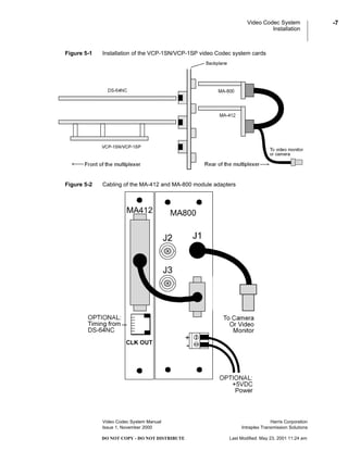
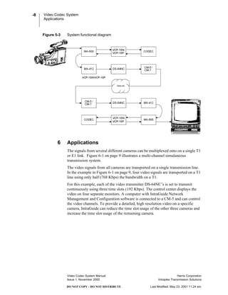
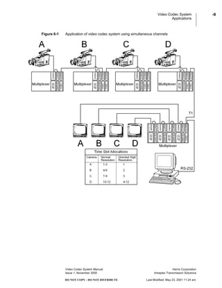
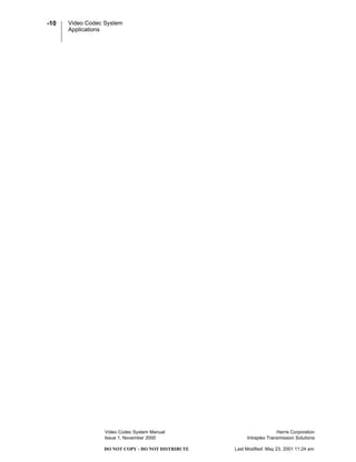
DO NOT COPY - DO NOT DISTRIBUTE Last Modified: May 23, 2001 11:24 am
© Copyright 2001 Harris Corporation.
All rights reserved.
Intraplex Video Codec System Manual
Issue 1, November 2000
Reproduction, adaptation, or translation without
prior written permission is prohibited, except as
allowed under the copyright laws.
Warranty
The information contained in this document is
subject to change without notice. Intraplex makes
no warranty of any kind with regard to this
material, including, but not limited to, the implied
warranties of merchantability and fitness for a
particular purpose.
Harris shall not be liable for errors contained
herein or for incidental or consequential damage in
connection with the furnishing, performance, or
use of this material.
Trademark Credits
IntraGuide™ is a trademark of Intraplex, Inc.
Other trademarks are the property of their
respective owners.
How to Contact Us
Harris Corporation
Intraplex Transmission Solutions
59 Porter Road
Littleton, Massachusetts 01460-1410
USA
Phone: +1 978 486 9000
Fax: +1 978 486 0660
E-mail: sales@intraplex.com
Web: http://www.intraplex.com
How to Get Support
If you have a technical question or issue with your
Intraplex equipment, please check our customer
support on our web site.
You can also send e-mail to:
support@intraplex.com
Harris Corporation
Intraplex Transmission Solutions
DO NOT COPY - DO NOT DISTRIBUTE Last Modified: May 23, 2001 11:24 am
Video Codec System
What is in this section?
1 Overview . . . . . . . . . . . . . . . . . . . . . . . . . . . . . . . . . . . . . . . . . . . . . . . . . 4
2 Components. . . . . . . . . . . . . . . . . . . . . . . . . . . . . . . . . . . . . . . . . . . . . . . 4
3 Controls . . . . . . . . . . . . . . . . . . . . . . . . . . . . . . . . . . . . . . . . . . . . . . . . . . 5
4 Power Requirement . . . . . . . . . . . . . . . . . . . . . . . . . . . . . . . . . . . . . . . . . 6
5 Installation . . . . . . . . . . . . . . . . . . . . . . . . . . . . . . . . . . . . . . . . . . . . . . . . 6
6 Applications. . . . . . . . . . . . . . . . . . . . . . . . . . . . . . . . . . . . . . . . . . . . . . . 8
Video Codec System
Overview
Video Codec System Manual Harris Corporation
Issue 1, November 2000 Intraplex Transmission Solutions
-4
DO NOT COPY - DO NOT DISTRIBUTE Last Modified: May 23, 2001 11:24 am
1 Overview
The Video Codec System is a two module set (DS-64NC plus VCP-1SN or
VCP-1SP) that allows transmission of standard video signals using an Intraplex
Access Server or CrossConnect Server. The VCP-1SN/VCP-1SP accepts a
standard NTSC/PAL video signal and compresses it for transmission. The
DS-64NC multiplexes the resulting digital signal onto a T1 or E1 path and also
provides for remote programming of the data rate. A matching set of modules at
the receiver de-multiplexes and decompresses the video signal. The output of the
receiver can be connected to a standard NTSC/PAL video monitor.
The Video Codec System occupies 3 card slots and can use from 1 to 24 timeslots
in a T1 stream or 1 to 31 timeslots in an E1 stream. The resolution and quality of
the video is set using switches on the VCP-1SN/VCP-1SP module. The
bandwidth occupied by the system determines the frame rate and is set either
through switches on the DS-64NC or remotely using IntraGuide configuration and
management software or ISiCL commands from a computer terminal. The data
rate can be changed by the user to match changing requirements.
2 Components
The Video Codec System contains the following components:
• VCP-1SN: This is a two-slot wide NTSC video Codec card. There is one
bank of switches on the board to select video settings. In addition there are
two toggle switches. These settings are not remotely programmable. See
Figure 3-1 on page 5 and Table 3-1 on page 6 for detailed descriptions of the
VCP-1SN settings.
• VCP-1SP: This is a two-slot wide PAL video Codec card. There is one bank
of switches on the board to select video settings. In addition there are two
toggle switches. These settings are not remotely programmable. See
Figure 3-1 on page 5 and Table 3-1 on page 6 for detailed descriptions of the
VCP-1SP settings.
• MA-800: This two-slot wide module adapter plugs in opposite the
VCP-1SN/VCP-1SP, providing three BNC connectors: one DB-9 connector
and a two-position terminal block. However, only one BNC-the video input or
video output-is active at this time. The DB-9 connector provides the RS-449
input connection to the DS-64NC. The terminal block is used for external
power, if required. (See Figure 2-1 on page 5.)
• DS-64NC: The DS-64NC is used to transport the RS-449 data generated by
the VCP-1SN/VCP-1SP over the T1 or E1. This module sets the speed of the
video, and is remotely programmable. Details on the installation and
operation of the DS-64NC are found in the DS-64NC Wideband Synchronous
Data Module Manual.
• MA-412: This is the standard RS-449 module adapter for the DS-64NC. (See
Figure 2-1 on page 5.)
• Video System Cable: A cable is supplied for inter-connection between the
MA-800 and MA-412 (see). It is six inches long with a DB-9 on one end and
a DB-37 on the other end. (See Figure 5-2 on page 7.)
Video Codec System
Controls
Video Codec System Manual Harris Corporation
Issue 1, November 2000 Intraplex Transmission Solutions
-5
DO NOT COPY - DO NOT DISTRIBUTE Last Modified: May 23, 2001 11:24 am
Figure 2-1 MA-412 and MA-800 module adapter ports
3 Controls
The VCP-1SN/VCP-1SP controls must be set before applying power. Figure 3-1
below shows the location of switches 1, 2, and 3 on the VCP-1SN/VCP-1SP. The
control settings are explained in Table 3-1 on page 6.
Figure 3-1 Top view of VCP-1SN/VCP-1SP, showing control switches
Video Codec System
Power Requirement
Video Codec System Manual Harris Corporation
Issue 1, November 2000 Intraplex Transmission Solutions
-6
DO NOT COPY - DO NOT DISTRIBUTE Last Modified: May 23, 2001 11:24 am
4 Power Requirement
A total of 1.75 Amps must be available from the +5V source in the multiplexer
chassis for each VCP-1SN/VCP-1SP. External +5V connections are available on
the MA-800 for systems where the current draw exceeds the capability of the
power supply.
5 Installation
The DS-64NC provides the point to point communications circuit for the
VCP-1SN/VCP-1SP module. The VCP-1SN/VCP-1SP will operate with any
bandwidth from 64 Kbps to 2.048 Mbps. The setup of the DS-64NC is discussed
in detail in the DS-64NC Wideband Synchronous Data Module Manual.
Note: The MA-412 module adapter must be set for an external clock (TT) for use
with a VCP-1SN/VCP-1SP.
Figure 5-1 on page 7 shows how the VCP-1SN/VCP-1SP is integrated into a
system with the MA-412 and MA-800 module adapters and the DS-64NC data
module on the Intraplex multiplexer bus. Figure 5-2 on page 7 provides the
cabling between the module adapters, and Figure 5-3 on page 8 illustrates a
functional block diagram of a VCP-1SN/VCP-1SP video system.
Table 3-1 Control settings on the VCP-1SN/VCP-1SP
Switch Setting Function
SW1 EXT Configures module for external +5V power.
INT Configures module for internal power.
SW2 ENCODER Configures module as an encoder (signal compression).
DECODER Configures module as a decoder (signal decompression).
SW3 ENC/DEC Configures module as encoder or decoder. Must match the
setting on SW2. DOWN = DECODER.
VIDEO SELECT 1 This switch must remain UP.
VIDEO SELECT 2 This switch must remain UP.
QUALITY 1 &
QUALITY 2
For encoder use only. Settings affect only low-speed
operations. This will affect image quality as follows:
Image Quality Quality 1 Switch Quality 2 Switch
BEST DOWN DOWN
VERY GOOD UP DOWN
GOOD DOWN UP
FAIR UP UP
RESOLUTION For encoder use only. Settings affect only low-speed
operations.
DOWN = 176x144 resolution
UP = 352x288 resolution
Video Codec System
Installation
Video Codec System Manual Harris Corporation
Issue 1, November 2000 Intraplex Transmission Solutions
-7
DO NOT COPY - DO NOT DISTRIBUTE Last Modified: May 23, 2001 11:24 am
Figure 5-1 Installation of the VCP-1SN/VCP-1SP video Codec system cards
Figure 5-2 Cabling of the MA-412 and MA-800 module adapters
Video Codec System
Applications
Video Codec System Manual Harris Corporation
Issue 1, November 2000 Intraplex Transmission Solutions
-8
DO NOT COPY - DO NOT DISTRIBUTE Last Modified: May 23, 2001 11:24 am
Figure 5-3 System functional diagram
6 Applications
The signals from several different cameras can be multiplexed onto on a single T1
or E1 link. Figure 6-1 on page 9 illustrates a multi-channel simulaneous
transmission system.
The video signals from all cameras are transported on a single transmission line.
In the example in Figure 6-1 on page 9, four video signals are transported on a T1
line using only half (768 Kbps) the bandwidth on a T1.
For this example, each of the video transmitter DS-64NC’s is set to transmit
continuously using three time slots (192 Kbps). The control center displays the
video on four separate monitors. A computer with IntraGuide Network
Management and Configuration software is connected to a CM-5 and can control
the video channels. To provide a detailed, high resolution video on a specific
camera, IntraGuide can reduce the time slot usage of the other three cameras and
increase the time slot usage of the remaining camera.
Video Codec System
Applications
Video Codec System Manual Harris Corporation
Issue 1, November 2000 Intraplex Transmission Solutions
-9
DO NOT COPY - DO NOT DISTRIBUTE Last Modified: May 23, 2001 11:24 am
Figure 6-1 Application of video codec system using simultaneous channels
Video Codec System
Applications
Video Codec System Manual Harris Corporation
Issue 1, November 2000 Intraplex Transmission Solutions
-10
DO NOT COPY - DO NOT DISTRIBUTE Last Modified: May 23, 2001 11:24 am

Harris_Intraplex Products_Video Codec_issue1

  • 1.
    DO NOT COPY- DO NOT DISTRIBUTE Last Modified: May 23, 2001 11:24 am
  • 2.
    DO NOT COPY- DO NOT DISTRIBUTE Last Modified: May 23, 2001 11:24 am © Copyright 2001 Harris Corporation. All rights reserved. Intraplex Video Codec System Manual Issue 1, November 2000 Reproduction, adaptation, or translation without prior written permission is prohibited, except as allowed under the copyright laws. Warranty The information contained in this document is subject to change without notice. Intraplex makes no warranty of any kind with regard to this material, including, but not limited to, the implied warranties of merchantability and fitness for a particular purpose. Harris shall not be liable for errors contained herein or for incidental or consequential damage in connection with the furnishing, performance, or use of this material. Trademark Credits IntraGuide™ is a trademark of Intraplex, Inc. Other trademarks are the property of their respective owners. How to Contact Us Harris Corporation Intraplex Transmission Solutions 59 Porter Road Littleton, Massachusetts 01460-1410 USA Phone: +1 978 486 9000 Fax: +1 978 486 0660 E-mail: sales@intraplex.com Web: http://www.intraplex.com How to Get Support If you have a technical question or issue with your Intraplex equipment, please check our customer support on our web site. You can also send e-mail to: support@intraplex.com
  • 3.
    Harris Corporation Intraplex TransmissionSolutions DO NOT COPY - DO NOT DISTRIBUTE Last Modified: May 23, 2001 11:24 am Video Codec System What is in this section? 1 Overview . . . . . . . . . . . . . . . . . . . . . . . . . . . . . . . . . . . . . . . . . . . . . . . . . 4 2 Components. . . . . . . . . . . . . . . . . . . . . . . . . . . . . . . . . . . . . . . . . . . . . . . 4 3 Controls . . . . . . . . . . . . . . . . . . . . . . . . . . . . . . . . . . . . . . . . . . . . . . . . . . 5 4 Power Requirement . . . . . . . . . . . . . . . . . . . . . . . . . . . . . . . . . . . . . . . . . 6 5 Installation . . . . . . . . . . . . . . . . . . . . . . . . . . . . . . . . . . . . . . . . . . . . . . . . 6 6 Applications. . . . . . . . . . . . . . . . . . . . . . . . . . . . . . . . . . . . . . . . . . . . . . . 8
  • 4.
    Video Codec System Overview VideoCodec System Manual Harris Corporation Issue 1, November 2000 Intraplex Transmission Solutions -4 DO NOT COPY - DO NOT DISTRIBUTE Last Modified: May 23, 2001 11:24 am 1 Overview The Video Codec System is a two module set (DS-64NC plus VCP-1SN or VCP-1SP) that allows transmission of standard video signals using an Intraplex Access Server or CrossConnect Server. The VCP-1SN/VCP-1SP accepts a standard NTSC/PAL video signal and compresses it for transmission. The DS-64NC multiplexes the resulting digital signal onto a T1 or E1 path and also provides for remote programming of the data rate. A matching set of modules at the receiver de-multiplexes and decompresses the video signal. The output of the receiver can be connected to a standard NTSC/PAL video monitor. The Video Codec System occupies 3 card slots and can use from 1 to 24 timeslots in a T1 stream or 1 to 31 timeslots in an E1 stream. The resolution and quality of the video is set using switches on the VCP-1SN/VCP-1SP module. The bandwidth occupied by the system determines the frame rate and is set either through switches on the DS-64NC or remotely using IntraGuide configuration and management software or ISiCL commands from a computer terminal. The data rate can be changed by the user to match changing requirements. 2 Components The Video Codec System contains the following components: • VCP-1SN: This is a two-slot wide NTSC video Codec card. There is one bank of switches on the board to select video settings. In addition there are two toggle switches. These settings are not remotely programmable. See Figure 3-1 on page 5 and Table 3-1 on page 6 for detailed descriptions of the VCP-1SN settings. • VCP-1SP: This is a two-slot wide PAL video Codec card. There is one bank of switches on the board to select video settings. In addition there are two toggle switches. These settings are not remotely programmable. See Figure 3-1 on page 5 and Table 3-1 on page 6 for detailed descriptions of the VCP-1SP settings. • MA-800: This two-slot wide module adapter plugs in opposite the VCP-1SN/VCP-1SP, providing three BNC connectors: one DB-9 connector and a two-position terminal block. However, only one BNC-the video input or video output-is active at this time. The DB-9 connector provides the RS-449 input connection to the DS-64NC. The terminal block is used for external power, if required. (See Figure 2-1 on page 5.) • DS-64NC: The DS-64NC is used to transport the RS-449 data generated by the VCP-1SN/VCP-1SP over the T1 or E1. This module sets the speed of the video, and is remotely programmable. Details on the installation and operation of the DS-64NC are found in the DS-64NC Wideband Synchronous Data Module Manual. • MA-412: This is the standard RS-449 module adapter for the DS-64NC. (See Figure 2-1 on page 5.) • Video System Cable: A cable is supplied for inter-connection between the MA-800 and MA-412 (see). It is six inches long with a DB-9 on one end and a DB-37 on the other end. (See Figure 5-2 on page 7.)
  • 5.
    Video Codec System Controls VideoCodec System Manual Harris Corporation Issue 1, November 2000 Intraplex Transmission Solutions -5 DO NOT COPY - DO NOT DISTRIBUTE Last Modified: May 23, 2001 11:24 am Figure 2-1 MA-412 and MA-800 module adapter ports 3 Controls The VCP-1SN/VCP-1SP controls must be set before applying power. Figure 3-1 below shows the location of switches 1, 2, and 3 on the VCP-1SN/VCP-1SP. The control settings are explained in Table 3-1 on page 6. Figure 3-1 Top view of VCP-1SN/VCP-1SP, showing control switches
  • 6.
    Video Codec System PowerRequirement Video Codec System Manual Harris Corporation Issue 1, November 2000 Intraplex Transmission Solutions -6 DO NOT COPY - DO NOT DISTRIBUTE Last Modified: May 23, 2001 11:24 am 4 Power Requirement A total of 1.75 Amps must be available from the +5V source in the multiplexer chassis for each VCP-1SN/VCP-1SP. External +5V connections are available on the MA-800 for systems where the current draw exceeds the capability of the power supply. 5 Installation The DS-64NC provides the point to point communications circuit for the VCP-1SN/VCP-1SP module. The VCP-1SN/VCP-1SP will operate with any bandwidth from 64 Kbps to 2.048 Mbps. The setup of the DS-64NC is discussed in detail in the DS-64NC Wideband Synchronous Data Module Manual. Note: The MA-412 module adapter must be set for an external clock (TT) for use with a VCP-1SN/VCP-1SP. Figure 5-1 on page 7 shows how the VCP-1SN/VCP-1SP is integrated into a system with the MA-412 and MA-800 module adapters and the DS-64NC data module on the Intraplex multiplexer bus. Figure 5-2 on page 7 provides the cabling between the module adapters, and Figure 5-3 on page 8 illustrates a functional block diagram of a VCP-1SN/VCP-1SP video system. Table 3-1 Control settings on the VCP-1SN/VCP-1SP Switch Setting Function SW1 EXT Configures module for external +5V power. INT Configures module for internal power. SW2 ENCODER Configures module as an encoder (signal compression). DECODER Configures module as a decoder (signal decompression). SW3 ENC/DEC Configures module as encoder or decoder. Must match the setting on SW2. DOWN = DECODER. VIDEO SELECT 1 This switch must remain UP. VIDEO SELECT 2 This switch must remain UP. QUALITY 1 & QUALITY 2 For encoder use only. Settings affect only low-speed operations. This will affect image quality as follows: Image Quality Quality 1 Switch Quality 2 Switch BEST DOWN DOWN VERY GOOD UP DOWN GOOD DOWN UP FAIR UP UP RESOLUTION For encoder use only. Settings affect only low-speed operations. DOWN = 176x144 resolution UP = 352x288 resolution
  • 7.
    Video Codec System Installation VideoCodec System Manual Harris Corporation Issue 1, November 2000 Intraplex Transmission Solutions -7 DO NOT COPY - DO NOT DISTRIBUTE Last Modified: May 23, 2001 11:24 am Figure 5-1 Installation of the VCP-1SN/VCP-1SP video Codec system cards Figure 5-2 Cabling of the MA-412 and MA-800 module adapters
  • 8.
    Video Codec System Applications VideoCodec System Manual Harris Corporation Issue 1, November 2000 Intraplex Transmission Solutions -8 DO NOT COPY - DO NOT DISTRIBUTE Last Modified: May 23, 2001 11:24 am Figure 5-3 System functional diagram 6 Applications The signals from several different cameras can be multiplexed onto on a single T1 or E1 link. Figure 6-1 on page 9 illustrates a multi-channel simulaneous transmission system. The video signals from all cameras are transported on a single transmission line. In the example in Figure 6-1 on page 9, four video signals are transported on a T1 line using only half (768 Kbps) the bandwidth on a T1. For this example, each of the video transmitter DS-64NC’s is set to transmit continuously using three time slots (192 Kbps). The control center displays the video on four separate monitors. A computer with IntraGuide Network Management and Configuration software is connected to a CM-5 and can control the video channels. To provide a detailed, high resolution video on a specific camera, IntraGuide can reduce the time slot usage of the other three cameras and increase the time slot usage of the remaining camera.
  • 9.
    Video Codec System Applications VideoCodec System Manual Harris Corporation Issue 1, November 2000 Intraplex Transmission Solutions -9 DO NOT COPY - DO NOT DISTRIBUTE Last Modified: May 23, 2001 11:24 am Figure 6-1 Application of video codec system using simultaneous channels
  • 10.
    Video Codec System Applications VideoCodec System Manual Harris Corporation Issue 1, November 2000 Intraplex Transmission Solutions -10 DO NOT COPY - DO NOT DISTRIBUTE Last Modified: May 23, 2001 11:24 am