Download as PDF, PPTX

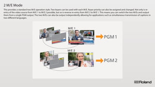


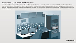


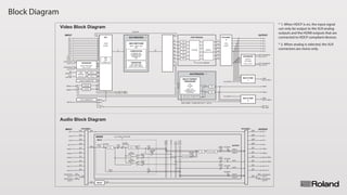


The document describes various operation modes of the V-1200HD video switcher, including different modes for keyers and mixing operations to accommodate a range of video production needs. It highlights features such as multi-format capability, extensive audio mixing, memory banks for quick presets, and advanced scaling for improved image quality. Additionally, the V-1200HD supports multiple applications in broadcast, live performance, and event production, allowing for versatile video switching and routing functionalities.


