Download to read offline


![References 73
4.20 E. Chesson, Jr., W. H. Munse, R. L. Dineen, and J. G. Viner, “Performance of Nuts
on High-Strength Bolts,” Fasteners, Vol. 21, No. 3, 1967.
4.21 C. F. Krickenberger, Jr., E. Chesson, Jr., and W. H. Munse, Evaluation of Nuts for Use
with High-Strength Bolts, Structural Research Series, No. 128, University of Illinois,
Urbana, January 1957.
4.22 J. N. Macadam, Research on Bolt Failures in Wolf-Creek Structural Plate Pipe, Research
Center Armco Steel Corporation, Middletown, Ohio, 1966.
4.23 W. K. Boyd and W. S. Hyler, “Factors Affecting Environmental Performance of High-
Strength Bolts,” Journal of the Structural Division, ASCE, Vol. 99, ST7, July 1973.
4.24 Subcommittee on Bolt Strength, “Delayed Fracture of High-Strength Bolts,” Society of
Steel Construction of Japan, Vol. 6, No. 52, Tokyo, June 1970.
4.25 J. J. Wallaert and J. W. Fisher, “What Happens to Bolt Tension in Large Joints,”
Fasteners, Vol. 20, No. 3, 1965.
4.26 R. N. Allan and J. W. Fisher, “Bolted Joints with Oversize and Slotted Holes,” Journal of
the Structural Division, ASCE, Vol. 94, ST9, September 1968.
4.27 W. H. Munse, The Case for Bolted Galvanized Bridges, American Hot Dip Galvanizers
Association, Inc., Washington, D. C., May 1971.
4.28 J. H. A. Struik, A. 0. Oyeledun, and J. W. Fisher, “Bolt Tension Control with a Direct
Tension Indicator,” Engineering Journal, AISC, Vol. 10, No. 1, 1973.
4.29 W. S. Hyler, K. D. Humphrey, and N. S. Croth, An Evaluation of the High Tensile Huck-
Bolt Fastener for Structural Applications, Report 72, Huck Manufacturing Co., Detroit,
Michigan, March 1961.
4.30 American Society for Testing and Materials, High-Strength Bolts for Structural and Steel
Joints [Metric] , ASTM Designation A325M-84a, Philadelphia, 1985.
4.31 European Convention for Constructional Steelwork (ECCS), European
Recommendations for Bolted Connections in Structural Steelwork, 4th
Ed., Brussels,
November 1983.
4.32 Commission of European Communities (CEC), Eurocode 3, Common Unified Code of
Practice for Steel Structures, Brussels, November 1983..
4.33 Swiss Society of Engineers and Architects, SIA 161, Steel Structures, Zürich
4.34 International Standards Organization, Steel Construction—Materials and Design,
Document ISO/TC 167/SCI N132, Geneva, 1986.
4.35 J. W. Fisher, B. Kato, H. M. Woodward, and K. H. Frank, Field Installation of High
Strength Bolts in North America and Japan, IABSE Surveys S-8/79, IABSE, Zurich,
1979.
4.36 “Short Grip High-Strength Bolts,” unpublished report, University of Illinios, Urbana,
May 1979.
4.37 J. W. Fisher, Private communication, April 1984.
4.38 H. E. Townsend, Jr., “Effects of Zinc Coatings on the Stress Corrosion Cracking and
Hydrogen Embrittlement of Low-Alloy Steel,” Metallurgical Transactions A, Vol.
6A, April 1975.](https://image.slidesharecdn.com/guidetorcsc-2004-231113121445-38609d12/85/Guide-to-RCSC-2004-pdf-87-320.jpg)
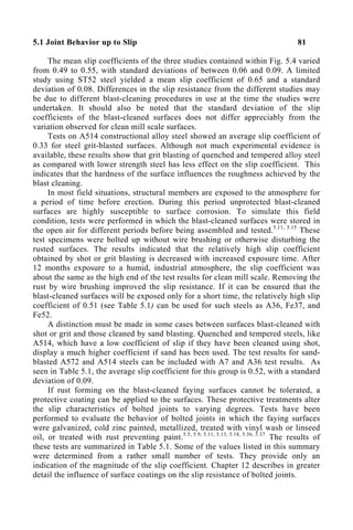
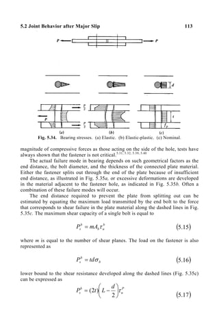
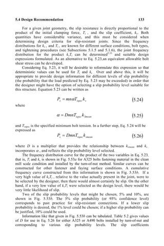
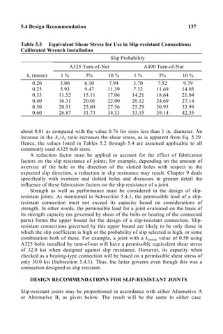
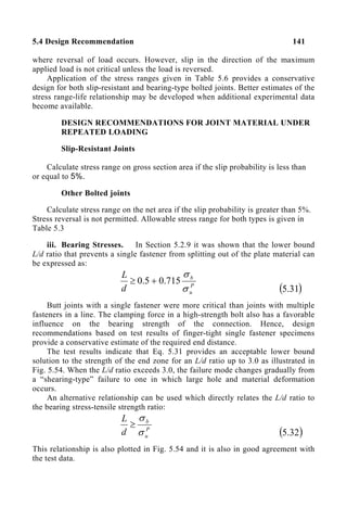
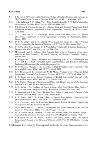
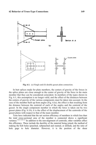
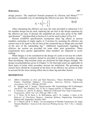
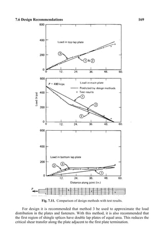
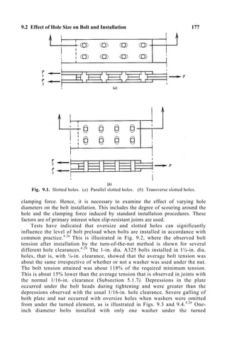
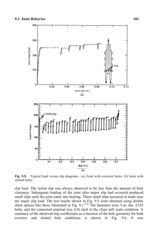

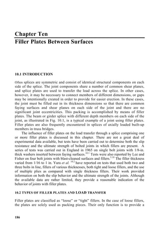
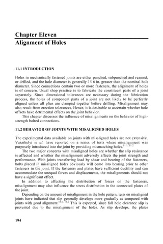
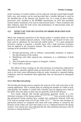
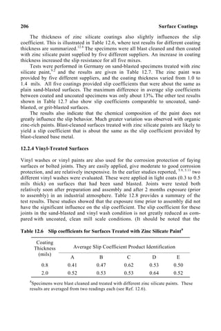
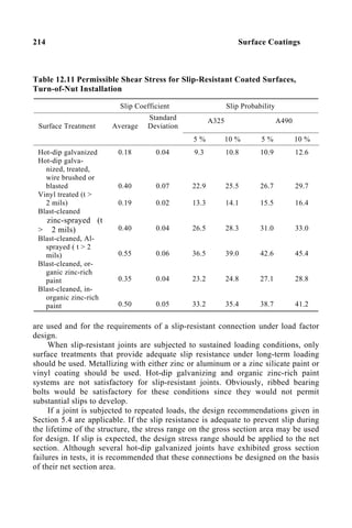
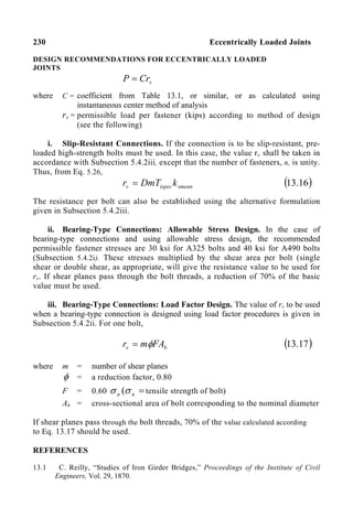
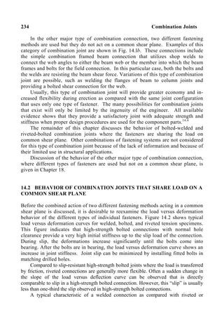
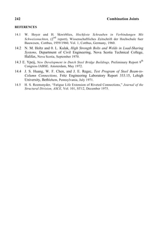

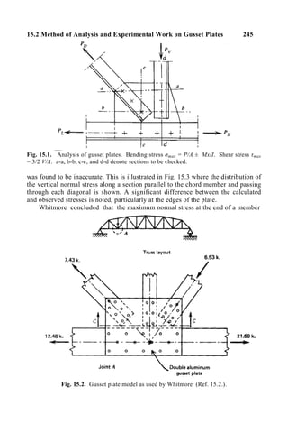
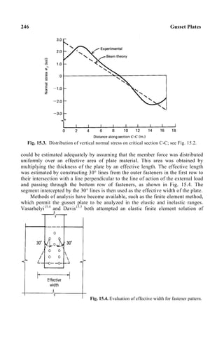
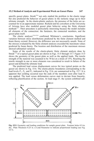
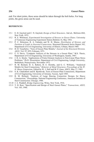
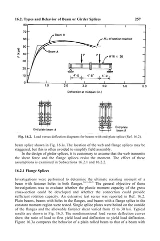
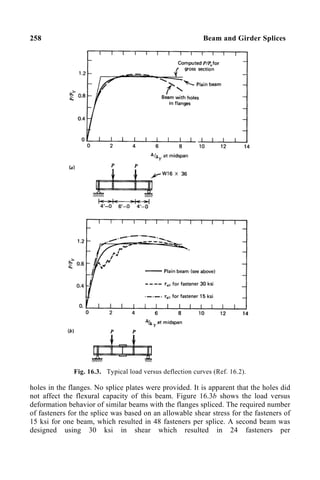
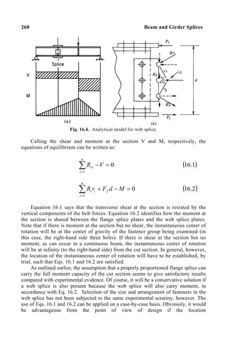
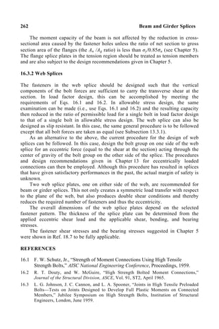
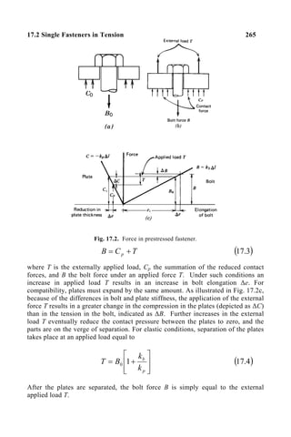
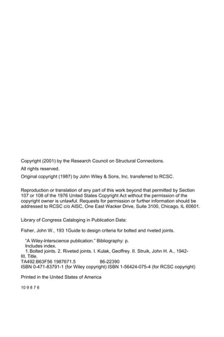
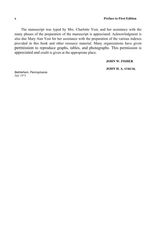
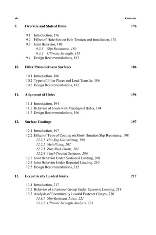
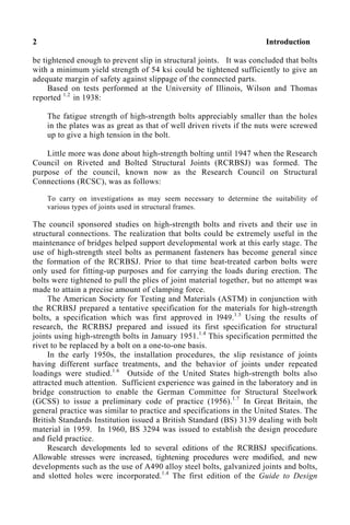
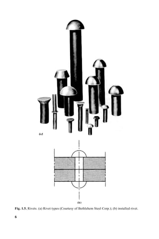
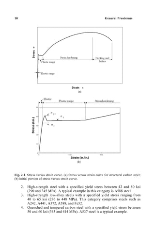
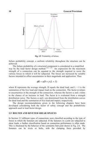
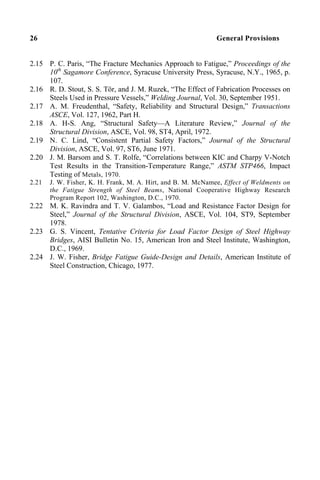
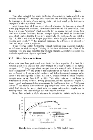
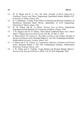
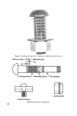
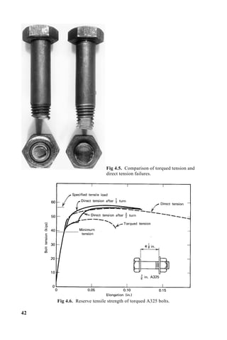
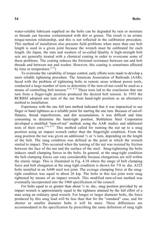
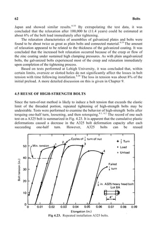
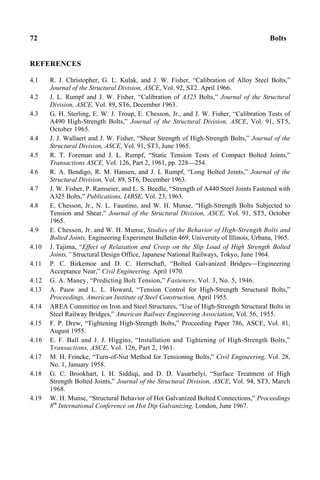
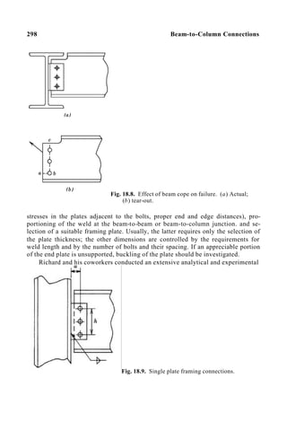
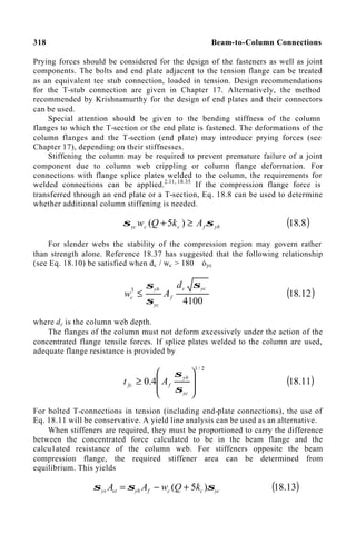
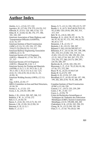
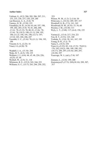
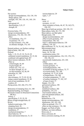
![17.5 Analysis of Prying Action 275
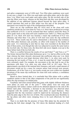
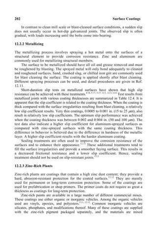
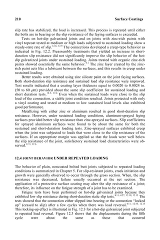
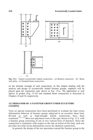
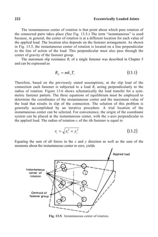
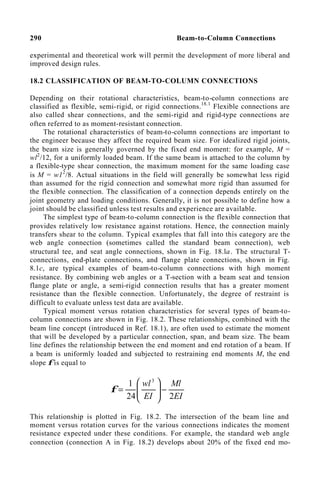
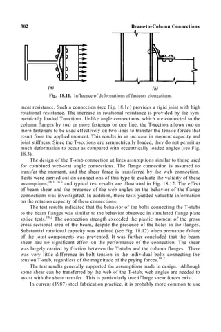
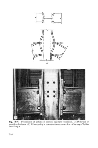
in Fig. 17.12 and suggested a formula based on an elastic analysis. They
considered the properties of the bolts and the connected material and the geometry
of the connection. These formulas were then modified to simplify application and
reflect test results. The following semi-empirical equation was obtained.
( )
( )
[ ] ( ) T
A
ab
wt
b
a
b
a
A
ab
wt
Q
b
b
+
+
−
= 2
4
2
4
2
1
6
/
1
3
/
30
/
( )
5
.
17
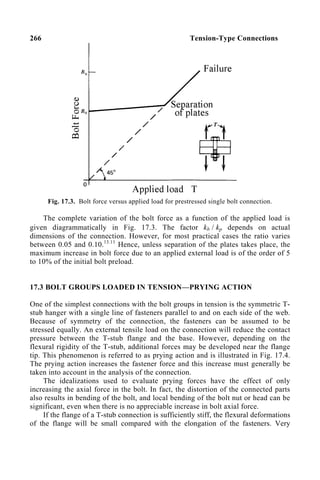
This equation relates the prying force Q to the ultimate load of the connection. A
similar formula with different coefficients was suggested for evaluating the prying
force under working load conditions.16.2
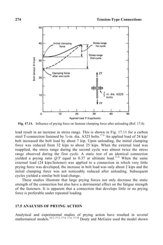
The development of Eq. 17.5 by Douty and McGuire was based on the
fulfillment of both equilibrium and compatibility conditions. The latter was
obtained by assuming that the T-stub flange acts as a simple beam between its tips,
acted upon by the bolt forces and the applied load. The flange deflection at the bolt
line was equated to the axial deflection of the bolt and the flange expansion in the
thickness direction due to reduction in contact pressure. For this compatibility
statement to be valid, both the T-stub flange and the bolt must remain elastic and
the flange must continue to act with a span of 2(a + b). Although the first condition
may be met approximately under working load conditions, it is unlikely to be valid
at the time that the ultimate load of the connection is reached. The second
condition, which in effect says that the force Q acts uniquely at the flange tips, is
not likely to be satisfied at any load level, although the effect of this inaccuracy
cannot be determined.
Agerskov17.10
has presented a development for the prediction of prying action
that is similar in some major respects to that of Douty and McGuire. He also used
both equilibrium and compatibility equations to develop a prediction of prying
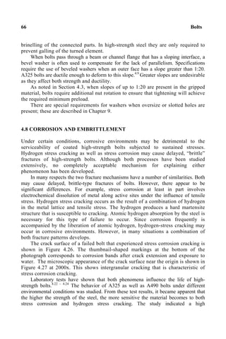
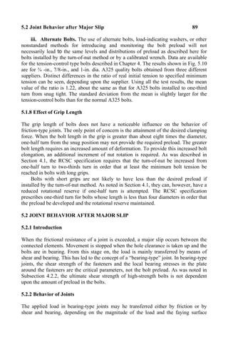
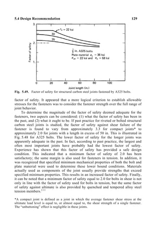
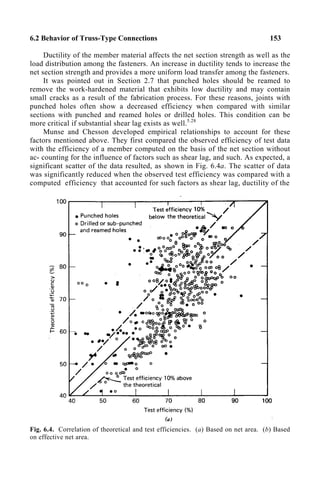
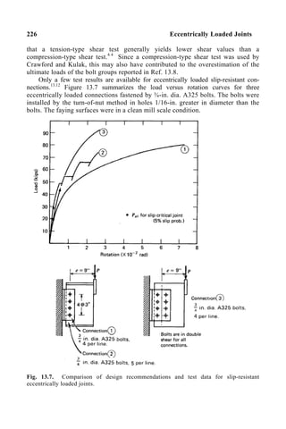
Fig. 17.12. Model used by Douty and McGuire (Ref. 16.2).](https://image.slidesharecdn.com/guidetorcsc-2004-231113121445-38609d12/85/Guide-to-RCSC-2004-pdf-290-320.jpg)
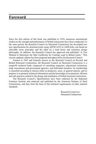
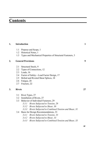
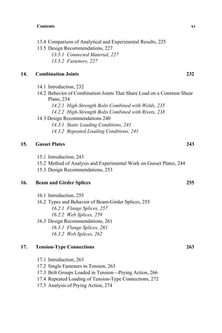
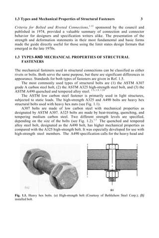
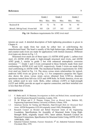
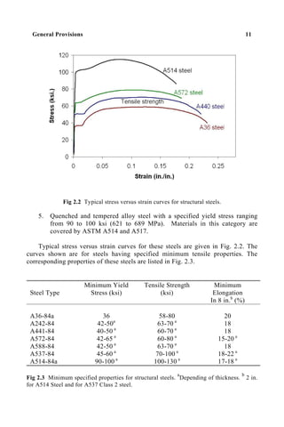
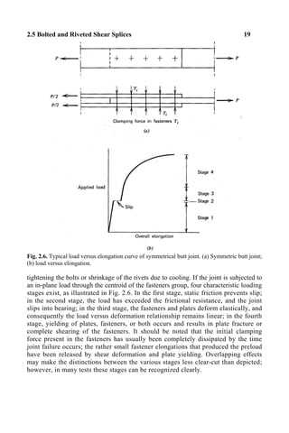
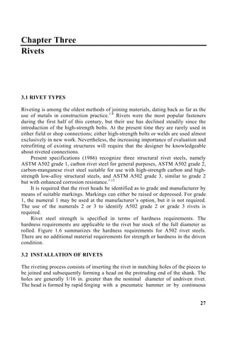
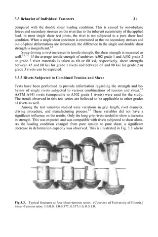
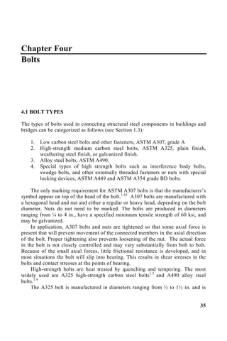
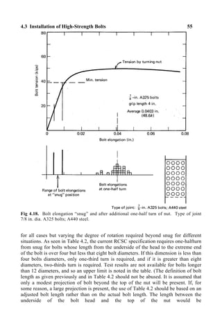
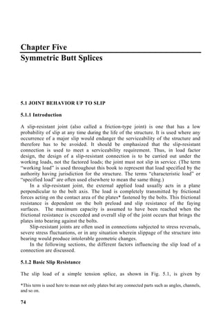
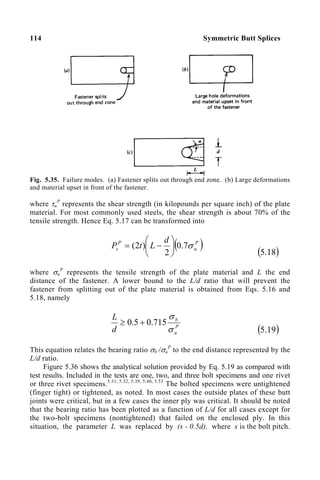
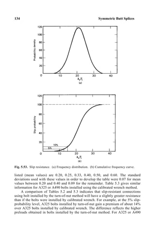
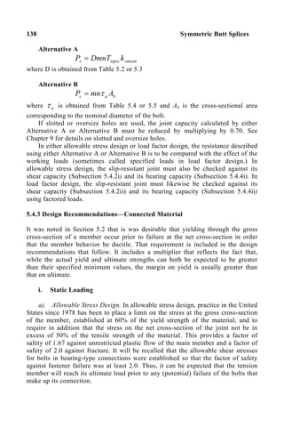
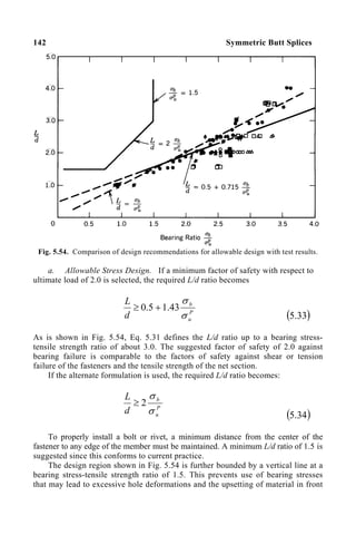
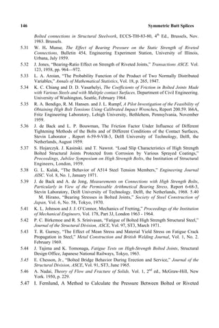
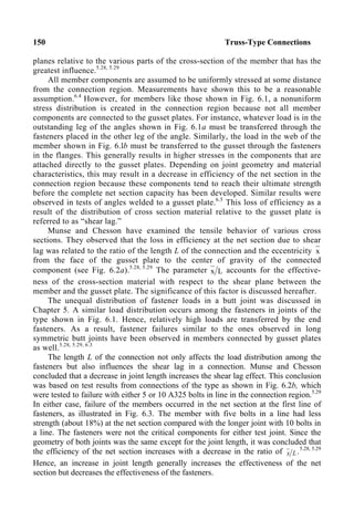
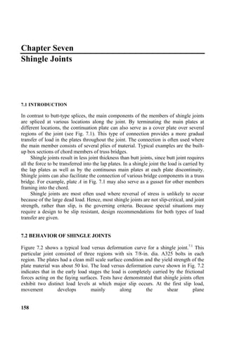
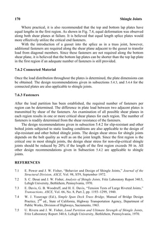
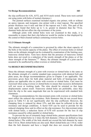
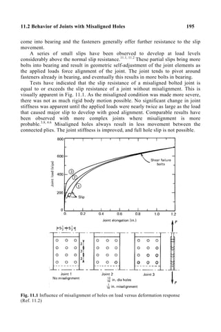
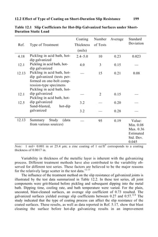
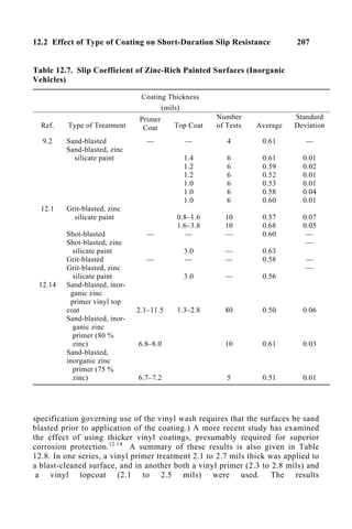
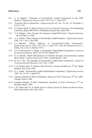
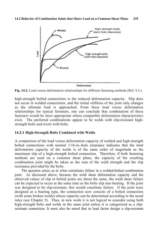
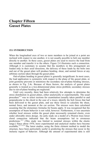
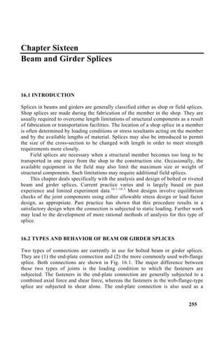
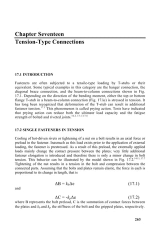
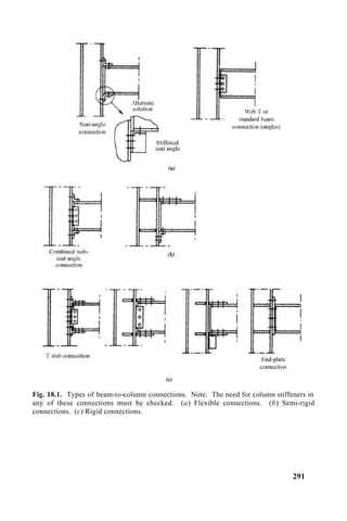
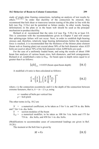
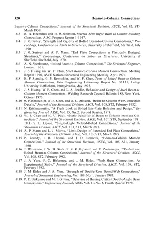
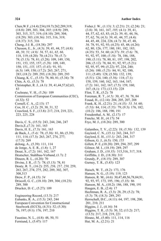
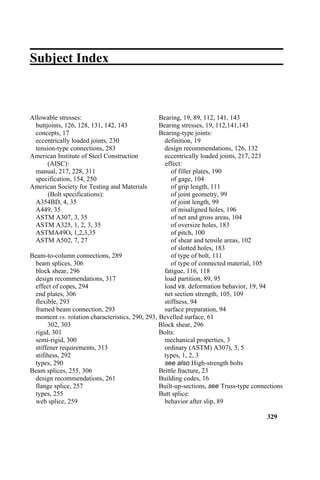
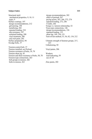
![17.5 Analysis of Prying Action 279
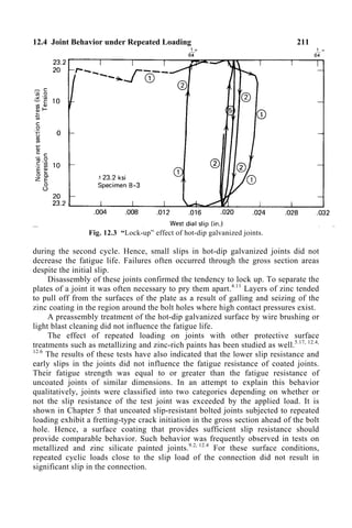
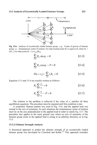
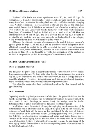
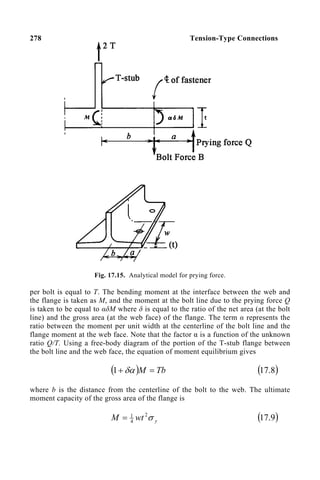
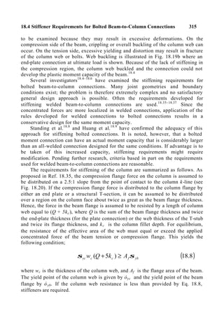
where σy is the yield strength of the flange material, t is the flange thickness, and w
the length of the flange parallel to the web that is tributary to each bolt (see Fig.
17.15).
Another equation can be obtained by writing the moment equilibrium
requirement for the portion of the flange between the bolt line and the flange tip:
y
wt
Qa σ
αδ 2
4
1
= ( )
10
.
17
Equilibrium of applied load, bolt force, and prying force requires that
Q
T
B +
= ( )
a
10
.
17
When expressed in terms of the other moment and equilibrium conditions, this
results in
( )
+
+
=
a
b
T
B
δα
δα
1
1 ( )
11
.
17
and
( )
[ ]
2
/
1
4
+
+
=
b
a
a
w
Bab
t
y αδ
σ
( )
12
.
17
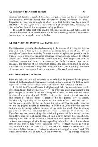
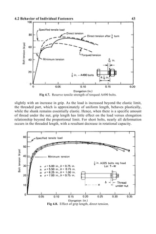
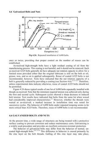
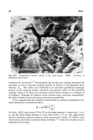
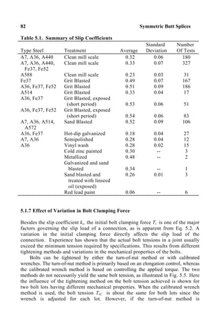
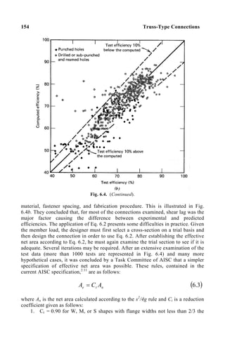
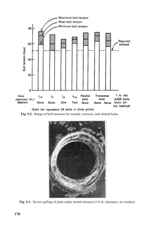
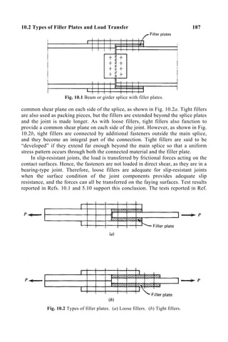
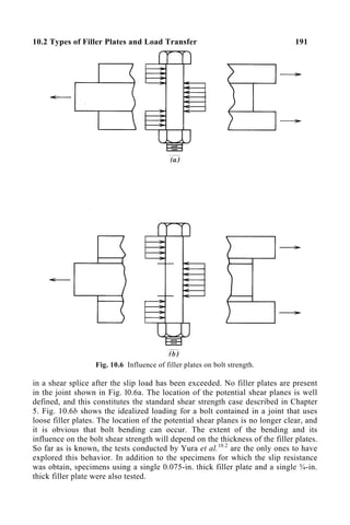
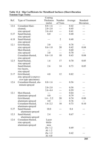
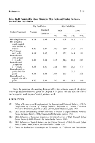
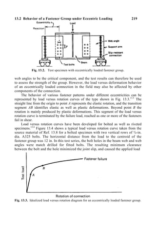
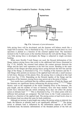
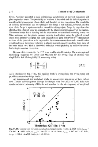
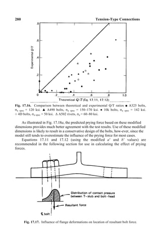
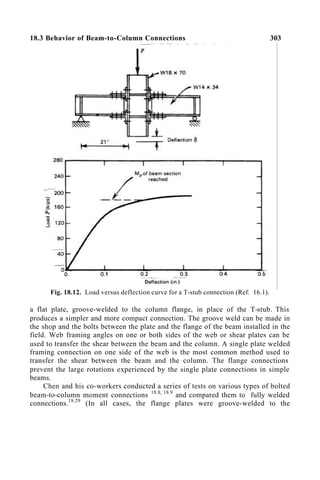
Equation 17.12 relates the required flange thickness to the mechanical properties and
geometrical dimensions of the constituent parts of the connection. Experimental results
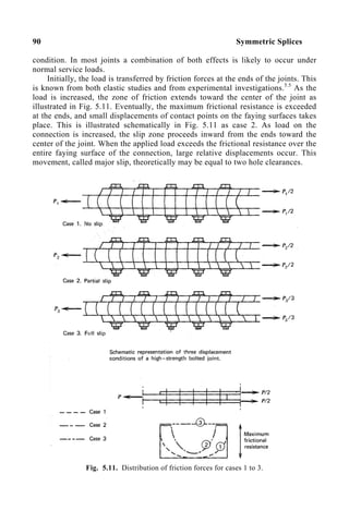
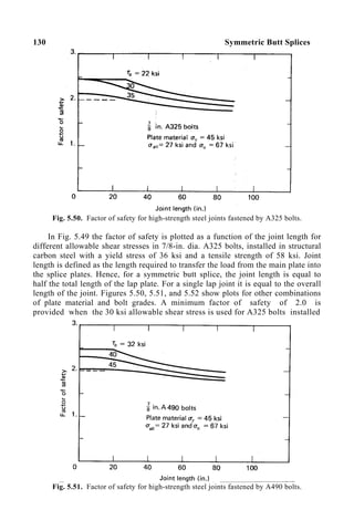
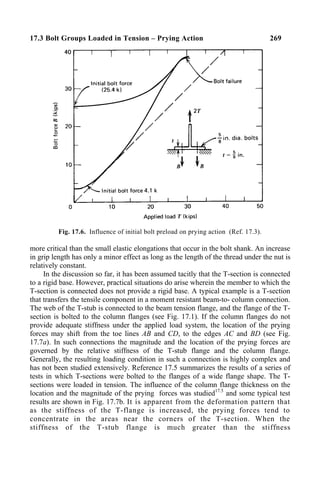
and the prying ratio Q/T obtained from Eq. 17.11 are compared in Fig. 17.16 for
different types of bolts. A few data obtained from riveted specimens are included as
well.
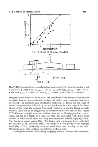
It is apparent that the solution given by Eqs. 17.11 and 17.12 overestimates the
prying force. The variation is comparable to that obtained when Eqs. 17.6 and 17.7
are used. Among the factors causing the difference between the load transfer
predicted by the idealized model and the test results are strain-hardening and the
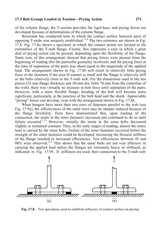
actual distribution of forces. The model assumes the bolt force to act at the
centerline of the bolt. As a result of flexural deformations in the flange, the bolt B
force is acting probably somewhere between the bolt axis and the edge of the bolt
head, as indicated in Fig. 17.17. This decreases the distance b and changes the
prying ratio Q/T directly. To approximate this effect, a revised equilibrium
condition was developed using modified distances a’ and b’, defined in Fig.
17.18b. The resultant fastener force B was assumed to act at a distance b’ equal to
b – d/2 from the web face. The distance a’ was taken equal to a + d/2. The model
assumes the prying force Q at ultimate load to be a line load at the tip of the flange.
Tests have indicated that this is a reasonable assumption as long as the end
distance is not much greater than the distance b. Therefore, it is recommended that
the end distance a be limited to 1.25b.](https://image.slidesharecdn.com/guidetorcsc-2004-231113121445-38609d12/85/Guide-to-RCSC-2004-pdf-294-320.jpg)
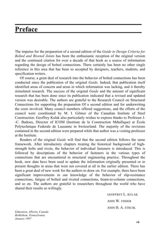
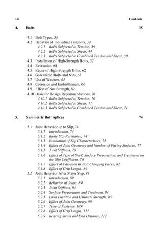
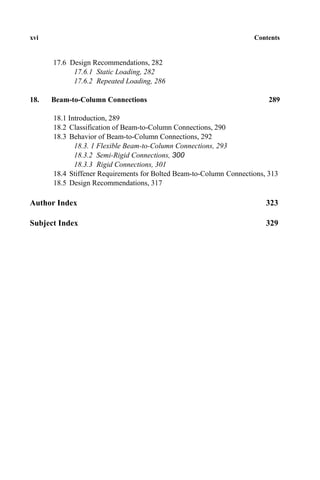
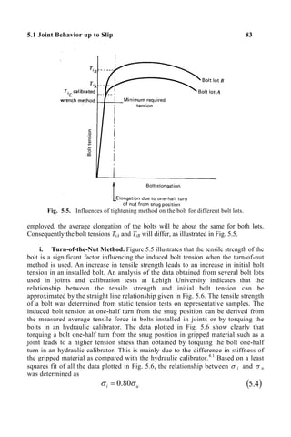
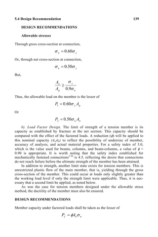
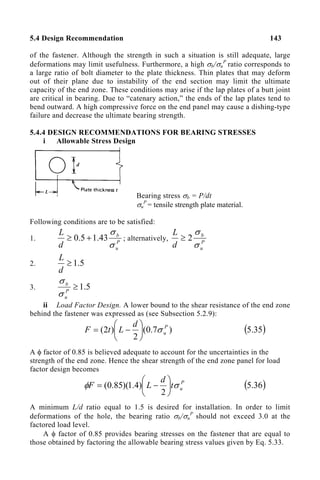
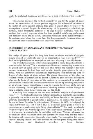
![284 Tension-Type Connections
and Eq. 17.12 can then be used to determine whether or not the trial flange
thickness is adequate. The value of B in Eq. 17.12 is to be taken as the permissible
fastener load.
If the value of α determined using Eq. 17.11 exceeds unity, this indicates that
the limiting condition has been reached. For this case, the ultimate load of the
connection would be attained when plastic hinges form at the bolt lines and at the
web-to-flange junction. In this situation, the force in the bolts at working load
levels can be determined directly from Eq. 17.11 using α = 1.0. In order to check
the plate thickness (Eq. 17.12), the force in the bolts should be that corresponding
to ultimate load levels. Hence, B is now to be taken as 2.0 times that established
using Eq. 17.11.
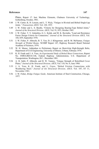
It was noted in Section 17.5 that better agreement between test results and
predictions made using Eqs. 17.11 and 17.12 was obtained if the distances a and b
are modified as indicated in Fig. 17.18. Thus, for convenience, Eqs. 17.11 and
17.12 will be restated in the Design Recommendations For T-Connections Under
Static Loading Conditions using the equality form and the modified geometry
parameters.
DESIGN RECOMMENDATIONS FOR T-CONNECTIONS UNDER
STATIC LOADING CONDITIONS
Allowable Stress Design
Allowable tensile load per fastener
uspec
b
all A
B σ
375
.
0
=
Check adequacy of fastener to resist the applied load and prying action:
Q
T
Ball +
≥
or upon substituting Eq. 17.11 with modified a and b distances;
( )
+
+
≥ '
'
1
1
a
b
T
Ball
δα
δα
( )
17
.
17
The T-flange thickness must be equal to or exceed
( )
[ ]
2
/
1
'
'
'
'
'
4
+
+
=
b
a
a
w
b
a
B
t
y αδ
σ
( )
18
.
17
where 2
/
'
d
a
a +
=
2
/
'
d
b
b −
=
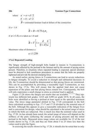
=
B estimated fastener load at failure of the connection
if a < 1.0](https://image.slidesharecdn.com/guidetorcsc-2004-231113121445-38609d12/85/Guide-to-RCSC-2004-pdf-299-320.jpg)
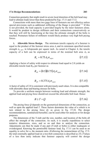
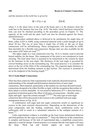
![17.6 Design Recommendations 285
u
b
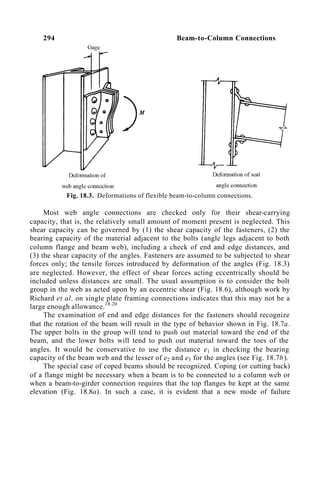
A
B σ
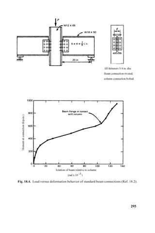
75
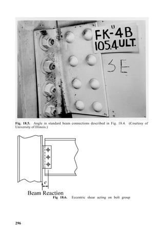
.
0
=
if ,
0
.
1
≥
α it is taken as 1.0 and
( )
+
+
= '
'
1
1
2
a
b
T
B
δ
δ
Maximum value of distance a
b
a 25
.
1
≤
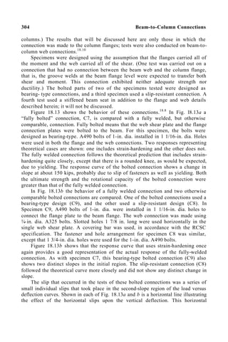
The design recommendations given in this section are valid for tension-type
connections fastened to a rigid base. It was noted in Section 17.3 that the stiffness
of the base to which the T-section is connected is an important parameter in the
development of prying forces. If the base does not provide enough stiffness, the
fastener loads and prying forces should be evaluated on the basis of the
geometrical dimensions and material properties of the flange to which the T is
connected. The joint component that provides the least stiffness results in the
greatest prying forces and governs the design of the fasteners.
ii. Load Factor Design. The design of T-connections by load factor design
is directly comparable to allowable stress design. The only difference is that the
load on the fastener at the factored load level should not exceed the ultimate tensile
load of the fastener multiplied by a reduction factor φ. A reduction factor φ equal
to 0.85 is in reasonable agreement with past practice. A load factor of 1.7 and a
reduction factor of 0.85 yields a design that is comparable to allowable stress
design.
DESIGN RECOMMENDATIONS FOR T-CONNECTIONS UNDER
STATIC LOADING CONDITIONS
Load Factor Design
Maximum tensile capacity of fastener
u
b
A
B σ
75
.
0
=
Check adequacy of fastener to resist the applied load as well as prying action
( )
+
+
≥ '
'
'
1
1
a
b
T
B
δα
δα
φ
where the reduction factor ф = 0.85 and represents the applied load per fastener at
the factored level. The T-flange thickness is given by
( )
[ ]
2
/
1
'
'
'
'
'
4
+
+
=
b
a
a
w
b
a
B
t
y αδ
σ](https://image.slidesharecdn.com/guidetorcsc-2004-231113121445-38609d12/85/Guide-to-RCSC-2004-pdf-300-320.jpg)
![References 319
If C1 = yc
yb σ
σ and C2 = ys
yc σ
σ , Eq. 18.13 can be expressed as:
[ ] 2
1 )
5
( C
k
Q
w
A
C
A c
c
f
st +
−
= ( )
a
13
.
18
If Eq. 18.12 governs the column web thickness, the required area becomes:
yc
yc
c
c
f
st
d
w
A
C
A σ
σ
−
=
3
1
4100
( )
14
.
18
A comparable requirement can be developed for stiffeners opposite the tension
flange by considering the needed additional flange area to be resisted by stiffeners.
Equilibrium yields
'
f
yb
f
yb
st
ys A
A
A σ
σ
σ −
= ( )
15
.
18
where Af óyb is the actual beam flange tension force, and Af’óyb is the beam flange
tension force that would not require stiffeners. This latter force can be estimated
from Eq. 18.11 for the column flange thickness furnished. This yields
2
2
'
6
16
100
fc
yb
yc
fc
yb
yc
f t
t
A
σ
σ
σ
σ
≅
=
Substitution into Eq. 18.15 yields
2
6 fc
yb
f
yb
st
ys t
A
A σ
σ
σ −
= ( )
a
15
.
18
Hence, the required stiffener area opposite the team tension flange becomes
[ ] 2
2
1 6 C
t
A
C
A fc
f
st −
= ( )
b
15
.
18
As a practical requirement, if stiffeners are required opposite both the beam
tension and compression flanges, they are generally made the same size.
The fastener shear stresses and the bearing stresses suggested in Chapter 5 were
shown in Refs. 18.7, 18.9, and 18.36 to be fully applicable to beam-to-column
connections.
REFERENCES
18.1 J. C. Rathbun. “Elastic Properties of Riveted Connections,” Transactions, ASCE,
Vol. 101. 1936.
18.2 W. H. Munse. W. 0. Bell and E. Chesson. Jr., “Behavior of Riveted and Bolted](https://image.slidesharecdn.com/guidetorcsc-2004-231113121445-38609d12/85/Guide-to-RCSC-2004-pdf-334-320.jpg)


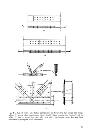
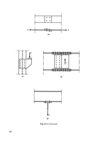
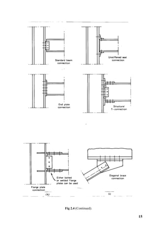
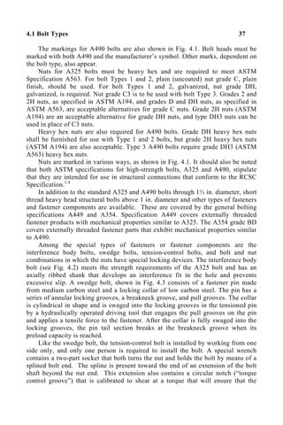
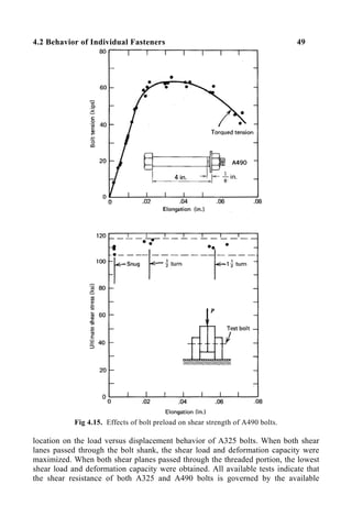
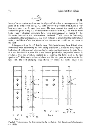
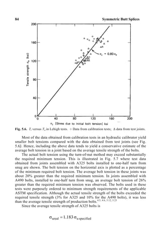
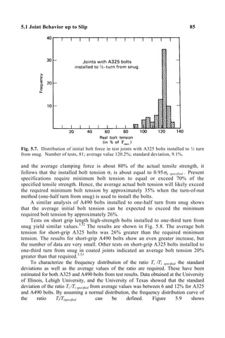
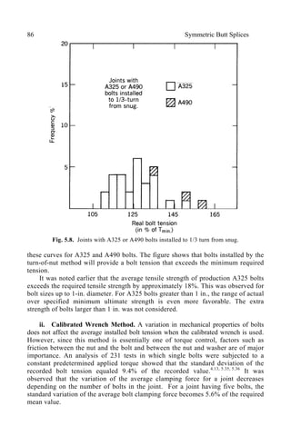
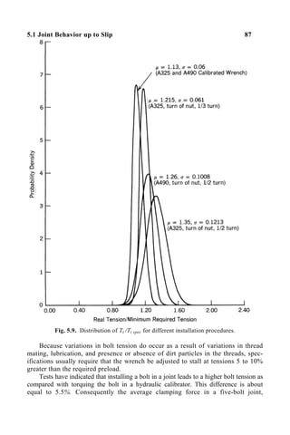
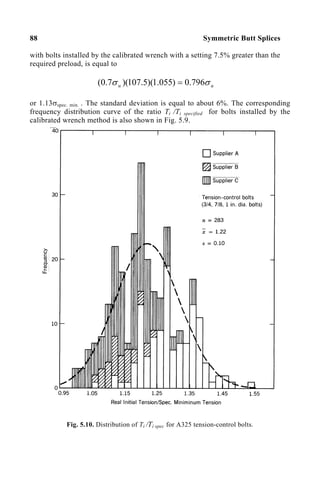
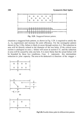
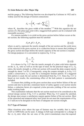
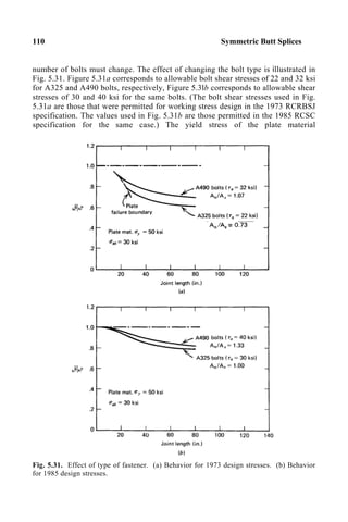
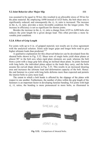
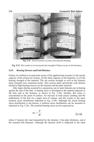
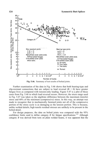
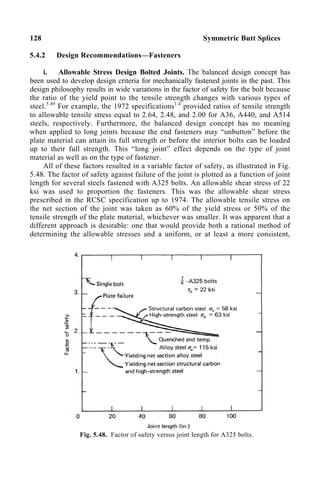
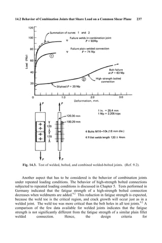
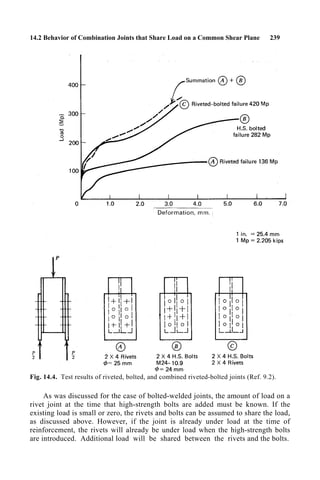
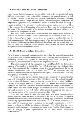
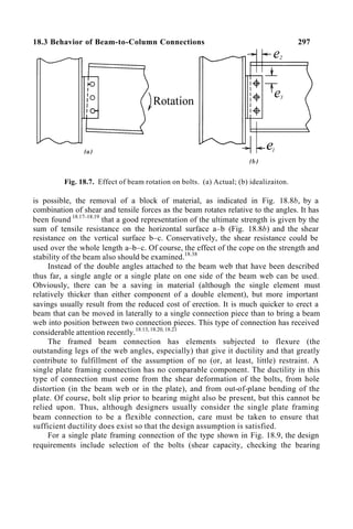
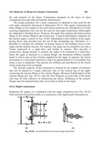
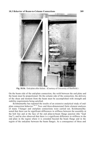
This document provides an overview and guide to design criteria for bolted and riveted joints. It contains information on types of structural fasteners, general provisions for design, behavior of individual rivets and bolts, installation of high-strength bolts, and design of various joint configurations like symmetric butt splices. The guide is intended to be a comprehensive resource on bolted and riveted joints, explaining their behavior under different loads and providing both allowable stress and load factor design recommendations.


