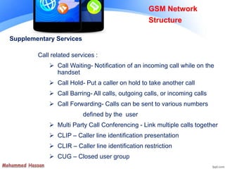
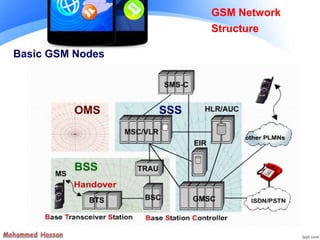
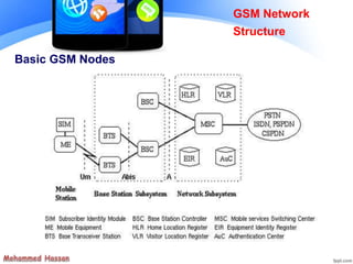
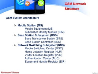
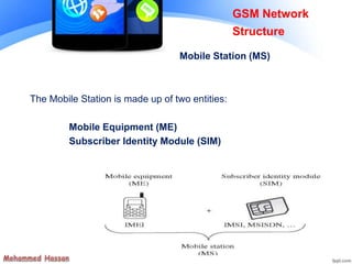
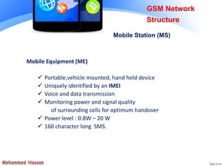
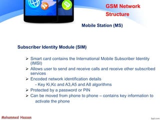
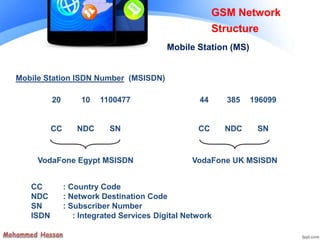
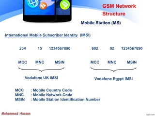
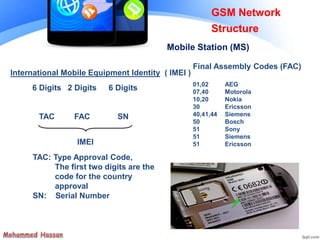
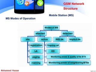
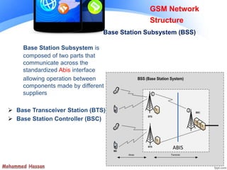
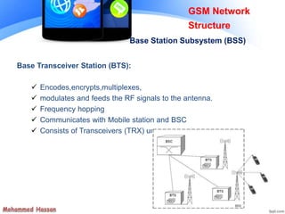
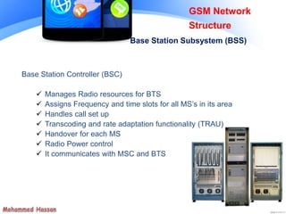
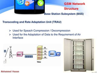
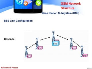
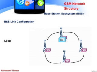
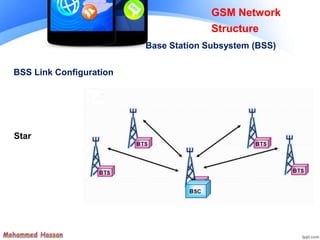
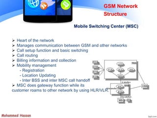
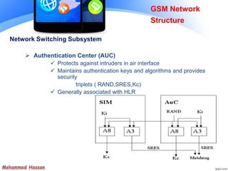
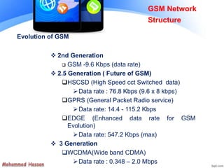
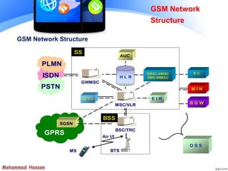
GSM
Global System for Mobile
Communication
By: Mohammed Hassan
E-mail:
GSM Network
Structure
Chapter Objectives
By the End of this Chapter you will :
 Know the role of the Basic nodes that compose the GSM
network
 Know how they are interconnected together
 Know the different Identities used in GSM World
GSM Services
 Tele-services
 Bearer or Data Services
 Supplementary services
GSM Network
Structure
Tele Services
 Telecommunication services
that enable voice communication via mobile phones
 Offered services
- Mobile telephony
- Emergency calling
GSM Network
Structure
Bearer Services
 Include various data services for information transfer between GSM
and other networks like PSTN, ISDN etc at rates from 300 to 9600
bps
 Short Message Service (SMS)
 up to 160 character alphanumeric data transmission to/from the
mobile terminal
 Unified Messaging Services(UMS)
 Voice mailbox
 E-mail
GSM Network
Structure
Supplementary Services
Call related services :
 Call Waiting- Notification of an incoming call while on the
handset
 Call Hold- Put a caller on hold to take another call
 Call Barring- All calls, outgoing calls, or incoming calls
 Call Forwarding- Calls can be sent to various numbers
defined by the user
 Multi Party Call Conferencing - Link multiple calls together
 CLIP – Caller line identification presentation
 CLIR – Caller line identification restriction
 CUG – Closed user group
GSM Network
Structure
Basic GSM Nodes
GSM Network
Structure
Basic GSM Nodes
GSM Network
Structure
GSM System Architecture
 Mobile Station (MS)
Mobile Equipment (ME)
Subscriber Identity Module (SIM)
 Base Station Subsystem (BSS)
Base Transceiver Station (BTS)
Base Station Controller (BSC)
 Network Switching Subsystem(NSS)
Mobile Switching Center (MSC)
Home Location Register (HLR)
Visitor Location Register (VLR)
Authentication Center (AUC)
Equipment Identity Register (EIR)
GSM Network
Structure
The Mobile Station is made up of two entities:
Mobile Equipment (ME)
Subscriber Identity Module (SIM)
GSM Network
Structure
Mobile Station (MS)
Mobile Equipment (ME)
 Portable,vehicle mounted, hand held device
 Uniquely identified by an IMEI
 Voice and data transmission
 Monitoring power and signal quality
of surrounding cells for optimum handover
 Power level : 0.8W – 20 W
 160 character long SMS.
GSM Network
Structure
Mobile Station (MS)
Subscriber Identity Module (SIM)
 Smart card contains the International Mobile Subscriber Identity
(IMSI)
 Allows user to send and receive calls and receive other subscribed
services
 Encoded network identification details
- Key Ki,Kc and A3,A5 and A8 algorithms
 Protected by a password or PIN
 Can be moved from phone to phone – contains key information to
activate the phone
GSM Network
Structure
Mobile Station (MS)
CC : Country Code
NDC : Network Destination Code
SN : Subscriber Number
ISDN : Integrated Services Digital Network
VodaFone Egypt MSISDN
20
CC
10
NDC
1100477
SN
Mobile Station ISDN Number (MSISDN)
VodaFone UK MSISDN
44
CC
385
NDC
196099
SN
GSM Network
Structure
Mobile Station (MS)
International Mobile Subscriber Identity (IMSI)
MCC : Mobile Country Code
MNC : Mobile Network Code
MSIN : Mobile Station Identification Number
Vodafone UK IMSI
234
MCC
15
MNC
1234567890
MSIN
Vodafone Egypt IMSI
602
MCC
02
MNC
1234567890
MSIN
GSM Network
Structure
Mobile Station (MS)
International Mobile Equipment Identity ( IMEI )
IMEI
6 Digits
TAC
2 Digits
FAC
6 Digits
SN
TAC: Type Approval Code,
The first two digits are the
code for the country
approval
SN: Serial Number
Final Assembly Codes (FAC)
01,02 AEG
07,40 Motorola
10,20 Nokia
30 Ericsson
40,41,44 Siemens
50 Bosch
51 Sony
51 Siemens
51 Ericsson
GSM Network
Structure
Mobile Station (MS)
MS Modes of Operation
GSM Network
Structure
Mobile Station (MS)
Base Station Subsystem is
composed of two parts that
communicate across the
standardized Abis interface
allowing operation between
components made by different
suppliers
 Base Transceiver Station (BTS)
 Base Station Controller (BSC)
GSM Network
Structure
Base Station Subsystem (BSS)
ABIS
Base Transceiver Station (BTS):
 Encodes,encrypts,multiplexes,
 modulates and feeds the RF signals to the antenna.
 Frequency hopping
 Communicates with Mobile station and BSC
 Consists of Transceivers (TRX) units
GSM Network
Structure
Base Station Subsystem (BSS)
GSM Network
Structure
Base Station Subsystem (BSS)
BTS is usually composed of:
 Transceiver (TRX)
 It basically does transmission and
reception of signals.
 Power amplifier (PA)
 Amplifies the signal from for transmission
through antenna
 Combiner
 Combines feeds so that they could be
sent out through a single antenna.
 Allows for a reduction in the number of
antenna used.
GSM Network
Structure
Base Station Subsystem (BSS)
 Multiplexer
 separating sending and receiving signals to/from antenna
 Alarm extension system
 Collects working status alarms of various units in the BTS and
extends them to operations and maintenance (O&M)
monitoring stations.
 Control function
 Controls and manages the various units of BTS, including any
software. On-the-spot configurations, status changes,
software upgrades
 Baseband receiver unit (BBxx)
 Frequency hopping, signal DSP
 Antenna
GSM Network
Structure
Base Station Subsystem (BSS)
Base Transceiver Station (BTS):
Base Station Subsystem (BSS)
Base Station Controller (BSC)
 Manages Radio resources for BTS
 Assigns Frequency and time slots for all MS’s in its area
 Handles call set up
 Transcoding and rate adaptation functionality (TRAU)
 Handover for each MS
 Radio Power control
 It communicates with MSC and BTS
GSM Network
Structure
Transcoding and Rate Adaptation Unit (TRAU)
 Used for Speach Compression / Decompression
 Used for the Adaptation of Data to the Requirement of Air
Interface
GSM Network
Structure
Base Station Subsystem (BSS)
GSM Network
Structure
Base Station Subsystem (BSS)
BSS Link Configuration
Cascade
GSM Network
Structure
Base Station Subsystem (BSS)
BSS Link Configuration
Loop
GSM Network
Structure
Base Station Subsystem (BSS)
BSS Link Configuration
Star
Mobile Switching Center (MSC)
GSM Network
Structure
 Heart of the network
 Manages communication between GSM and other networks
 Call setup function and basic switching
 Call routing
 Billing information and collection
 Mobility management
- Registration
- Location Updating
- Inter BSS and inter MSC call handoff
 MSC does gateway function while its
customer roams to other network by using HLR/VLR.
GSM Network
Structure
Mobile Switching Center (MSC)
Network Switching Subsystem
 Home Location Registers (HLR)
permanent database about mobile subscribers in a large service
area (generally one per GSM network operator) database
contains IMSI,MSISDN,prepaid/postpaid,roaming
restrictions,supplementary services.
GSM Network
Structure
Network Switching Subsystem
 Visitor Location Registers (VLR)
 Temporary database which updates whenever new MS enters
its area, by HLR database
 Controls those mobiles roaming in its area
 Reduces number of queries to HLR
 Database contains IMSI,TMSI,MSISDN,MSRN,Location
Area,authentication key
GSM Network
Structure
Network Switching Subsystem
 Authentication Center (AUC)
 Protects against intruders in air interface
 Maintains authentication keys and algorithms and provides
security
triplets ( RAND,SRES,Kc)
 Generally associated with HLR
GSM Network
Structure
Network Switching Subsystem
 Equipment Identity Register (EIR)
 Database that is used to track handsets using the
IMEI
(International Mobile Equipment Identity)
 Made up of three sub-classes:
The White List, The Black List and the Gray List
 Only one EIR per PLMN
GSM Network
Structure
GSM Specifications
GSM 900
Mobile to BTS (uplink): 890-915 Mhz
BTS to Mobile(downlink):935-960 Mhz
Bandwidth : 2* 25 Mhz
GSM 1800
Mobile to BTS (uplink): 1710-1785 Mhz
BTS to Mobile(downlink) 1805-1880 Mhz
Bandwidth : 2* 75 Mhz
GSM Network
Structure
GSM Specification
 Carrier Separation : 200 Khz
 Duplex Distance : 45 Mhz
 No. of RF carriers : 124
 Access Method : TDMA/FDMA
 Modulation Method : GMSK
 Modulation data rate : 270.833 Kbps
GSM Network
Structure
Characteristics of GSM Standard
 Fully digital system using 900,1800 MHz frequency band.
 TDMA over radio carriers(200 KHz carrier spacing).
 8 full rate or 16 half rate TDMA channels per carrier.
 User/terminal authentication for fraud control.
 Encryption of speech and data transmission over the radio path.
 Full international roaming capability.
 Low speed data services (up to 9.6 Kb/s).
 Compatibility with ISDN.
 Support of Short Message Service (SMS).
GSM Network
Structure
Evolution of GSM
 2nd Generation
 GSM -9.6 Kbps (data rate)
 2.5 Generation ( Future of GSM)
HSCSD (High Speed cct Switched data)
Data rate : 76.8 Kbps (9.6 x 8 kbps)
GPRS (General Packet Radio service)
Data rate: 14.4 - 115.2 Kbps
EDGE (Enhanced data rate for GSM
Evolution)
Data rate: 547.2 Kbps (max)
 3 Generation
WCDMA(Wide band CDMA)
Data rate : 0.348 – 2.0 Mbps
GSM Network
Structure
SSSS
D T I
BTSBTS
O S S
ISDN
PLMN
PSTN
ISDNISDN
PLMNPLMN
PSTN M I N
S C
B G W
H L R
AUC
SMSC-GMSC
SMS-IWMSC
E I R
GWMSCGWMSC
MSC/VLRMSC/VLR
MSMS
Air I/f
GPRS
SGSN
BSC/TRCBSC/TRC
BSSBSS
GSM Network Structure
GSM Network
Structure

Gsm (2)

  • 1.
    GSM Global System forMobile Communication By: Mohammed Hassan E-mail:
  • 2.
    GSM Network Structure Chapter Objectives Bythe End of this Chapter you will :  Know the role of the Basic nodes that compose the GSM network  Know how they are interconnected together  Know the different Identities used in GSM World
  • 3.
    GSM Services  Tele-services Bearer or Data Services  Supplementary services GSM Network Structure
  • 4.
    Tele Services  Telecommunicationservices that enable voice communication via mobile phones  Offered services - Mobile telephony - Emergency calling GSM Network Structure
  • 5.
    Bearer Services  Includevarious data services for information transfer between GSM and other networks like PSTN, ISDN etc at rates from 300 to 9600 bps  Short Message Service (SMS)  up to 160 character alphanumeric data transmission to/from the mobile terminal  Unified Messaging Services(UMS)  Voice mailbox  E-mail GSM Network Structure
  • 6.
    Supplementary Services Call relatedservices :  Call Waiting- Notification of an incoming call while on the handset  Call Hold- Put a caller on hold to take another call  Call Barring- All calls, outgoing calls, or incoming calls  Call Forwarding- Calls can be sent to various numbers defined by the user  Multi Party Call Conferencing - Link multiple calls together  CLIP – Caller line identification presentation  CLIR – Caller line identification restriction  CUG – Closed user group GSM Network Structure
  • 7.
    Basic GSM Nodes GSMNetwork Structure
  • 8.
    Basic GSM Nodes GSMNetwork Structure
  • 9.
    GSM System Architecture Mobile Station (MS) Mobile Equipment (ME) Subscriber Identity Module (SIM)  Base Station Subsystem (BSS) Base Transceiver Station (BTS) Base Station Controller (BSC)  Network Switching Subsystem(NSS) Mobile Switching Center (MSC) Home Location Register (HLR) Visitor Location Register (VLR) Authentication Center (AUC) Equipment Identity Register (EIR) GSM Network Structure
  • 10.
    The Mobile Stationis made up of two entities: Mobile Equipment (ME) Subscriber Identity Module (SIM) GSM Network Structure Mobile Station (MS)
  • 11.
    Mobile Equipment (ME) Portable,vehicle mounted, hand held device  Uniquely identified by an IMEI  Voice and data transmission  Monitoring power and signal quality of surrounding cells for optimum handover  Power level : 0.8W – 20 W  160 character long SMS. GSM Network Structure Mobile Station (MS)
  • 12.
    Subscriber Identity Module(SIM)  Smart card contains the International Mobile Subscriber Identity (IMSI)  Allows user to send and receive calls and receive other subscribed services  Encoded network identification details - Key Ki,Kc and A3,A5 and A8 algorithms  Protected by a password or PIN  Can be moved from phone to phone – contains key information to activate the phone GSM Network Structure Mobile Station (MS)
  • 13.
    CC : CountryCode NDC : Network Destination Code SN : Subscriber Number ISDN : Integrated Services Digital Network VodaFone Egypt MSISDN 20 CC 10 NDC 1100477 SN Mobile Station ISDN Number (MSISDN) VodaFone UK MSISDN 44 CC 385 NDC 196099 SN GSM Network Structure Mobile Station (MS)
  • 14.
    International Mobile SubscriberIdentity (IMSI) MCC : Mobile Country Code MNC : Mobile Network Code MSIN : Mobile Station Identification Number Vodafone UK IMSI 234 MCC 15 MNC 1234567890 MSIN Vodafone Egypt IMSI 602 MCC 02 MNC 1234567890 MSIN GSM Network Structure Mobile Station (MS)
  • 15.
    International Mobile EquipmentIdentity ( IMEI ) IMEI 6 Digits TAC 2 Digits FAC 6 Digits SN TAC: Type Approval Code, The first two digits are the code for the country approval SN: Serial Number Final Assembly Codes (FAC) 01,02 AEG 07,40 Motorola 10,20 Nokia 30 Ericsson 40,41,44 Siemens 50 Bosch 51 Sony 51 Siemens 51 Ericsson GSM Network Structure Mobile Station (MS)
  • 16.
    MS Modes ofOperation GSM Network Structure Mobile Station (MS)
  • 17.
    Base Station Subsystemis composed of two parts that communicate across the standardized Abis interface allowing operation between components made by different suppliers  Base Transceiver Station (BTS)  Base Station Controller (BSC) GSM Network Structure Base Station Subsystem (BSS) ABIS
  • 18.
    Base Transceiver Station(BTS):  Encodes,encrypts,multiplexes,  modulates and feeds the RF signals to the antenna.  Frequency hopping  Communicates with Mobile station and BSC  Consists of Transceivers (TRX) units GSM Network Structure Base Station Subsystem (BSS)
  • 19.
    GSM Network Structure Base StationSubsystem (BSS) BTS is usually composed of:  Transceiver (TRX)  It basically does transmission and reception of signals.  Power amplifier (PA)  Amplifies the signal from for transmission through antenna  Combiner  Combines feeds so that they could be sent out through a single antenna.  Allows for a reduction in the number of antenna used.
  • 20.
    GSM Network Structure Base StationSubsystem (BSS)  Multiplexer  separating sending and receiving signals to/from antenna  Alarm extension system  Collects working status alarms of various units in the BTS and extends them to operations and maintenance (O&M) monitoring stations.  Control function  Controls and manages the various units of BTS, including any software. On-the-spot configurations, status changes, software upgrades  Baseband receiver unit (BBxx)  Frequency hopping, signal DSP  Antenna
  • 21.
    GSM Network Structure Base StationSubsystem (BSS) Base Transceiver Station (BTS):
  • 22.
    Base Station Subsystem(BSS) Base Station Controller (BSC)  Manages Radio resources for BTS  Assigns Frequency and time slots for all MS’s in its area  Handles call set up  Transcoding and rate adaptation functionality (TRAU)  Handover for each MS  Radio Power control  It communicates with MSC and BTS GSM Network Structure
  • 23.
    Transcoding and RateAdaptation Unit (TRAU)  Used for Speach Compression / Decompression  Used for the Adaptation of Data to the Requirement of Air Interface GSM Network Structure Base Station Subsystem (BSS)
  • 24.
    GSM Network Structure Base StationSubsystem (BSS) BSS Link Configuration Cascade
  • 25.
    GSM Network Structure Base StationSubsystem (BSS) BSS Link Configuration Loop
  • 26.
    GSM Network Structure Base StationSubsystem (BSS) BSS Link Configuration Star
  • 27.
    Mobile Switching Center(MSC) GSM Network Structure
  • 28.
     Heart ofthe network  Manages communication between GSM and other networks  Call setup function and basic switching  Call routing  Billing information and collection  Mobility management - Registration - Location Updating - Inter BSS and inter MSC call handoff  MSC does gateway function while its customer roams to other network by using HLR/VLR. GSM Network Structure Mobile Switching Center (MSC)
  • 29.
    Network Switching Subsystem Home Location Registers (HLR) permanent database about mobile subscribers in a large service area (generally one per GSM network operator) database contains IMSI,MSISDN,prepaid/postpaid,roaming restrictions,supplementary services. GSM Network Structure
  • 30.
    Network Switching Subsystem Visitor Location Registers (VLR)  Temporary database which updates whenever new MS enters its area, by HLR database  Controls those mobiles roaming in its area  Reduces number of queries to HLR  Database contains IMSI,TMSI,MSISDN,MSRN,Location Area,authentication key GSM Network Structure
  • 31.
    Network Switching Subsystem Authentication Center (AUC)  Protects against intruders in air interface  Maintains authentication keys and algorithms and provides security triplets ( RAND,SRES,Kc)  Generally associated with HLR GSM Network Structure
  • 32.
    Network Switching Subsystem Equipment Identity Register (EIR)  Database that is used to track handsets using the IMEI (International Mobile Equipment Identity)  Made up of three sub-classes: The White List, The Black List and the Gray List  Only one EIR per PLMN GSM Network Structure
  • 33.
    GSM Specifications GSM 900 Mobileto BTS (uplink): 890-915 Mhz BTS to Mobile(downlink):935-960 Mhz Bandwidth : 2* 25 Mhz GSM 1800 Mobile to BTS (uplink): 1710-1785 Mhz BTS to Mobile(downlink) 1805-1880 Mhz Bandwidth : 2* 75 Mhz GSM Network Structure
  • 34.
    GSM Specification  CarrierSeparation : 200 Khz  Duplex Distance : 45 Mhz  No. of RF carriers : 124  Access Method : TDMA/FDMA  Modulation Method : GMSK  Modulation data rate : 270.833 Kbps GSM Network Structure
  • 35.
    Characteristics of GSMStandard  Fully digital system using 900,1800 MHz frequency band.  TDMA over radio carriers(200 KHz carrier spacing).  8 full rate or 16 half rate TDMA channels per carrier.  User/terminal authentication for fraud control.  Encryption of speech and data transmission over the radio path.  Full international roaming capability.  Low speed data services (up to 9.6 Kb/s).  Compatibility with ISDN.  Support of Short Message Service (SMS). GSM Network Structure
  • 36.
    Evolution of GSM 2nd Generation  GSM -9.6 Kbps (data rate)  2.5 Generation ( Future of GSM) HSCSD (High Speed cct Switched data) Data rate : 76.8 Kbps (9.6 x 8 kbps) GPRS (General Packet Radio service) Data rate: 14.4 - 115.2 Kbps EDGE (Enhanced data rate for GSM Evolution) Data rate: 547.2 Kbps (max)  3 Generation WCDMA(Wide band CDMA) Data rate : 0.348 – 2.0 Mbps GSM Network Structure
  • 37.
    SSSS D T I BTSBTS OS S ISDN PLMN PSTN ISDNISDN PLMNPLMN PSTN M I N S C B G W H L R AUC SMSC-GMSC SMS-IWMSC E I R GWMSCGWMSC MSC/VLRMSC/VLR MSMS Air I/f GPRS SGSN BSC/TRCBSC/TRC BSSBSS GSM Network Structure GSM Network Structure