Downloaded 13 times


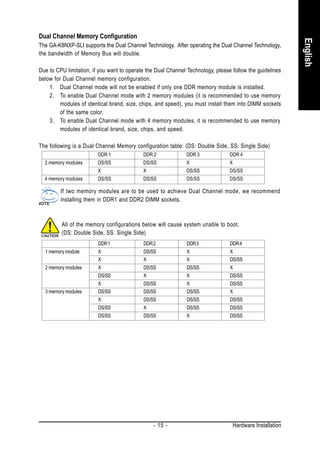


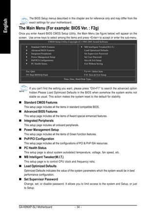

![2-1 Standard CMOS Features
English
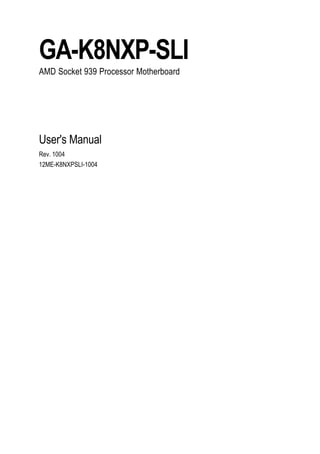
CMOS Setup Utility-Copyright (C) 1984-2005 Award Software
Standard CMOS Features
Date (mm:dd:yy) Thu, Jun 17 2004 Item Help
Time (hh:mm:ss) 22:31:24 Menu Level
IDE Channel 0 Master [None] Change the day, month,
IDE Channel 0 Slave [None] year
IDE Channel 1 Master [None]
IDE Channel 1 Slave [None] <Week>
Sun. to Sat.
Drive A [1.44M, 3.5"] <Month>
Floppy 3 Mode Support [Disabled] Jan. to Dec.
Halt On [All, But Keyboard] <Day>
1 to 31 (or maximum
allowed in the month)
<Year>
1999 to 2098
: Move Enter: Select +/-/PU/PD: Value F10: Save ESC: Exit F1: General Help
F5: Previous Values F7: Optimized Defaults
Date
The date format is <week>, <month>, <day>, <year>.
Week The week, from Sun to Sat, determined by the BIOS and is display only
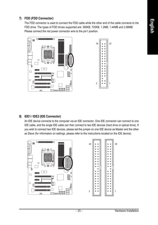
Month The month, Jan. Through Dec.
Day The day, from 1 to 31 (or the maximum allowed in the month)
Year The year, from 1999 through 2098
Time
The times format in <hour> <minute> <second>. The time is calculated based on the 24-hour
military-time clock. For example, 1 p.m. is 13:00:00.
IDE Channel 0 Master/Slave; IDE Channel 1 Master/Slave
IDE HDD Auto-Detection Press "Enter" to select this option for automatic device detection.
IDE Channel 0 Master/Slave; IDE Channel 1 Master/Slave devices setup. You can use one of
three methods:
Auto Allows BIOS to automatically detect IDE devices during POST. (Default
value)
None Select this if no IDE devices are used and the system will skip the automatic
detection step and allow for faster system start up.
Manual User can manually input the correct settings.
Access Mode Use this to set the access mode for the hard drive. The four options are:
CHS/LBA/Large/Auto(default:Auto)
Capacity Capacity of currently installed hard drive.
Hard drive information should be labeled on the outside drive casing. Enter the appropriate option
based on this information.
Cylinder Number of cylinders
Head Number of heads
Precomp Write precomp
Landing Zone Landing zone
GA-K8NXP-SLI Motherboard - 36 -](https://image.slidesharecdn.com/motherboardmanualk8nxpslie-111209150410-phpapp01/85/GIGABYTE-GA-K8NXP-SLI-AMD-Socket-939-Processor-Motherboard-36-320.jpg)
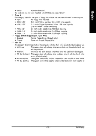
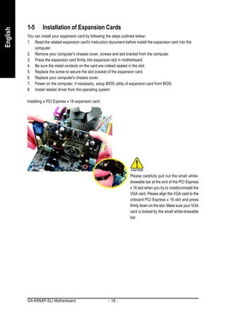
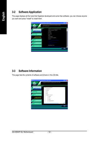
![2-2 Advanced BIOS Features
English
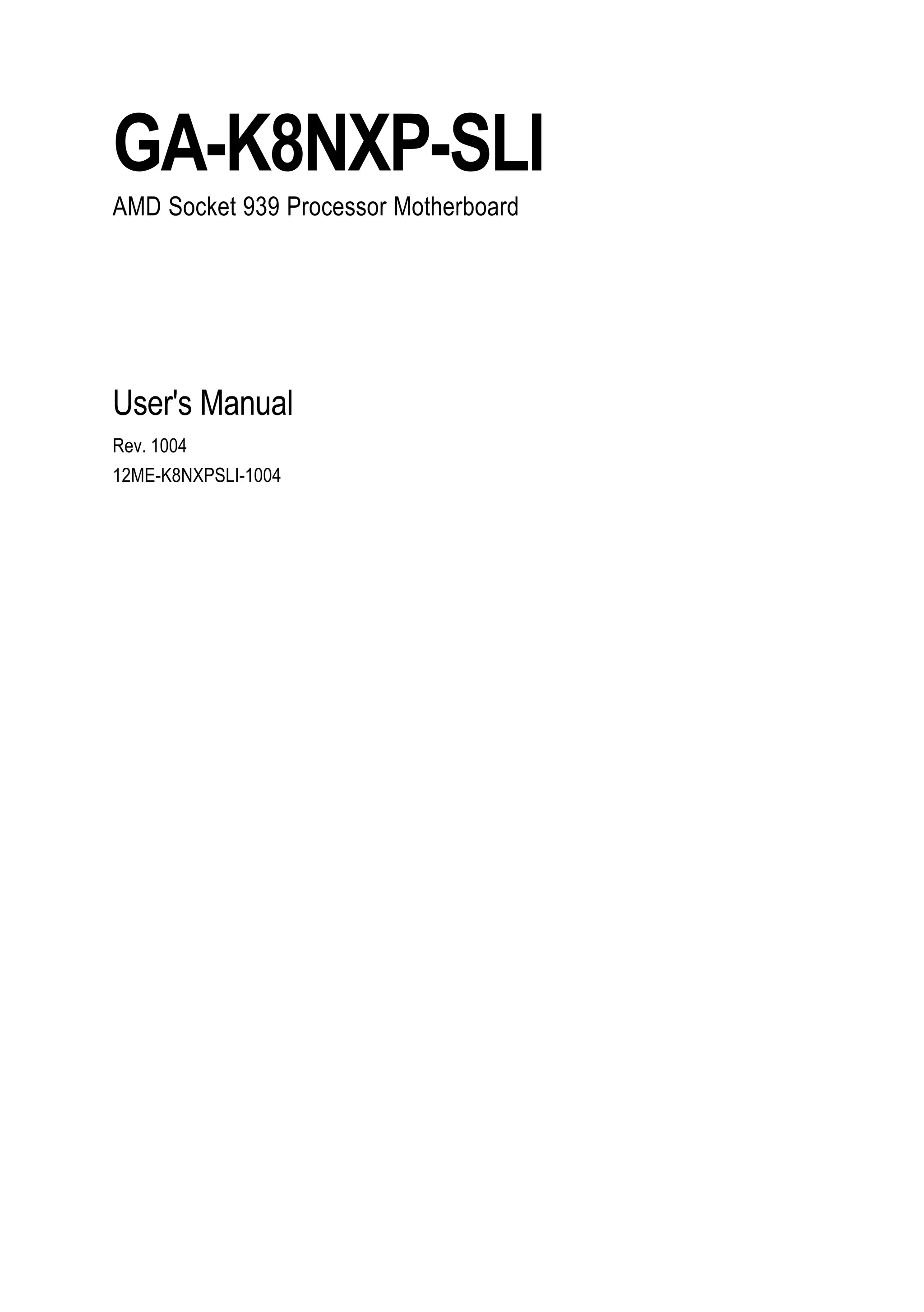
CMOS Setup Utility-Copyright (C) 1984-2005 Award Software
Advanced BIOS Features
Hard Disk Boot Priority [Press Enter] Item Help
First Boot Device [Floppy] Menu Level
Second Boot Device [Hard Disk]
Third Boot Device [CDROM] Select Hard Disk Boot
Boot Up Floppy Seek [Disabled] Device Priority
Password Check [Setup]
Init Display First [PEG]
: Move Enter: Select +/-/PU/PD: Value F10: Save ESC: Exit F1: General Help
F5: Previous Values F7: Optimized Defaults
Hard Disk Boot Priority
Select boot sequence for onboard(or add-on cards) SCSI, RAID, etc.
Use < > or < > to select a device, then press<+> to move it up, or <-> to move it down the list. Press
<ESC> to exit this menu.
First / Second / Third Boot Device
Floppy Select your boot device priority by Floppy.
LS120 Select your boot device priority by LS120.
Hard Disk Select your boot device priority by Hard Disk.
CDROM Select your boot device priority by CDROM.
ZIP Select your boot device priority by ZIP.
USB-FDD Select your boot device priority by USB-FDD.
USB-ZIP Select your boot device priority by USB-ZIP.
USB-CDROM Select your boot device priority by USB-CDROM.
USB-HDD Select your boot device priority by USB-HDD.
Legacy LAN Select your boot device priority by LAN.
Disabled Select your boot device priority by Disabled.
Boot Up Floppy Seek
During POST, BIOS will determine the floppy disk drive installed is 40 or 80 tracks. 360K type is 40
tracks 720K, 1.2M and 1.44M are all 80 tracks.
Enabled BIOS searches for floppy disk drive to determine it is 40 or 80 tracks. Note that BIOS
can not tell from 720K, 1.2M or 1.44M drive type as they are all 80 tracks.
Disabled BIOS will not search for the type of floppy disk drive by track number. Note that
there will not be any warning message if the drive installed is 360K. (Default
value)
GA-K8NXP-SLI Motherboard - 38 -](https://image.slidesharecdn.com/motherboardmanualk8nxpslie-111209150410-phpapp01/85/GIGABYTE-GA-K8NXP-SLI-AMD-Socket-939-Processor-Motherboard-38-320.jpg)

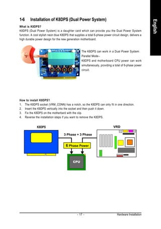
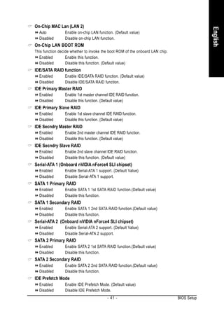
![2-3 Integrated Peripherals
English
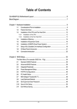
CMOS Setup Utility-Copyright (C) 1984-2005 Award Software
Integrated Peripherals
On-Chip IDE Channel0 [Enabled] Item Help
On-Chip IDE Channel1 [Enabled] Menu Level
IDE DMA transfer access [Enabled]
On-Chip MAC Lan [Auto]
On-Chip LAN BOOT ROM [Disabled]
IDE/SATA RAID function [Enabled]
IDE Primary Master RAID [Disabled]
IDE Primary Slave RAID [Disabled]
IDE Secndry Master RAID [Disabled]
IDE Secndry Slave RAID [Disabled]
Serial-ATA 1 [Enabled]
SATA 1 Primary RAID [Enabled]
SATA 1 Secondary RAID [Enabled]
Serial-ATA 2 [Enabled]
SATA 2 Primary RAID [Enabled]
SATA 2 Secondary RAID [Enabled]
IDE Prefetch Mode [Enabled]
On-Chip USB [V1.1+V2.0]
USB Memory Type [SHADOW]
: Move Enter: Select +/-/PU/PD: Value F10: Save ESC: Exit F1: General Help
F5: Previous Values F7: Optimized Defaults
CMOS Setup Utility-Copyright (C) 1984-2005 Award Software
Integrated Peripherals
USB Keyboard Support [Disabled] Item Help
USB Mouse Support [Disabled] Menu Level
AC97 Audio [Auto]
Onboard 1394 [Enabled]
Onboard LAN control [Enabled]
Onboard LAN Boot ROM [Disabled]
SATA RAID-5 Function [Enabled]
Onboard Serial Port 1 [3F8/IRQ4]
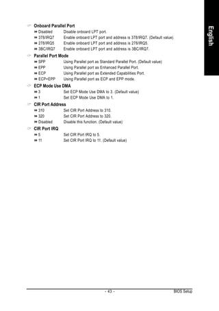
Onboard Parallel Port [378/IRQ7]
Parallel Port Mode [SPP]
x ECP Mode Use DMA 3
CIR Port Address [Disabled]
x CIR Port IRQ 11
: Move Enter: Select +/-/PU/PD: Value F10: Save ESC: Exit F1: General Help
F5: Previous Values F7: Optimized Defaults
On-Chip IDE Channel0
Enabled Enable onboard 1st channel IDE port. (Default value)
Disabled Disable onboard 1st channel IDE port.
On-Chip IDE Channel1
Enabled Enable onboard 2nd channel IDE port. (Default value)
Disabled Disable onboard 2nd channel IDE port.
IDE DMA transfer access
Enabled Enable IDE DMA transfer access. (Default Value)
Disabled Disable IDE DMA transfer access.
GA-K8NXP-SLI Motherboard - 40 -](https://image.slidesharecdn.com/motherboardmanualk8nxpslie-111209150410-phpapp01/85/GIGABYTE-GA-K8NXP-SLI-AMD-Socket-939-Processor-Motherboard-40-320.jpg)
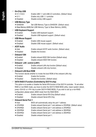
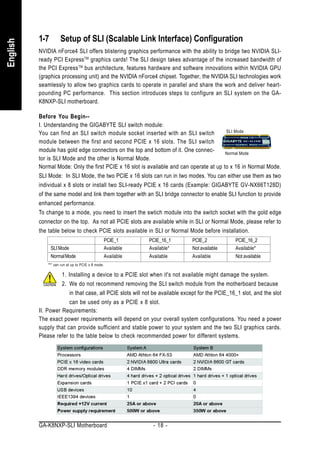
![2-4 Power Management Setup
English
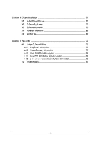
CMOS Setup Utility-Copyright (C) 1984-2005 Award Software
Power Management Setup
ACPI Suspend Type [S1(POS)] Item Help
Soft-Off by Power button [Instant-Off] Menu Level
PME Event Wake Up [Disabled]
Modem Ring On [Disabled]
USB Resume from Suspend [Disabled]
Power-On by Alarm [Disabled]
x Day of Month Alarm Everyday
x Time (hh:mm:ss) Alarm 0:0:0
Power On By Mouse [Disabled]
Power On By Keyboard [Disabled]
AC BACK Function [Soft-Off]
: Move Enter: Select +/-/PU/PD: Value F10: Save ESC: Exit F1: General Help
F5: Previous Values F7: Optimized Defaults
ACPI Suspend Type
S1(POS) Set ACPI suspend type to S1/POS(Power On Suspend). (Default value)
S3(STR) Set ACPI suspend type to S3/STR(Suspend To RAM).
Soft-Off by Power button
Instant-Off Press power button then Power off instantly. (Default value)
Delay 4 Sec. Press power button 4 sec. to Power off. Enter suspend if button is pressed
less than 4 sec.
PME Event Wake Up
This feature requires an ATX power supply that provides at least 1A on the 5VSB lead.
Disabled Disable this function.(Default value)
Enabled Enable PME as wake up event.
Modem Ring On
An incoming call via modem can awake the system from any suspend state.
Disabled Disable this function. (Default value)
Enabled Enable Modem Ring On function.
USB Resume from Suspend
Disabled Disable this function. (Default value)
Enable Enable USB device wake up system from suspend mode.
Power-On by Alarm
You can set "Power-On by Alarm" item to enabled and key in Date/Time to power on system.
Disabled Disable this function. (Default value)
Enabled Enable alarm function to POWER ON system.
If Power-On by Alarm is Enabled.
Day of Month Alarm : Everyday, 1~31
Time (hh: mm: ss) Alarm : (0~23) : (0~59) : (0~59)
GA-K8NXP-SLI Motherboard - 44 -](https://image.slidesharecdn.com/motherboardmanualk8nxpslie-111209150410-phpapp01/85/GIGABYTE-GA-K8NXP-SLI-AMD-Socket-939-Processor-Motherboard-44-320.jpg)

![2-5 PnP/PCI Configurations
English
CMOS Setup Utility-Copyright (C) 1984-2005 Award Software
PnP/PCI Configurations
PCI 1 IRQ Assignment [Auto] Item Help
PCI 2 IRQ Assignment [Auto] Menu Level
On-board Device IRQ Assign [Auto]
Device(s) using this
INT:
Display Cntrlr
-Bus 5 Dev 0 Func 0
: Move Enter: Select +/-/PU/PD: Value F10: Save ESC: Exit F1: General Help
F5: Previous Values F7: Optimized Defaults
PCI 1 IRQ Assignment
Auto Auto assign IRQ to PCI 1. (Default value)
3,4,5,7,9,10,11,12,14,15 Set IRQ 3,4,5,7,9,10,11,12,14,15 to PCI 1.
PCI 2 IRQ Assignment
Auto Auto assign IRQ to PCI 2. (Default value)
3,4,5,7,9,10,11,12,14,15 Set IRQ 3,4,5,7,9,10,11,12,14,15 to PCI 2.
On-board Device IRQ Assign
Auto Auto assign IRQ to onboard device. (Default value)
3,4,5,7,9,10,11,12,14,15 Set IRQ 3,4,5,7,9,10,11,12,14,15 to onboard device.
GA-K8NXP-SLI Motherboard - 46 -](https://image.slidesharecdn.com/motherboardmanualk8nxpslie-111209150410-phpapp01/85/GIGABYTE-GA-K8NXP-SLI-AMD-Socket-939-Processor-Motherboard-46-320.jpg)
![2-6 PC Health Status
English
CMOS Setup Utility-Copyright (C) 1984-2005 Award Software
PC Health Status
Vcore 1.550V Item Help
DDR25V 2.624V Menu Level
+3.3V 3.360V
+12V 11.795V [Disabled]
Current CPU Temperature 38 oC Don't monitor
Current CPU FAN Speed 3245 RPM current temperature
Current POWER FAN Speed 0 RPM
Current SYSTEM FAN Speed 0 RPM [60 oC-90oC]
CPU Warning Temperature [Disabled] Alarm when current
CPU FAN Fail Warning [Disabled] temperature over than
CPU Smart FAN Control [Enabled] the selected
temperature
: Move Enter: Select +/-/PU/PD: Value F10: Save ESC: Exit F1: General Help
F5: Previous Values F7: Optimized Defaults
Current Voltage(V) Vcore / DDR25V / +3.3V / +12V
Detect system's voltage status automatically.
Current CPU Temperature
Detect CPU temperature automatically.
Current CPU/POWER/SYSTEM FAN Speed (RPM)
Detect CPU/Power/System fan speed status automatically.
CPU Warning Temperature
60 o C / 140 o F Monitor CPU temperature at 60o C / 140oF.
70 o C / 158 o F Monitor CPU temperature at 70o C / 158oF.
80 o C / 176 o F Monitor CPU temperature at 80o C / 176oF.
90 o C / 194 o F Monitor CPU temperature at 90o C / 194oF.
Disabled Disable this function. (Default value)
CPU FAN Fail Warning
Disabled Disable CPU fan fail warning function. (Default value)
Enabled Enable CPU fan fail warning function.
CPU Smart FAN Control
Disabled Disable this function.
Enabled When this function is enabled, CPU fan will run at different speed depending
on CPU temperature. Users can adjust the fan speed with Easy Tune
based on their requirements. (Default value)
- 47 - BIOS Setup](https://image.slidesharecdn.com/motherboardmanualk8nxpslie-111209150410-phpapp01/85/GIGABYTE-GA-K8NXP-SLI-AMD-Socket-939-Processor-Motherboard-47-320.jpg)
![2-7 MB Intelligent Tweaker(M.I.T.)
English
CMOS Setup Utility-Copyright (C) 1984-2005 Award Software
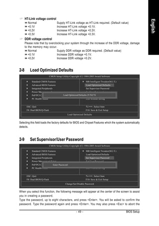
MB Intelligent Tweaker(M.I.T.)
CPU Frequency [200.0] Item Help
CPU Spread Spectrum [Center Spread] Menu Level
PCIE Clock [100Mhz]
K8 CPU Clock Ratio [Default]
Robust Graphics Booster [Auto]
CPU Voltage Control [Normal]
Normal CPU Vcore 1.500V
Core Power voltage control [Normal]
HT-Link voltage control [Normal]
DDR voltage control [Normal]
: Move Enter: Select +/-/PU/PD: Value F10: Save ESC: Exit F1: General Help
F5: Previous Values F7: Optimized Defaults
Incorrect using these features may cause your system broken. For power end-user use only.
CPU Frequency
200.0~400.0MHz Set CPU Frequency from 200MHz to 400MHz.
CPU Spread Spectrum
Disabled Disable CPU Spread Spectrum.
Center Spread Set CPU Spread Spectrum to Center Spread. (Default value)
PCIE Clock
100~150MHz Set PCIE Clock from 100MHz to 150MHz.
K8 CPU Clock Ratio
This setup option will automatically assign by CPU detection. The option will display "Locked" and
read only or will not show up if the CPU ratio is not changeable.
Robust Graphics Booster
Select the options can enhance the VGA graphics card bandwidth to get higher performance.
Auto Set Robust Graphics Booster to Auto. (Default value)
Fast Set Robust Graphics Booster to Fast.
Turbo Set Robust Graphics Booster to Turbo.
CPU Voltage Control
Supports adjustable CPU Vcore from 0.800V to 1.750V by 0.025V step. (Default value: Normal)
Warning: CPU may be damaged or CPU life-cycle may be reduced when CPU is over-voltage.
Normal CPU Vcore
Display your CPU normal voltage.
Core Power voltage control
Normal Set core power voltage as required. (Default value)
+0.1v Increase core power voltage +0.1V.
+0.2v Increase core power voltage +0.2V.
+0.3v Increase core power voltage +0.3V.
GA-K8NXP-SLI Motherboard - 48 -](https://image.slidesharecdn.com/motherboardmanualk8nxpslie-111209150410-phpapp01/85/GIGABYTE-GA-K8NXP-SLI-AMD-Socket-939-Processor-Motherboard-48-320.jpg)
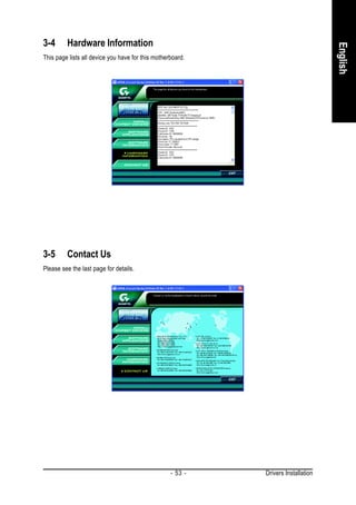


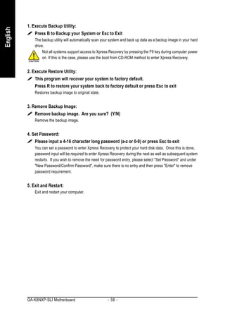

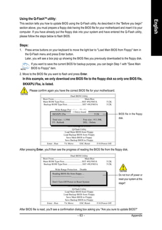
![3. Press Y button on your keyboard after you are sure to update BIOS.
English
Then it will begin to update BIOS. The progress of updating BIOS will be displayed.
Please do not take out the floppy disk when it begins flashing BIOS.
4. Press any keys to return to the Q-Flash menu when the BIOS updating procedure is completed.
Dual BIOS Utility
Boot From......................................... Main Bios
Main ROM Type/Size.............................SST 49LF003A 512K
Backup ROM Type/Size.........................SST 49LF003A 512K
Wide Range Protection Disable
Boot From Main Bios
You can repeat Step 1 to
Auto Recovery Enable
!! Copy BIOS completed - Pass !! 4 to flash the backup
Halt On Error Disable
Copy Main ROM Data to continue
BIOS, too.
Please press any key to Backup
Load Default Settings
Save Settings to CMOS
Q-Flash Utility
Load Main BIOS from Floppy
Load Backup BIOS from Floppy
Save Main BIOS to Floppy
Save Backup BIOS to Floppy
Enter : Run :Move ESC:Reset F10:Power Off
5. Press Esc and then Y button to exit the Q-Flash utility. The computer will restart automatically after
you exit Q-Flash.
Dual BIOS Utility
Boot From......................................... Main Bios
Main ROM Type/Size.............................SST 49LF003A 512K
Backup ROM Type/Size.........................SST 49LF003A 512K
Wide Range Protection Disable
Boot From Main Bios
Auto Recovery Enable
Are you sure to RESET ?
Halt On Error Disable
Copy Main ROM Data to Backup
[Enter] to continure or [Esc] to abort...
Load Default Settings
Save Settings to CMOS
Q-Flash Utility
Load Main BIOS from Floppy
Load Backup BIOS from Floppy
Save Main BIOS to Floppy
Save Backup BIOS to Floppy
Enter : Run :Move ESC:Reset F10:Power Off
After system reboots, you may find the BIOS version on your boot screen becomes the one you flashed.
Award Modular BIOS v6.00PG, An Energy Star Ally
Copyright (C) 1984-2003, Award Software, Inc.
The BIOS file Intel i875P AGPset BIOS for 8KNXP Ultra Fba
Check System Health OK , VCore = 1.5250
becomes Fba after Main Processor : Intel Pentium(R) 4 1.6GHz (133x12)
<CPUID : 0F27 Patch ID : 0027>
updating. Memory Testing : 131072K OK
Memory Frequency 266 MHz in Single Channel
Primary Master : FUJITSU MPE3170AT ED-03-08
Primary Slave : None
Secondary Master : CREATIVEDVD-RM DVD1242E BC101
Secondary Slave : None
Press DEL to enter SETUP / Dual BIOS / Q-Flash / F9 For Xpress Recovery
09/23/2003-i875P-6A79BG03C-00
GA-K8NXP-SLI Motherboard - 64 -](https://image.slidesharecdn.com/motherboardmanualk8nxpslie-111209150410-phpapp01/85/GIGABYTE-GA-K8NXP-SLI-AMD-Socket-939-Processor-Motherboard-64-320.jpg)
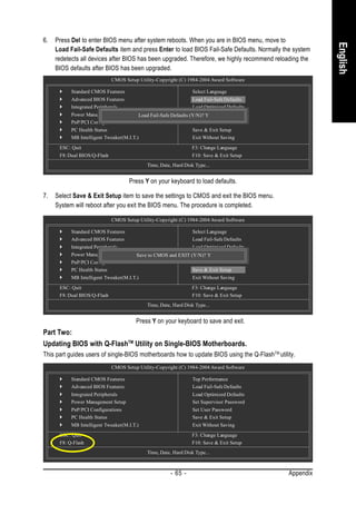
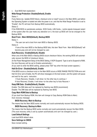
![3. Press Y button on your keyboard after you are sure to update BIOS.
English
Then it will begin to update BIOS. The progress of updating BIOS will be shown at the same time.
Q-Flash Utility V1.30
Flash Type/Size.................................SST 49LF003A 256K
Keep DMI Data BIOS Now
Updating Enable Do not trun off power or
Update BIOS from Floppy
>>>>>>>>>>>>>>>>>>>.........................
Save BIOS to Floppy reset your system
Enter : Run :Move ESC:Reset
Don't Turn Off Power or Reset System F10:Power Off at this stage!!
4. Press any keys to return to the Q-Flash menu when the BIOS updating procedure is completed.
Q-Flash Utility V1.30
Flash Type/Size.................................SST 49LF003A 256K
Keep DMI Data Enable
!! Copy BIOS completed - Pass !!
Update BIOS from Floppy
Save BIOS to Floppy
Please press any key to continue
Enter : Run :Move ESC:Reset F10:Power Off
5. Press Esc and then Y button to exit the Q-Flash utility. The computer will restart automatically after
you exit Q-Flash.
Q-Flash Utility V1.30
Flash Type/Size.................................SST 49LF003A 256K
Keep DMI Data Enable
Are you sure to RESET ?
Update BIOS from Floppy
Save BIOS to Floppy
[Enter] to continure or [Esc] to abort...
Enter : Run :Move ESC:Reset F10:Power Off
After system reboots, you may find the BIOS version on your boot screen becomes the one you flashed.
Award Modular BIOS v6.00PG, An Energy Star Ally
Copyright (C) 1984-2003, Award Software, Inc.
The BIOS file Intel 845GE AGPSet BIOS for 8GE800 F4
Check System Health OK
becomes F4 after Main Processor : Intel Pentium(R) 4 1.7GHz (100x17.0)
<CPUID : 0F0A Patch ID : 0009>
updating Memory Testing : 122880K OK + 8192K Shared Memory
Primary Master : FUJITSU MPE3170AT ED-03-08
Primary Slave : None
Secondary Master : CREATIVEDVD-RM DVD1242E BC101
Secondary Slave : None
Press DEL to enter SETUP / Q-Flash
03/18/2003-I845GE-6A69YG01C-00
6. Press Del to enter BIOS menu after system reboots and "Load BIOS Fail-Safe Defaults". See how
to Load BIOS Fail-Safe Defaults, please kindly refer to Step 6 to 7 in Part One.
Congratulation!! You have updated BIOS successfully!!
- 67 - Appendix](https://image.slidesharecdn.com/motherboardmanualk8nxpslie-111209150410-phpapp01/85/GIGABYTE-GA-K8NXP-SLI-AMD-Socket-939-Processor-Motherboard-67-320.jpg)

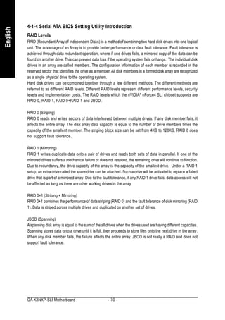
![Please follow the steps below to construct a complete RAID array:
English
1) Have ready your hard drives for RAID construction.
Note: To achieve best performance, it is recommended that the hard drives used are of similar make
and storage capacity.
2) Please attach the hard drive connectors to their appropriate location on the motherboard ie. IDE, SCSI,
or SATA.
3) Enter the motherboard BIOS and locate RAID setup (Please refer to the section on Integrated Peripherals).
4) Enter RAID setup in the BIOS and select the RAID type (For instance, enter F10 to select NVIDIA RAID;
Ctrl + S to select Silicon Image).
5) Complete driver installation.
6) Complete RAID utility installation.
More information on steps 4 and 5 is provided. (For more detailed setup information, please visit "Support
Motherboard Technology Guide section" on our website at http:www.gigabyte.com.tw to read or download
the information you need.)
Configuring the Nvidia RAID BIOS
The NVRAID BIOS setup lets you choose the RAID array type and which hard drives you want to make part
of the array.
Entering the RAID BIOS Setup
1. After rebooting your computer, wait until you see the RAID software prompting you to press F10. The
RAID prompt appears as part of the system POST and boot process prior to loading the OS. You have a few
seconds to press F10 before the window disappears.
NVIDIA RAID IDE ROM BIOS 4.76
Copyright (C) 2004 NVIDIA Corp.
Detecting array ...
Press F10 to enter RAID setup utility ...
Press F10.
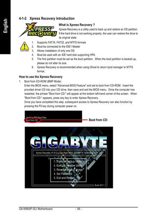
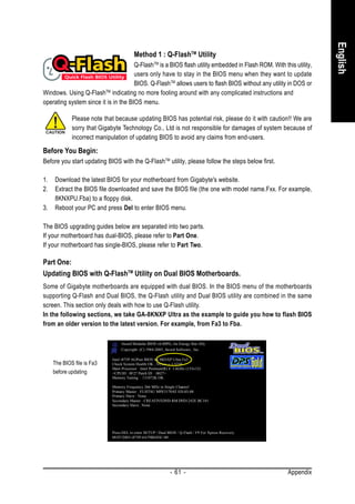
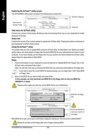
The NVIDIA RAID Utility - Define a New Array window appears (as Figure below).
NVIDIA RAID Utility Nov 5 2004
- Define a New Array -
RAID Mode: Mirroring Striping Block: Optimal
Free Disks Array Disks
Loc Disk Model Name Loc Disk Model Name
2.0.M ST3120026AS
2.1.M ST3120026AS [ ] Add
[ ] Del
[ESC] Quit [F6] Back [F7] Finish [TAB] Navigate [ ] Select [ENTER] Popup
- 71 - Appendix](https://image.slidesharecdn.com/motherboardmanualk8nxpslie-111209150410-phpapp01/85/GIGABYTE-GA-K8NXP-SLI-AMD-Socket-939-Processor-Motherboard-71-320.jpg)
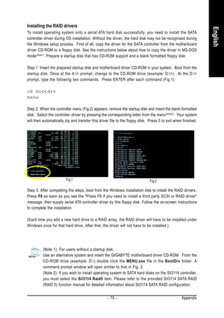
![Using the "Define a New Array" Window
English
If necessary, press the tab key to move from field to field until the appropriate field is highlighted.
Selecting the RAID Mode
By default, this is set to Mirroring. To change to a different RAID mode, press the down arrow key until the
mode that you want appears in the RAID Mode box - either Mirroring, Striping, Spanning, or Stripe Mirroring.
Selecting the Striping Block Size
Striping block size is given in kilobytes, and affects how data is arranged on the disk. It is recommended to
leave this value at the default Optimal, which is 64KB, but the values can be between 4 KB and 128 KB.
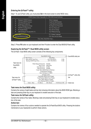
Assigning the Disks
The disks that you enabled from the RAID Config BIOS setup page appear in the Free Disks block. These
are the drives that are available for use as RAID array disks. To designate a free disk to be used as a RAID
array disk,
1. Tab to the Free Disks section. The first disk in the list is selected.
2. Move it from the Free Disks block to the Array Disks block by pressing the right arrow key ( ). The
first disk in the list is moved, and the next disk in the list is selected and ready to be moved.
3. Continue pressing the right-arrow key ( ) until all the disks that you want to use as RAID array disks
appear in the Array Disks block.
NVIDIA RAID Utility Nov 5 2004
- Define a New Array -
RAID Mode: Mirroring Striping Block: Optimal
Free Disks Array Disks
Loc Disk Model Name Loc Disk Model Name
2.0.M ST3120026AS
[ ] Add 2.1.M ST3120026AS
[ ] Del
[ESC] Quit [F6] Back [F7] Finish [TAB] Navigate [ ] Select [ENTER] Popup
GA-K8NXP-SLI Motherboard - 72 -](https://image.slidesharecdn.com/motherboardmanualk8nxpslie-111209150410-phpapp01/85/GIGABYTE-GA-K8NXP-SLI-AMD-Socket-939-Processor-Motherboard-72-320.jpg)
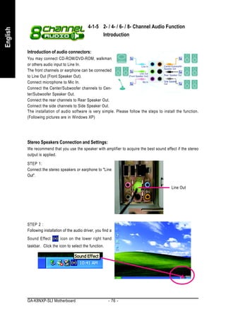
![Completing the RAID BIOS Setup
English
After assigning your RAID array disks, press F7. The Clear disk data prompt appears.
NVIDIA RAID Utility Nov 5 10 2004
- Define a New Array -
RAID Mode: Mirroring Striping Block: Optimal
Free Disks Clear disk data ? Disks
Array
Loc Disk Model Name Loc Disk Model Name
1.0.M ST3120026AS
[Y] YES [N] NO
1.1.M ST3120026AS
[ ] Add
[ ] Del
[ESC] Quit [F6] Back [F7] Finish [TAB] Navigate [ ] Select [ENTER] Popup
Press Y if you want to wipe out all the data from the RAID array, otherwise press N. You must choose Yes if
the drives were previously used as RAID drives. The Array List window appears, where you can review the
RAID arrays that you have set up.
You can select a disk array as boot device if you want to boot operating system from an array. Use the arrow
keys to select the array, then press B to specify the array as bootable.
NVIDIA RAID Utility Nov 5 2004
- Array List -
Boot Id Status Vendor Array Model Name
No 2 Healthy NVIDIA MIRROR 111.79G
[Ctrl-X] Exit [ ] Select [B] Set Boot [N] New Array [ENTER] Detail
- 73 - Appendix](https://image.slidesharecdn.com/motherboardmanualk8nxpslie-111209150410-phpapp01/85/GIGABYTE-GA-K8NXP-SLI-AMD-Socket-939-Processor-Motherboard-73-320.jpg)
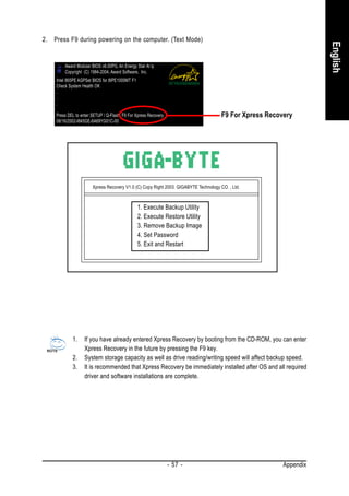
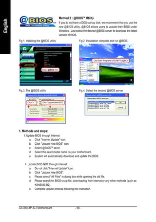
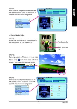
![Press Enter to view and verify details. The Array Detail screen appears.
English
The Array Detail screen shows various information about the array that you selected, such as Striping Block
used, RAID Mode, Striping Width, Disk Model Name, and disk capacity.
Array 2 : NVIDIA MIRROR 111.79G
- Array Detail -
RAID Mode: Mirroring
Striping Width : 1 Striping Block: 64K
Adapt Channel M/S Index Disk Model Name Capacity
2 0 Master 0 ST3120026AS 111.79GB
2 1 Master 1 ST3120026AS 111.79GB
[R] Rebuild [D] Delete [C] Clear Disk [ENTER] Return
If you want to mark this disk as empty and wipe out all its contents, press C.
At the prompt, press Y to wipe out all the data, otherwise press N.
Press Enter again to go back to the previous screen and then press Ctrl + X to exit the RAID setup.
Now that the RAID setup has been configured from the RAID BIOS, the next step is to configure and load
drivers under Windows.
GA-K8NXP-SLI Motherboard - 74 -](https://image.slidesharecdn.com/motherboardmanualk8nxpslie-111209150410-phpapp01/85/GIGABYTE-GA-K8NXP-SLI-AMD-Socket-939-Processor-Motherboard-74-320.jpg)
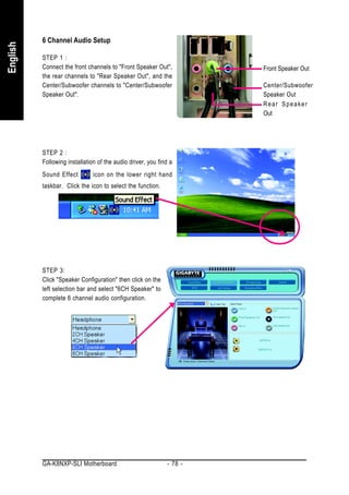


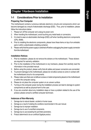
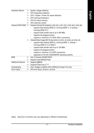
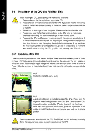
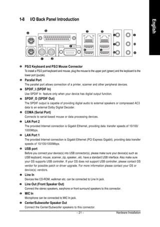
1. Move the socket lever to the unlocked position and align the CPU pins with the socket. 2. Lower the CPU gently into the socket without forcing it. 3. Apply thermal paste to the surface of the CPU and install the fan heat sink components. 4. Connect the fan heat sink power connector to the CPU_FAN connector on the motherboard.


