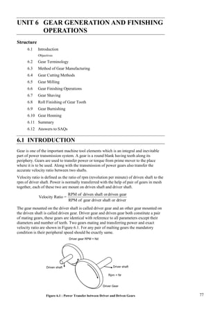
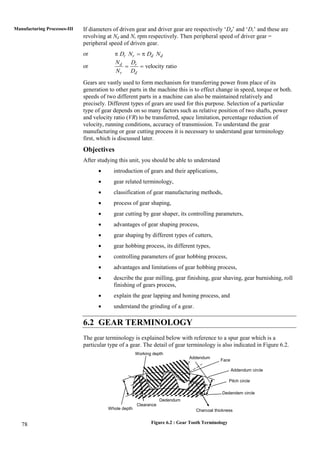
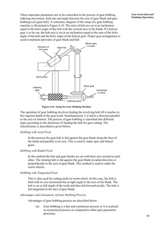
77
Gear Generation and
Finishing Operations
UNIT 6 GEAR GENERATION AND FINISHING
OPERATIONS
Structure
6.1 Introduction
Objectives
6.2 Gear Terminology
6.3 Method of Gear Manufacturing
6.4 Gear Cutting Methods
6.5 Gear Milling
6.6 Gear Finishing Operations
6.7 Gear Shaving
6.8 Roll Finishing of Gear Tooth
6.9 Gear Burnishing
6.10 Gear Honning
6.11 Summary
6.12 Answers to SAQs
6.1 INTRODUCTION
Gear is one of the important machine tool elements which is an integral and inevitable
part of power transmission system. A gear is a round blank having teeth along its
periphery. Gears are used to transfer power or torque from prime mover to the place
where it is to be used. Along with the transmission of power gears also transfer the
accurate velocity ratio between two shafts.
Velocity ratio is defined as the ratio of rpm (revolution per minute) of driven shaft to the
rpm of driver shaft. Power is normally transferred with the help of pair of gears in mesh
together, each of these two are mount on driven shaft and driver shaft.
RPM of driven shaft ordriven gear
Velocity Ratio =
RPM of gear driver shaft or driver
The gear mounted on the driver shaft is called driver gear and an other gear mounted on
the driven shaft is called driven gear. Driver gear and driven gear both constitute a pair
of mating gears, these gears are identical with reference to all parameters except their
diameters and number of teeth. Two gears mating and transferring power and exact
velocity ratio are shown in Figure 6.1. For any pair of malting gears the mandatory
condition is their peripheral speed should be exactly same.
Figure 6.1 : Power Transfer between Driver and Driven Gears
Driven shaft
Driver Gear
Driver shaft
Rpm = Nr
Driver gear RPM = Nd
78
Manufacturing Processes-III If diameters of driven gear and driver gear are respectively ‘Dd’ and ‘Dr’ and these are
revolving at Nd and Nr rpm respectively. Then peripheral speed of driver gear =
peripheral speed of driven gear.
or r r d d
D N D N
  
or velocity ratio
d r
r d
N D
N D
 
Gears are vastly used to form mechanism for transferring power from place of its
generation to other parts in the machine this is to effect change in speed, torque or both.
speeds of two different parts in a machine can also be maintained relatively and
precisely. Different types of gears are used for this purpose. Selection of a particular
type of gear depends on so many factors such as relative position of two shafts, power
and velocity ratio (VR) to be transferred, space limitation, percentage reduction of
velocity, running conditions, accuracy of transmission. To understand the gear
manufacturing or gear cutting process it is necessary to understand gear terminology
first, which is discussed later.
Objectives
After studying this unit, you should be able to understand
 introduction of gears and their applications,
 gear related terminology,
 classification of gear manufacturing methods,
 process of gear shaping,
 gear cutting by gear shaper, its controlling parameters,
 advantages of gear shaping process,
 gear shaping by different types of cutters,
 gear hobbing process, its different types,
 controlling parameters of gear hobbing process,
 advantages and limitations of gear hobbing process,
 describe the gear milling, gear finishing, gear shaving, gear burnishing, roll
finishing of gears process,
 explain the gear lapping and honing process, and
 understand the grinding of a gear.
6.2 GEAR TERMINOLOGY
The gear terminology is explained below with reference to a spur gear which is a
particular type of a gear. The detail of gear terminology is also indicated in Figure 6.2.
Figure 6.2 : Gear Tooth Terminology
Working depth
Addendum
Dedendum
Clearance
Whole depth
Addendum circle
Pitch circle
Dedendem circle
Face
Charcoal thickness
79
Gear Generation and
Finishing Operations
Gear Blank
The metallic workpiece accurately sized and shaped which is used as workpiece
for gear cutting is called gear blank. The diameter of gear blank is called gear
blank diameter.
Addendum Circle
It is an imaginary circle which passes through top of all gear teeth and represents
maximum diameter of a gear. This maximum diameter is equal to gear blank
diameter.
Addendum
Addendum of a gear is the radial distance between addendum circle and pitch
circle of the gear.
Pitch Circle
This is an imaginary circle along which thickness of a gear tooth becomes equal to
spacing between them.
Deddndum
It is the radial distance between pitch circle and root circle of a gear.
Root Circle
Root circle is an imaginary circle which is supposes to pass through root of all
gear teeth.
Tooth Clearance
This is the distance between the top of a tooth of one gear and the bottom of the
corresponding tooth of other mating gear is known as clearance or tooth clearance.
Pressure Angle
The angle made by the line of action with the common tangent to the pitch circle
is called pressure angle.
Face
It is the portion of the tooth lying between top of the tooth and pitch circle.
Flank
This is portion of the gear tooth between its pitch circle and root circle.
Thickness of a Gear Tooth
It is also called chorodal thickness of gear tooth. It is width of two gear tooth
measured along the pitch circle. At the pitch circle width of gear tooth becomes
equal to the width of spacing between two consecutive gear teeth.
Backlash
It is difference between actual tooth thickness and the width of space at which it
meshes with other gear.
Circular Pitch
It is the distance between corresponding points of adjacent teeth measured along
the pitch circle.
Diametral Pitch
It is number of teeth of a gear per unit of pitch circle diameter.
Diametal pitch ( )
N
p
d

where ‘N’ is the number of teeth ‘d’ is the pitch circle diameter.
80
Manufacturing Processes-III Module
It is reciprocal of diameteral pitch. It is linear distance in mm that each tooth of
the gear would occupy if the gear teeth were spaced along the pitch diameter.
d
m
N

with usual notations; m is module of gear.
6.3 METHOD OF GEAR MANUFACTURING
In broader sense the gears can be manufactured by the following three methods.
(a) Casting
For casting of gears sand moulds or permanent moulds are prepared, then molten
metal is poured into the mold cavity to get the required gear. Cast iron gears are
made by this method comfortably. These gears (casted gears) cannot be very fine,
these are rough, low strength, and with some inaccuracies in operation. There cost
of production is very low. This method is recommended for manufacturing of
large sized gears where cost and power transmission are important than operating
accuracy and noise level.
(b) Plastic Moulding
Plastic mould is also one of the way of gear manufacturing. In plastic moulding
gears of plastic material can be manufactured by using injection moulding or
compression moulding. These are the very light duties gears used for transmission
of very low amount of power but maintains velocity ratio accurately.
Plastic moulding is also used for making gears of metal. In this process the
metallic workpiece is heated first to bring it to a plastic state and then it is
moulded to the required shape with the help of mechanical tools, die, and
application of pressure. This process is used to make light duty smaller gears with
accuracy. Non-ferrous metals can also be used as raw material for gear making by
plastic moulding methods.
(c) Machining
This is most widely used gear manufacturing method. Gear blank of accurate size
and shape is first prepared by cutting it from metal stock. The gear blank can also
be the metal casting. This method lies under the category of chip forming process.
Gear is prepared by cutting one by one tooth in the gear blank of desired shape
and size along it periphery. Different gear cutting methods are used in this
category. These methods are described in details.
6.3.1 Gears Shaping
Gear shaping is one of the gear generating methods. In this process gear tooth are
accurately sized and shaped by cutting them by a multipoint cutting tool. Various gear
shaping processes are listed and then described below :
(a) Gear cutting by gear shaper.
(b) Rack planning process.
(c) Hobbing process.
Gear Cutting by Gear Shaper
This process uses a pinion shaped cutter carrying clearance on the tooth face and
sides and a hole at its centre for mounting it on a stub arbor or spindle of the
machine. The cutter is mounted by keeping its axis in vertical position. It is also
made reciprocating along the vertical axis up and down with adjustable and
81
Gear Generation and
Finishing Operations
predecide amplitude. The cutter and the gear blank both are set to rotate at very
low rpm about their respective axis. The relative rpm of both (cutter and blank)
can be fixed to any of the available value with the help of a gear train. This way
all the cutting teeth of cutter come is action one-by-one giving sufficient time for
their cooling and incorporating a longer tool life. The specific advantages of the
process over other processes, its product cycle time is very low and negligible
dimensional variability from one unit to other in case of mass production. The
principle of gear cutting by this process as explained above is depicted in the
Figure 6.3. The main parameters to be controlled in the process are described
below.
Figure 6.3 : Process of Gear Cutting by Shaper Cutter
Cutting Speed
Shaper cutter can move vertically upward and downward during the
operation. The downward during the operation. The downward movement
of the cutter is the cutting stroke and its speed (linear) with which it comes
down is the cutting speed. After the completion of cutting stroke, cutter
comes back to its top position which is called return stroke. There is no
cutting in the return stroke. Length of cutting stroke can be adjusted to any
value out of available values on the machine.
Indexing Motion
Indexing motion is equivalent to feed motion in the gear shaping operation.
Slow rotations of the gear cutter and workpiece provide the circular feed to
the operation. These two rpms are adjusted with the help of a change gear
mechanism. The rpm are relatively adjusted such that each rotation of the
cutter the gear blank revolves through
n
N
revolution.
where n  Number of teeth of cutter, and
N = Number of teeth to be cut on the blank.
Depth of Cut
Indexing movement or circular feed and reciprocating motions continue
until the required numbers of teeth to the required depth are made all along
the periphery of the gear blank. The required depth is maintained gradually
by cutting the teeth into two or three pass. In each successive pass, the depth
of cut is increased as compared to its previous path. This gradual increase in
depth of cut takes place by increasing the value of linear feed in return
stroke.
The whole of this process is carried out an a gear shaping machine which is
of the shape of a column and knee type milling machine. All the motions
Gear Blank
Feed
Cutter
spindle
Stroke motion
Rotary gear
shaper cutter
Work spindle
82
Manufacturing Processes-III given to gear blank and gear cutter are set controlled very precisely. A setup
of gear shaping machine is shown in Figure 6.4.
Figure 6.4 : Setup for Gear Shaping Machine
Advantages of Gear Shaping Process
Main advantages of gear shaping process are described below :
(a) Shorter product cycle time and suitable for making medium
and large sized gears in mass production.
(b) Different types of gears can be made except worm and worm
wheels.
(c) Close tolerance in gear cutting can be maintained.
(d) Accuracy and repeatability of gear tooth profile can be
maintained comfortably.
(e) For same value of gear tooth module a single type of cutter can
be used irrespective of number of teeth in the gear.
Limitations
Main limitations of gear shaping process are described below :
(a) It cannot be used to make worm and work wheel which is a
particular type of gear.
(b) There is no cutting in the return stroke of the gear cutter, so
there is a need to make return stroke faster than the cutting
stroke.
(c) In case of cutting of helical gears, a specially designed guide
containing a particular helix and helix angle, corresponding to
the teeth to be made, is always needed on urgent basis.
Gear Shaping by Rack Shaped Cutter
In this method, gear cutting is done by a rack shaped cutter called rack type
cutter. The principle is illustrated in Figure 6.5. The working is similar to
shaping process done by gear type cutter.
The process involves rotation (low rpm) of the gear blank as the rack type
cutter reciprocates along a vertical line. Cutting is done only in the
downward stroke, the upward stroke is only a return movement. The main
difference of this method with the previous one is that once the full length
of the rack is utilized the gear cutting of operation is stopped to bring the
gear blank to its starting position so that another pass of gear cutting can be
Top
Spindle head
Cutter spindle
Cutter
Work spindle
Gear blank
Work table
Guide
Column
Change
gear
train
83
Gear Generation and
Finishing Operations
started. So this operation is intermittent for cutting larger gears having large
number of teeth over their periphery.
Figure 6.5 : Gear Cutting by Rack Shaped Cutter
Another popular method of gear chopping is Rack Planning Process which
is described below.
Rack Planning Process
This process is used for shaping of spur and helical gear teeth with the help of a
rack type cutter. In this process the gear blank is mounted on a horizontal aims and
rotated impertinently. At the same time the gear blank is kept in mesh with a
reciprocating rack type cutter. The process is shown in Figure 6.6. The teeth cutter
gradually removes material to cut the teeth and to make the required profile. The
whole operation includes some important operations. These are feeding cutter into
the blank, rolling the blank intermittently and keeping cutter in mesh with the
rolling gear blank. After each mesh the gear blank is rolled by an amount equal to
one pitch of gear tooth. After each cutting, the rack is withdrawn and re-meshed
after the rotation of gear blank.
Figure 6.6 : Gear Shaping by Rack Type Cutter
A few of the initial teeth of rack type cutter perform the cutting action and
remaining teeth to very small removal of workpiece material, these are used to
maintain dimensional accuracy of the already cut teeth and to provide them a good
finishing.
The basic principle of gear shaping is same but by slight altering the process some
more different methods of gear shaping are discussed below.
Sunderland Process
This process is named after the name of its inventor. In this process the
cutter reciprocates in a direction towards and away from the gear blank. The
process is illustrated in Figure 6.7. Cutter is gradually fed into the gear
blank to the required depth. As soon as cutting is completed upto the
desired depth, the blank rotates through one pitch distance. The cutter also
moves along with the blank and then suddenly withdraws, stepped back by
an amount equal to one pitch distance and again made to reciprocate in the
normal way. The gear blank does not move till the completion of whole
cutting upto the required depth. The whole motion and movement control is
basically maintained with the help of synchronous motor and gear train.
Gear blank
Work spindle
Rack type cutter
Length of rack
Reciprocating
movements
Rotation
Rack type cutter
Reciprocation
Revolution
Rear blank
84
Manufacturing Processes-III
Figure 6.7 : Process of Sunderland Gear Shaping Process
Mang Process
In this process gear blank is mounted on the machine table, keeping its axis
in a vertical position. The cutter head, carrying rack type cutter, slides
vertically in the sides provided at the front of the machine. The cutter can be
set at any angle in a vertical plane. The cutter can also be made
reciprocating in any direction. The rest of the process re-samples with other
gear shaping processes.
Gear Hobbing Process
In addition to the gear shaping process another process used for gear generation is
gear hobbing. In this process, the gear blank is rolled with a rotating cutter called
hob. Gear hobbing is done by using a multipoint cutting tool called gear hob. It
looks like a worm gear having a number of straight flutes all around its periphery
parallel to its axis. These flutes are so shaped by giving proper angles to them so
that these work as cutting edges. In gear hobbing operation, the hob is rotated at a
suitable rpm and simultaneously fed to the gear blank. The gear blank is alos kept
as revolving. Rpm of both, gear blank and gear hob are so synchronized that for
each revolution of gear bob the gear blank rotates by a distance equal to one pitch
distance of the gear to be cut. Motion of both gear blank and hob are maintained
continuously and steady. A gear hob is shown in Figure 6.8 and the process of
gear hobbing is illustrated in Figure 6.9. The hob teeth behave like screw threads,
having a definite helix angle. During operation the hob is tilted to helix angle so
that its cutting edges remain square with the gear blank. Gear hobbing is used for
making a wide variety of gears like spur gear, helical, hearing-bone, splines and
gear sprockets, etc.
Figure 6.8 : Gear Hob
Figure 6.9 : Process of Gear Hobbing
Gear blank
Direction of Rotation
Reciprocating
motion
Cutter
Motion to cutter offer
each withdrawal
Cutting
Teeth
Straight
flutes
(gashes)
Hob
Feed
Axis of
Rotation
Gear
blank
85
Gear Generation and
Finishing Operations
Three important parameters are to be controlled in the process of gear hobbing
indexing movement, feed rate and angle between the axis of gear blank and gear
hobbing tool (gear hob). A schematic diagram of the setup of a gear hobbing
machine is illustrated in Figure 6.10. The aims of hob are set at an inclination
equal to the helix angle of the hob with the vertical axis of the blank. If a helical
gear is to be cut, the hob axis is set at an inclination equal to the sum of the helix
angle of the hob and the helix angle of the helical gear. Proper gear arrangement is
used to maintain rpm ratio of gear blank and hob.
Figure 6.10 : Setup for Gear Hobbing Machine
The operation of gear hobbing involves feeding the revolving hob till it reaches to
the required depth of the gear tooth. Simultaneously it is fed in a direction parallel
to the axis of rotation. The process of gear hobbing is classified into different
types according to the directions of feeding the hob for gear cutting. The
classification is described as given below.
Hobbing with Axial Feed
In this process the gear hob is fed against the gear blank along the face of
the blank and parallel to its axis. This is used to make spur and helical
gears.
Hobbing with Radial Feed
In this method the hob and gear blanks are set with their axis normal to each
other. The rotating hob is fed against the gear blank in radial direction or
perpendicular to the axis of gear blank. This method is used to make the
worm wheels.
Hobbing with Tangential Feed
This is also used for cutting teeth on worm wheel. In this case, the hob is
held with its axis horizontal but at right angle to the axis of the blank. The
hob is set at full depth of the tooth and then fed forward axially. The hob is
fed tangential to the face of gear blank.
Advantages and Limitations of Gear Hobbing Process
Advantages of gear hobbing process are described below :
(a) Gear hobbing is a fast and continuous process so it is realized
as economical process as compared to other gear generation
processes.
Gear hob
Direction of
hob reed
Work piece
Bevel rears
in mesh
Bevel gear
Connected
to drive
Indexing
gear
Indexing warm
86
Manufacturing Processes-III (b) Lower production cycle time, i.e. faster production rate.
(c) The process has a larger variability’s in the following of sense
as compared to other gear machining processes.
(i) Capable to make wide variety of gears like spur gear,
helical gears, worms, splines, sprockets, etc.
(ii) Process of required indexing (named so) is quite
simplified and capable to make any number of teeth with
consistent accuracy of module.
(iii) A special type of gear named harringbon gear cam be
generated by gear hobbing exclusively.
(iv) Wide variety of batch size (small to large volume) can be
accommodated by this process.
(d) Several gear blanks, mounted on the same arbor, can be
processed simultaneously.
(e) Hob is multipoint cutting tool having multi cutting teeth or
edges at a time few number of cutting edges work so lots of
time is available to dissipate the generated heat. There is no
over heating and cutting tool.
In addition to above mentioned large number of advantages there is one
glaring limitation of the process of gear hobbing. That is manufacturing of
internal gears is not possible.
6.5 GEAR MILLING
The gear milling operation is used for gear cutting. All types of gears can be made by
using gear milling. Milling cutter is selected specifically for a particular type of gear and
module. The periphery of the gear blank is divided into required number of equi-spaced
parts. The required number of parts should be equal to the number teeth to be made on
the gear blank. The method of dividing the periphery is called indexing which is an
integral part of the operation of gear milling. The details of the operation of gear milling
and indexing are explained in Unit 1 of this course.
Gear milling is a slower process of gear generation as compared to other gear generation
process. In this process gear is generated by cutting one-by-one tooth. Gears are to be
made, it is not suitable for larger batch size. The other methods required very high
capital cost and setup cost as compared to gear milling so these are not economical for
smaller batch size, only gear cutting by milling operation is recommended for smaller
batch size.
6.6 GEAR FINISHING OPERATIONS
Surface of gear teeth produced by any of the generating process is not accurate and of
good quality (smooth). Dimensional inaccuracies and rough surface generated so become
the source of lot of noise, excessive wear, play and backlash between the pair of gears in
mesh. These all result in loss of power to be transmitted and incorrect velocity ratios.
This can be summarized as inefficient power transmission. In order to over come these
problems some finishing operations are recommended for the produced gears.
Sometimes poor quality of finish and dimensional inaccuracies occur due to hardening of
a produced gear. The prepared (generated) gear is subjected to various hardening
processes leading to various problems creating inaccuracies. So finishing operations are
to be done at last. Commonly used gear finishing operations are described below.
87
Gear Generation and
Finishing Operations
6.7 GEAR SHAVING
Gear shaving is a process of finishing of gear tooth by running it at very high rpm in
mesh with a gear shaving tool. A gear shaving tool is of a type of rack or pinion having
hardened teeth provided with serrations. These serrations serve as cutting edges which
do a scrapping operation on the mating faces of gear to be finished. Both are gears in
mesh are pressed to make proper mating contact. A shaving tool with serrated teeth is
explained by illustration in Figure 6.11.
Figure 6.11 : Gear Shaving Tool
6.8 ROLL FINISHING OF GEAR TOOTH
This process involves use of two hardened rolling dies containing very accurate tooth
profile of the gear to be finished. The gear to be finished is et in between the two dies as
shown in Figure 6.12 and all three are revalued about their axis. Pressure is exerted by
both the rolling dies over the gear to be finished. The material of the die is very hard as
compare to the material of gear so there is a plastic deformation of high points and burrs
on the profile of gear tooth resulting to smooth surface.
Figure 6.12 : Roll Finishing
6.9 GEAR BURNISHING
The gear to be finished is mounted on a vertical reciprocating shaft and it is kept in mesh
with three hardened burnishing compatible gears. The burnishing gears are fed into the
cut gear and revalued few revaluations in both the directions. Plastic deformation of
irregularities in cold state takes place to give smooth surface of the gear.
Gear Grinding
In this operation abrasive grinding wheel of a particular shape and geometry are
used for finishing of gear teeth. Gear to be finished is mounted and reciprocated
under the grinding wheel. Each of the gear teeth is subjected to grinding
operations this way. The operation is illustrated in the Figure 6.13.
Hard end roll dies
Gear to the finished
Serrations
on the teeth
88
Manufacturing Processes-III
Figure 6.13 : Gear Grinding
Lapping of a Gear
The process of lapping is used to improve surface finish of already made teeth. In
this process the gear to be lapped is run under load in mesh with cast iron toothed
laps. Abrasive paste is introduced between the teeth. It is mixed with oil and made
to flow through the teeth. One of the mating members (either gear or lapping tool)
is reciprocated axially along with the revaluations.
6.10 GEAR HONNING
It is used for super finishing of the generated gear teeth. Honing machines are generally
used for this operation. The hones are rubbed against the profile generated on the gear
tooth. Gear lapping and gear honing are the lost finishing operations of a gear generation
process.
In the above gear finishing operations some operations are based on metal cutting by
removing very small size of chips like gear shaving, gear grinding, lapping and honing
and some other operations like gear burnishing, roll finishing and based on finishing by
plastic deformation of metal.
6.11 SUMMARY
Gear and gear trains are one of the important part of machine tool system used to transfer
power and accurate velocity ratio from its place of generation to the placed of utilization.
A gear is normally evaluated on the basis of some of its important parameters covered as
gear terminology. Gear manufacturing is possible by using different methods like gear
milling, gear shaping, gear hobbng, etc. Gear milling is recommended for very small
batch size of gears as it is comparatively slower process and its associated capital cost
and setup costs are comparatively lower. Gear shaping is also a type of gear cutting
process, where gear is cut using a special purpose machine named as gear shaper and
specific gear cutting tool. A particular tool and setup is used to make large number of
gears (large batch size) keeping its initial cost low. Gear shaping is done by different
processes like gear shaping by gear shaper, gear shaping by rack shaped cutter, gear
shaping by rack planning process, sunderland process and mang process. All these
process differ slightly. Their description and relative comparison is described in the unit.
Gear hobbing is another gear generation process with the help of hobbing tool. Gear
hobbing is classified on the basis of type of feed, its direction given to hobbing tool. The
feed directions are avail feed, tangential feed and radial feed. Advantages limitations of
process of gear hobbing are also discussed in the unit. All the generating processes are
followed by gear finishing operations. Main gear finishing operations are gear shaving,
roll finishing, gear burnishing and gear grinding. Their related machine setup and
process details are described in the unit. Gear lapping and gear honing are two more gear
finishing operations which are carried out at last. These are considered as ultra finishing
operations. Their process details are also described in the unit.
Grinding of
gear teeth
Gear
Abrasive grinding
wheel
89
Gear Generation and
Finishing Operations
6.12 ANSWERS TO SAQs
Refer the preceding text for all the Answers to SAQs.

gear.pdf

  • 1.
    77 Gear Generation and FinishingOperations UNIT 6 GEAR GENERATION AND FINISHING OPERATIONS Structure 6.1 Introduction Objectives 6.2 Gear Terminology 6.3 Method of Gear Manufacturing 6.4 Gear Cutting Methods 6.5 Gear Milling 6.6 Gear Finishing Operations 6.7 Gear Shaving 6.8 Roll Finishing of Gear Tooth 6.9 Gear Burnishing 6.10 Gear Honning 6.11 Summary 6.12 Answers to SAQs 6.1 INTRODUCTION Gear is one of the important machine tool elements which is an integral and inevitable part of power transmission system. A gear is a round blank having teeth along its periphery. Gears are used to transfer power or torque from prime mover to the place where it is to be used. Along with the transmission of power gears also transfer the accurate velocity ratio between two shafts. Velocity ratio is defined as the ratio of rpm (revolution per minute) of driven shaft to the rpm of driver shaft. Power is normally transferred with the help of pair of gears in mesh together, each of these two are mount on driven shaft and driver shaft. RPM of driven shaft ordriven gear Velocity Ratio = RPM of gear driver shaft or driver The gear mounted on the driver shaft is called driver gear and an other gear mounted on the driven shaft is called driven gear. Driver gear and driven gear both constitute a pair of mating gears, these gears are identical with reference to all parameters except their diameters and number of teeth. Two gears mating and transferring power and exact velocity ratio are shown in Figure 6.1. For any pair of malting gears the mandatory condition is their peripheral speed should be exactly same. Figure 6.1 : Power Transfer between Driver and Driven Gears Driven shaft Driver Gear Driver shaft Rpm = Nr Driver gear RPM = Nd
  • 2.
    78 Manufacturing Processes-III Ifdiameters of driven gear and driver gear are respectively ‘Dd’ and ‘Dr’ and these are revolving at Nd and Nr rpm respectively. Then peripheral speed of driver gear = peripheral speed of driven gear. or r r d d D N D N    or velocity ratio d r r d N D N D   Gears are vastly used to form mechanism for transferring power from place of its generation to other parts in the machine this is to effect change in speed, torque or both. speeds of two different parts in a machine can also be maintained relatively and precisely. Different types of gears are used for this purpose. Selection of a particular type of gear depends on so many factors such as relative position of two shafts, power and velocity ratio (VR) to be transferred, space limitation, percentage reduction of velocity, running conditions, accuracy of transmission. To understand the gear manufacturing or gear cutting process it is necessary to understand gear terminology first, which is discussed later. Objectives After studying this unit, you should be able to understand  introduction of gears and their applications,  gear related terminology,  classification of gear manufacturing methods,  process of gear shaping,  gear cutting by gear shaper, its controlling parameters,  advantages of gear shaping process,  gear shaping by different types of cutters,  gear hobbing process, its different types,  controlling parameters of gear hobbing process,  advantages and limitations of gear hobbing process,  describe the gear milling, gear finishing, gear shaving, gear burnishing, roll finishing of gears process,  explain the gear lapping and honing process, and  understand the grinding of a gear. 6.2 GEAR TERMINOLOGY The gear terminology is explained below with reference to a spur gear which is a particular type of a gear. The detail of gear terminology is also indicated in Figure 6.2. Figure 6.2 : Gear Tooth Terminology Working depth Addendum Dedendum Clearance Whole depth Addendum circle Pitch circle Dedendem circle Face Charcoal thickness
  • 3.
    79 Gear Generation and FinishingOperations Gear Blank The metallic workpiece accurately sized and shaped which is used as workpiece for gear cutting is called gear blank. The diameter of gear blank is called gear blank diameter. Addendum Circle It is an imaginary circle which passes through top of all gear teeth and represents maximum diameter of a gear. This maximum diameter is equal to gear blank diameter. Addendum Addendum of a gear is the radial distance between addendum circle and pitch circle of the gear. Pitch Circle This is an imaginary circle along which thickness of a gear tooth becomes equal to spacing between them. Deddndum It is the radial distance between pitch circle and root circle of a gear. Root Circle Root circle is an imaginary circle which is supposes to pass through root of all gear teeth. Tooth Clearance This is the distance between the top of a tooth of one gear and the bottom of the corresponding tooth of other mating gear is known as clearance or tooth clearance. Pressure Angle The angle made by the line of action with the common tangent to the pitch circle is called pressure angle. Face It is the portion of the tooth lying between top of the tooth and pitch circle. Flank This is portion of the gear tooth between its pitch circle and root circle. Thickness of a Gear Tooth It is also called chorodal thickness of gear tooth. It is width of two gear tooth measured along the pitch circle. At the pitch circle width of gear tooth becomes equal to the width of spacing between two consecutive gear teeth. Backlash It is difference between actual tooth thickness and the width of space at which it meshes with other gear. Circular Pitch It is the distance between corresponding points of adjacent teeth measured along the pitch circle. Diametral Pitch It is number of teeth of a gear per unit of pitch circle diameter. Diametal pitch ( ) N p d  where ‘N’ is the number of teeth ‘d’ is the pitch circle diameter.
  • 4.
    80 Manufacturing Processes-III Module Itis reciprocal of diameteral pitch. It is linear distance in mm that each tooth of the gear would occupy if the gear teeth were spaced along the pitch diameter. d m N  with usual notations; m is module of gear. 6.3 METHOD OF GEAR MANUFACTURING In broader sense the gears can be manufactured by the following three methods. (a) Casting For casting of gears sand moulds or permanent moulds are prepared, then molten metal is poured into the mold cavity to get the required gear. Cast iron gears are made by this method comfortably. These gears (casted gears) cannot be very fine, these are rough, low strength, and with some inaccuracies in operation. There cost of production is very low. This method is recommended for manufacturing of large sized gears where cost and power transmission are important than operating accuracy and noise level. (b) Plastic Moulding Plastic mould is also one of the way of gear manufacturing. In plastic moulding gears of plastic material can be manufactured by using injection moulding or compression moulding. These are the very light duties gears used for transmission of very low amount of power but maintains velocity ratio accurately. Plastic moulding is also used for making gears of metal. In this process the metallic workpiece is heated first to bring it to a plastic state and then it is moulded to the required shape with the help of mechanical tools, die, and application of pressure. This process is used to make light duty smaller gears with accuracy. Non-ferrous metals can also be used as raw material for gear making by plastic moulding methods. (c) Machining This is most widely used gear manufacturing method. Gear blank of accurate size and shape is first prepared by cutting it from metal stock. The gear blank can also be the metal casting. This method lies under the category of chip forming process. Gear is prepared by cutting one by one tooth in the gear blank of desired shape and size along it periphery. Different gear cutting methods are used in this category. These methods are described in details. 6.3.1 Gears Shaping Gear shaping is one of the gear generating methods. In this process gear tooth are accurately sized and shaped by cutting them by a multipoint cutting tool. Various gear shaping processes are listed and then described below : (a) Gear cutting by gear shaper. (b) Rack planning process. (c) Hobbing process. Gear Cutting by Gear Shaper This process uses a pinion shaped cutter carrying clearance on the tooth face and sides and a hole at its centre for mounting it on a stub arbor or spindle of the machine. The cutter is mounted by keeping its axis in vertical position. It is also made reciprocating along the vertical axis up and down with adjustable and
  • 5.
    81 Gear Generation and FinishingOperations predecide amplitude. The cutter and the gear blank both are set to rotate at very low rpm about their respective axis. The relative rpm of both (cutter and blank) can be fixed to any of the available value with the help of a gear train. This way all the cutting teeth of cutter come is action one-by-one giving sufficient time for their cooling and incorporating a longer tool life. The specific advantages of the process over other processes, its product cycle time is very low and negligible dimensional variability from one unit to other in case of mass production. The principle of gear cutting by this process as explained above is depicted in the Figure 6.3. The main parameters to be controlled in the process are described below. Figure 6.3 : Process of Gear Cutting by Shaper Cutter Cutting Speed Shaper cutter can move vertically upward and downward during the operation. The downward during the operation. The downward movement of the cutter is the cutting stroke and its speed (linear) with which it comes down is the cutting speed. After the completion of cutting stroke, cutter comes back to its top position which is called return stroke. There is no cutting in the return stroke. Length of cutting stroke can be adjusted to any value out of available values on the machine. Indexing Motion Indexing motion is equivalent to feed motion in the gear shaping operation. Slow rotations of the gear cutter and workpiece provide the circular feed to the operation. These two rpms are adjusted with the help of a change gear mechanism. The rpm are relatively adjusted such that each rotation of the cutter the gear blank revolves through n N revolution. where n  Number of teeth of cutter, and N = Number of teeth to be cut on the blank. Depth of Cut Indexing movement or circular feed and reciprocating motions continue until the required numbers of teeth to the required depth are made all along the periphery of the gear blank. The required depth is maintained gradually by cutting the teeth into two or three pass. In each successive pass, the depth of cut is increased as compared to its previous path. This gradual increase in depth of cut takes place by increasing the value of linear feed in return stroke. The whole of this process is carried out an a gear shaping machine which is of the shape of a column and knee type milling machine. All the motions Gear Blank Feed Cutter spindle Stroke motion Rotary gear shaper cutter Work spindle
  • 6.
    82 Manufacturing Processes-III givento gear blank and gear cutter are set controlled very precisely. A setup of gear shaping machine is shown in Figure 6.4. Figure 6.4 : Setup for Gear Shaping Machine Advantages of Gear Shaping Process Main advantages of gear shaping process are described below : (a) Shorter product cycle time and suitable for making medium and large sized gears in mass production. (b) Different types of gears can be made except worm and worm wheels. (c) Close tolerance in gear cutting can be maintained. (d) Accuracy and repeatability of gear tooth profile can be maintained comfortably. (e) For same value of gear tooth module a single type of cutter can be used irrespective of number of teeth in the gear. Limitations Main limitations of gear shaping process are described below : (a) It cannot be used to make worm and work wheel which is a particular type of gear. (b) There is no cutting in the return stroke of the gear cutter, so there is a need to make return stroke faster than the cutting stroke. (c) In case of cutting of helical gears, a specially designed guide containing a particular helix and helix angle, corresponding to the teeth to be made, is always needed on urgent basis. Gear Shaping by Rack Shaped Cutter In this method, gear cutting is done by a rack shaped cutter called rack type cutter. The principle is illustrated in Figure 6.5. The working is similar to shaping process done by gear type cutter. The process involves rotation (low rpm) of the gear blank as the rack type cutter reciprocates along a vertical line. Cutting is done only in the downward stroke, the upward stroke is only a return movement. The main difference of this method with the previous one is that once the full length of the rack is utilized the gear cutting of operation is stopped to bring the gear blank to its starting position so that another pass of gear cutting can be Top Spindle head Cutter spindle Cutter Work spindle Gear blank Work table Guide Column Change gear train
  • 7.
    83 Gear Generation and FinishingOperations started. So this operation is intermittent for cutting larger gears having large number of teeth over their periphery. Figure 6.5 : Gear Cutting by Rack Shaped Cutter Another popular method of gear chopping is Rack Planning Process which is described below. Rack Planning Process This process is used for shaping of spur and helical gear teeth with the help of a rack type cutter. In this process the gear blank is mounted on a horizontal aims and rotated impertinently. At the same time the gear blank is kept in mesh with a reciprocating rack type cutter. The process is shown in Figure 6.6. The teeth cutter gradually removes material to cut the teeth and to make the required profile. The whole operation includes some important operations. These are feeding cutter into the blank, rolling the blank intermittently and keeping cutter in mesh with the rolling gear blank. After each mesh the gear blank is rolled by an amount equal to one pitch of gear tooth. After each cutting, the rack is withdrawn and re-meshed after the rotation of gear blank. Figure 6.6 : Gear Shaping by Rack Type Cutter A few of the initial teeth of rack type cutter perform the cutting action and remaining teeth to very small removal of workpiece material, these are used to maintain dimensional accuracy of the already cut teeth and to provide them a good finishing. The basic principle of gear shaping is same but by slight altering the process some more different methods of gear shaping are discussed below. Sunderland Process This process is named after the name of its inventor. In this process the cutter reciprocates in a direction towards and away from the gear blank. The process is illustrated in Figure 6.7. Cutter is gradually fed into the gear blank to the required depth. As soon as cutting is completed upto the desired depth, the blank rotates through one pitch distance. The cutter also moves along with the blank and then suddenly withdraws, stepped back by an amount equal to one pitch distance and again made to reciprocate in the normal way. The gear blank does not move till the completion of whole cutting upto the required depth. The whole motion and movement control is basically maintained with the help of synchronous motor and gear train. Gear blank Work spindle Rack type cutter Length of rack Reciprocating movements Rotation Rack type cutter Reciprocation Revolution Rear blank
  • 8.
    84 Manufacturing Processes-III Figure 6.7: Process of Sunderland Gear Shaping Process Mang Process In this process gear blank is mounted on the machine table, keeping its axis in a vertical position. The cutter head, carrying rack type cutter, slides vertically in the sides provided at the front of the machine. The cutter can be set at any angle in a vertical plane. The cutter can also be made reciprocating in any direction. The rest of the process re-samples with other gear shaping processes. Gear Hobbing Process In addition to the gear shaping process another process used for gear generation is gear hobbing. In this process, the gear blank is rolled with a rotating cutter called hob. Gear hobbing is done by using a multipoint cutting tool called gear hob. It looks like a worm gear having a number of straight flutes all around its periphery parallel to its axis. These flutes are so shaped by giving proper angles to them so that these work as cutting edges. In gear hobbing operation, the hob is rotated at a suitable rpm and simultaneously fed to the gear blank. The gear blank is alos kept as revolving. Rpm of both, gear blank and gear hob are so synchronized that for each revolution of gear bob the gear blank rotates by a distance equal to one pitch distance of the gear to be cut. Motion of both gear blank and hob are maintained continuously and steady. A gear hob is shown in Figure 6.8 and the process of gear hobbing is illustrated in Figure 6.9. The hob teeth behave like screw threads, having a definite helix angle. During operation the hob is tilted to helix angle so that its cutting edges remain square with the gear blank. Gear hobbing is used for making a wide variety of gears like spur gear, helical, hearing-bone, splines and gear sprockets, etc. Figure 6.8 : Gear Hob Figure 6.9 : Process of Gear Hobbing Gear blank Direction of Rotation Reciprocating motion Cutter Motion to cutter offer each withdrawal Cutting Teeth Straight flutes (gashes) Hob Feed Axis of Rotation Gear blank
  • 9.
    85 Gear Generation and FinishingOperations Three important parameters are to be controlled in the process of gear hobbing indexing movement, feed rate and angle between the axis of gear blank and gear hobbing tool (gear hob). A schematic diagram of the setup of a gear hobbing machine is illustrated in Figure 6.10. The aims of hob are set at an inclination equal to the helix angle of the hob with the vertical axis of the blank. If a helical gear is to be cut, the hob axis is set at an inclination equal to the sum of the helix angle of the hob and the helix angle of the helical gear. Proper gear arrangement is used to maintain rpm ratio of gear blank and hob. Figure 6.10 : Setup for Gear Hobbing Machine The operation of gear hobbing involves feeding the revolving hob till it reaches to the required depth of the gear tooth. Simultaneously it is fed in a direction parallel to the axis of rotation. The process of gear hobbing is classified into different types according to the directions of feeding the hob for gear cutting. The classification is described as given below. Hobbing with Axial Feed In this process the gear hob is fed against the gear blank along the face of the blank and parallel to its axis. This is used to make spur and helical gears. Hobbing with Radial Feed In this method the hob and gear blanks are set with their axis normal to each other. The rotating hob is fed against the gear blank in radial direction or perpendicular to the axis of gear blank. This method is used to make the worm wheels. Hobbing with Tangential Feed This is also used for cutting teeth on worm wheel. In this case, the hob is held with its axis horizontal but at right angle to the axis of the blank. The hob is set at full depth of the tooth and then fed forward axially. The hob is fed tangential to the face of gear blank. Advantages and Limitations of Gear Hobbing Process Advantages of gear hobbing process are described below : (a) Gear hobbing is a fast and continuous process so it is realized as economical process as compared to other gear generation processes. Gear hob Direction of hob reed Work piece Bevel rears in mesh Bevel gear Connected to drive Indexing gear Indexing warm
  • 10.
    86 Manufacturing Processes-III (b)Lower production cycle time, i.e. faster production rate. (c) The process has a larger variability’s in the following of sense as compared to other gear machining processes. (i) Capable to make wide variety of gears like spur gear, helical gears, worms, splines, sprockets, etc. (ii) Process of required indexing (named so) is quite simplified and capable to make any number of teeth with consistent accuracy of module. (iii) A special type of gear named harringbon gear cam be generated by gear hobbing exclusively. (iv) Wide variety of batch size (small to large volume) can be accommodated by this process. (d) Several gear blanks, mounted on the same arbor, can be processed simultaneously. (e) Hob is multipoint cutting tool having multi cutting teeth or edges at a time few number of cutting edges work so lots of time is available to dissipate the generated heat. There is no over heating and cutting tool. In addition to above mentioned large number of advantages there is one glaring limitation of the process of gear hobbing. That is manufacturing of internal gears is not possible. 6.5 GEAR MILLING The gear milling operation is used for gear cutting. All types of gears can be made by using gear milling. Milling cutter is selected specifically for a particular type of gear and module. The periphery of the gear blank is divided into required number of equi-spaced parts. The required number of parts should be equal to the number teeth to be made on the gear blank. The method of dividing the periphery is called indexing which is an integral part of the operation of gear milling. The details of the operation of gear milling and indexing are explained in Unit 1 of this course. Gear milling is a slower process of gear generation as compared to other gear generation process. In this process gear is generated by cutting one-by-one tooth. Gears are to be made, it is not suitable for larger batch size. The other methods required very high capital cost and setup cost as compared to gear milling so these are not economical for smaller batch size, only gear cutting by milling operation is recommended for smaller batch size. 6.6 GEAR FINISHING OPERATIONS Surface of gear teeth produced by any of the generating process is not accurate and of good quality (smooth). Dimensional inaccuracies and rough surface generated so become the source of lot of noise, excessive wear, play and backlash between the pair of gears in mesh. These all result in loss of power to be transmitted and incorrect velocity ratios. This can be summarized as inefficient power transmission. In order to over come these problems some finishing operations are recommended for the produced gears. Sometimes poor quality of finish and dimensional inaccuracies occur due to hardening of a produced gear. The prepared (generated) gear is subjected to various hardening processes leading to various problems creating inaccuracies. So finishing operations are to be done at last. Commonly used gear finishing operations are described below.
  • 11.
    87 Gear Generation and FinishingOperations 6.7 GEAR SHAVING Gear shaving is a process of finishing of gear tooth by running it at very high rpm in mesh with a gear shaving tool. A gear shaving tool is of a type of rack or pinion having hardened teeth provided with serrations. These serrations serve as cutting edges which do a scrapping operation on the mating faces of gear to be finished. Both are gears in mesh are pressed to make proper mating contact. A shaving tool with serrated teeth is explained by illustration in Figure 6.11. Figure 6.11 : Gear Shaving Tool 6.8 ROLL FINISHING OF GEAR TOOTH This process involves use of two hardened rolling dies containing very accurate tooth profile of the gear to be finished. The gear to be finished is et in between the two dies as shown in Figure 6.12 and all three are revalued about their axis. Pressure is exerted by both the rolling dies over the gear to be finished. The material of the die is very hard as compare to the material of gear so there is a plastic deformation of high points and burrs on the profile of gear tooth resulting to smooth surface. Figure 6.12 : Roll Finishing 6.9 GEAR BURNISHING The gear to be finished is mounted on a vertical reciprocating shaft and it is kept in mesh with three hardened burnishing compatible gears. The burnishing gears are fed into the cut gear and revalued few revaluations in both the directions. Plastic deformation of irregularities in cold state takes place to give smooth surface of the gear. Gear Grinding In this operation abrasive grinding wheel of a particular shape and geometry are used for finishing of gear teeth. Gear to be finished is mounted and reciprocated under the grinding wheel. Each of the gear teeth is subjected to grinding operations this way. The operation is illustrated in the Figure 6.13. Hard end roll dies Gear to the finished Serrations on the teeth
  • 12.
    88 Manufacturing Processes-III Figure 6.13: Gear Grinding Lapping of a Gear The process of lapping is used to improve surface finish of already made teeth. In this process the gear to be lapped is run under load in mesh with cast iron toothed laps. Abrasive paste is introduced between the teeth. It is mixed with oil and made to flow through the teeth. One of the mating members (either gear or lapping tool) is reciprocated axially along with the revaluations. 6.10 GEAR HONNING It is used for super finishing of the generated gear teeth. Honing machines are generally used for this operation. The hones are rubbed against the profile generated on the gear tooth. Gear lapping and gear honing are the lost finishing operations of a gear generation process. In the above gear finishing operations some operations are based on metal cutting by removing very small size of chips like gear shaving, gear grinding, lapping and honing and some other operations like gear burnishing, roll finishing and based on finishing by plastic deformation of metal. 6.11 SUMMARY Gear and gear trains are one of the important part of machine tool system used to transfer power and accurate velocity ratio from its place of generation to the placed of utilization. A gear is normally evaluated on the basis of some of its important parameters covered as gear terminology. Gear manufacturing is possible by using different methods like gear milling, gear shaping, gear hobbng, etc. Gear milling is recommended for very small batch size of gears as it is comparatively slower process and its associated capital cost and setup costs are comparatively lower. Gear shaping is also a type of gear cutting process, where gear is cut using a special purpose machine named as gear shaper and specific gear cutting tool. A particular tool and setup is used to make large number of gears (large batch size) keeping its initial cost low. Gear shaping is done by different processes like gear shaping by gear shaper, gear shaping by rack shaped cutter, gear shaping by rack planning process, sunderland process and mang process. All these process differ slightly. Their description and relative comparison is described in the unit. Gear hobbing is another gear generation process with the help of hobbing tool. Gear hobbing is classified on the basis of type of feed, its direction given to hobbing tool. The feed directions are avail feed, tangential feed and radial feed. Advantages limitations of process of gear hobbing are also discussed in the unit. All the generating processes are followed by gear finishing operations. Main gear finishing operations are gear shaving, roll finishing, gear burnishing and gear grinding. Their related machine setup and process details are described in the unit. Gear lapping and gear honing are two more gear finishing operations which are carried out at last. These are considered as ultra finishing operations. Their process details are also described in the unit. Grinding of gear teeth Gear Abrasive grinding wheel
  • 13.
    89 Gear Generation and FinishingOperations 6.12 ANSWERS TO SAQs Refer the preceding text for all the Answers to SAQs.