More Related Content
PDF

PPT
dynamics13lecture kinetics of particle.ppt 
PPT
dynamics15lecture kinematics of rigid bodies.ppt 
PPT

PDF
Kinematic Model vs Dynamic Model 
PPT
Constant strain triangular 
PPT
Chapter 11 kinematics of particles 
PPTX
Introduction to engineering mechanics: Classification What's hot

PPTX

PDF
AutoForm-HemPlanner^plus R7 in Hemming Simulation 
DOCX
Experienced cae (FEA) Engineer Resume 
PDF
Introduction to finite element analysis 
PPT
dynamics15lecture kinematics of of rigid bodies.ppt 
PPTX
DYNAMIC FORCE ANALYSIS BEST PPT 
PPTX
Unit I Stresses and strain PSG.pptx 
PPT
Finite Element Analysis - UNIT-3 
PPTX

PPTX
machine design Introduction unit-1 
PPTX
ROBOTICS-ROBOT KINEMATICS AND ROBOT PROGRAMMING 
PPTX

PPTX

PPT
Equilibrium and Equation of Equilibrium:2D 
PPT
Finite Element Analysis - UNIT-1 
PPTX

PDF
Multiple Degree of Freedom (MDOF) Systems 
PPSX

PPTX

PPT
Similar to dynamicsclassnoteslecturess12lecture.ppt

PDF
Chapter 3. MAE002-Kinetics of particle.pdf 
PDF
ch12_Newton’s Second Law.pdf 
PPTX
Engineering GEG 124 -Module4Updated.pptx 
PPT
Engineering dynamics lecture for Physics students 
PDF
04 Kinetics I.pdf presentation for undergrad 
PPTX
2.-Kinetics-of-Particles.pptx 
PPT
Ch iii kinetics of particle 
PDF
1.Day 1 Rectilinera Motion Part 01.pdf 
PPT

PPT

PPTX
What is the Laws of Motion, Friction.pptx 
PPT
kinematics-of-rigid-body.ppt 
PPT

PDF

PPTX
7. jul 09 2025 wednesday Ch 13 (1-2) Tue Kinetics of Particles Equation o... 
PPT
Chapter III engineering dynamics Kinetics of particle.ppt 
PPT
Engineering dynamics lecture for physics students- Part 2 
PDF

PPTX
Kinetics of a Particle : Force and Acceleration 
PDF
E_Presentation_slides_03_week.pdf More from JYOTHIS THOMAS

PPTX
chemistry nib hl with solved examples topic_2.2 (1).pptx 
PPTX
topic_2.1chemistry ib hl with practice probelms (1).pptx 
PPT
dynamics1dyamicsclassnotesppt1lecture.ppt 
PPTX
waves-shm-simpleharmonic motionppts.pptx 
PPTX
learningobject-soundintensity-150222171033-conversion-gate01.pptx 
PPTX
waves-10-grade 11 notes-diffraction (1).pptx 
PPTX
waves-11-grade 12 -notes-polarization (1).pptx 
PPTX
pp9__photons___quantum_theory__12.2.pptx 
PPTX
12-1-lenzslaw-120503002115-phpapp01.pptx 
PPTX
pp11 quantum mechanics matter_waves.pptx 
PPTX
energy-and-momentum-4-conservation-of-momentum (4).pptx Recently uploaded

PDF
ExomoonsearchwithVLTI/GRAVITYaroundthesubstellar companionHD206893B 
PPTX
OECD 204 (Acute Dermal Toxicity) .pptx 
PDF
Virtualization 1: Virtual Machine, Hypervisor (Virtual Machine Monitor) 
PPTX
Spatial Distribution of Water resources.pptx 
PPT
Electric Fields and capacitance AQA A-level Physics 
PPTX
PHIVOLCS FAULT FINDER grade - 7 power point 
PPTX
Mount and repair a fishing net for fishi 
PDF
Age of exploration - ppt presentation_EAPT 
PDF
The Crab Nebula Revisited Using HST/WFC3 
PPTX
ELectromagnitism.pptx ELectromagnitism.p 
PDF
Gas-depleted planet formation occurred in the four-planetsystem around the re... 
PPTX
Grade 9 - Science Fourth Quarter Physics 
PPT
ch7_Acids&Bases.ppt. acid and bases , reactions of acids and bases, equilibri... 
PPT
Lesson 1- Earthquake and Type of Faults.ppt 
DOC
Grade 7 maths unit 3 worksheet for students .doc 
PDF
Nuclear Magnetic Resonance Hindi Medium Notes PDF Download - World of Wisdom.pdf 
PPT
Thermodynamics Chapter-2 by Cengel and Boles 
PDF
Probiotic bacteria and their importance in aquaculture.pdf 
PDF
Surface Chemistry ( पृष्ठ रसायन ) - Notes PDF - Irfanullah Mehar - JJ Sir Che... 
PDF
Bio - Molecules ( जैव अणु ) - PDF Notes - Irfanullah Mehar - JJ Sir Chemistry... dynamicsclassnoteslecturess12lecture.ppt
- 1.
VECTOR MECHANICS FORENGINEERS:
DYNAMICS
DYNAMICS
Tenth
Tenth
Edition
Edition
Ferdinand P. Beer
Ferdinand P. Beer
E. Russell Johnston, Jr.
E. Russell Johnston, Jr.
Phillip J. Cornwell
Phillip J. Cornwell
Lecture Notes:
Lecture Notes:
Brian P. Self
Brian P. Self
California Polytechnic State University
California Polytechnic State University
CHAPTER
© 2013 The McGraw-Hill Companies, Inc. All rights reserved.
12
Kinetics of Particles:
Newton’s Second Law
- 2.
© 2013 TheMcGraw-Hill Companies, Inc. All rights reserved.
Vector Mechanics for Engineers: Dynamics
Vector Mechanics for Engineers: Dynamics
Tenth
Editio
Contents
12 - 2
Introduction
Newton’s Second Law of
Motion
Linear Momentum of a Particle
Systems of Units
Equations of Motion
Dynamic Equilibrium
Sample Problem 12.1
Sample Problem 12.3
Sample Problem 12.4
Sample Problem 12.5
Sample Problem 12.6
Angular Momentum of a Particle
Equations of Motion in Radial &
Transverse Components
Conservation of Angular Momentum
Newton’s Law of Gravitation
Sample Problem 12.7
Sample Problem 12.8
Trajectory of a Particle Under a
Central Force
Application to Space Mechanics
Sample Problem 12.9
Kepler’s Laws of Planetary Motion
- 3.
© 2013 TheMcGraw-Hill Companies, Inc. All rights reserved.
Vector Mechanics for Engineers: Dynamics
Vector Mechanics for Engineers: Dynamics
Tenth
Editio
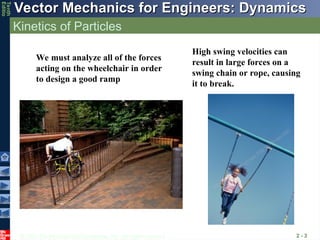
Kinetics of Particles
2 - 3
We must analyze all of the forces
acting on the wheelchair in order
to design a good ramp
High swing velocities can
result in large forces on a
swing chain or rope, causing
it to break.
- 4.
© 2013 TheMcGraw-Hill Companies, Inc. All rights reserved.
Vector Mechanics for Engineers: Dynamics
Vector Mechanics for Engineers: Dynamics
Tenth
Editio
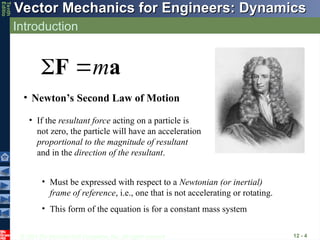
Introduction
12 - 4
• Newton’s Second Law of Motion
m
F a
• If the resultant force acting on a particle is
not zero, the particle will have an acceleration
proportional to the magnitude of resultant
and in the direction of the resultant.
• Must be expressed with respect to a Newtonian (or inertial)
frame of reference, i.e., one that is not accelerating or rotating.
• This form of the equation is for a constant mass system
- 5.
© 2013 TheMcGraw-Hill Companies, Inc. All rights reserved.
Vector Mechanics for Engineers: Dynamics
Vector Mechanics for Engineers: Dynamics
Tenth
Editio
Linear Momentum of a Particle
12 - 5
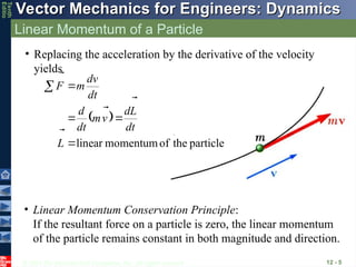
• Replacing the acceleration by the derivative of the velocity
yields
particle
the
of
momentum
linear
L
dt
L
d
v
m
dt
d
dt
v
d
m
F
• Linear Momentum Conservation Principle:
If the resultant force on a particle is zero, the linear momentum
of the particle remains constant in both magnitude and direction.
- 6.
© 2013 TheMcGraw-Hill Companies, Inc. All rights reserved.
Vector Mechanics for Engineers: Dynamics
Vector Mechanics for Engineers: Dynamics
Tenth
Editio
Systems of Units
12 - 6
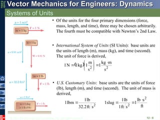
• Of the units for the four primary dimensions (force,
mass, length, and time), three may be chosen arbitrarily.
The fourth must be compatible with Newton’s 2nd Law.
• International System of Units (SI Units): base units are
the units of length (m), mass (kg), and time (second).
The unit of force is derived,
2
2
s
m
kg
1
s
m
1
kg
1
N
1
• U.S. Customary Units: base units are the units of force
(lb), length (m), and time (second). The unit of mass is
derived,
ft
s
lb
1
s
ft
1
lb
1
slug
1
s
ft
32.2
lb
1
lbm
1
2
2
2
- 7.
© 2013 TheMcGraw-Hill Companies, Inc. All rights reserved.
Vector Mechanics for Engineers: Dynamics
Vector Mechanics for Engineers: Dynamics
Tenth
Editio
Equations of Motion
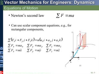
12 - 7
• Newton’s second law a
m
F
• Can use scalar component equations, e.g., for
rectangular components,
z
m
F
y
m
F
x
m
F
ma
F
ma
F
ma
F
k
a
j
a
i
a
m
k
F
j
F
i
F
z
y
x
z
z
y
y
x
x
z
y
x
z
y
x
- 8.
© 2013 TheMcGraw-Hill Companies, Inc. All rights reserved.
Vector Mechanics for Engineers: Dynamics
Vector Mechanics for Engineers: Dynamics
Tenth
Editio
Dynamic Equilibrium
12 - 8
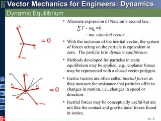
• Alternate expression of Newton’s second law,
ector
inertial v
a
m
a
m
F 0
• With the inclusion of the inertial vector, the system
of forces acting on the particle is equivalent to
zero. The particle is in dynamic equilibrium.
• Methods developed for particles in static
equilibrium may be applied, e.g., coplanar forces
may be represented with a closed vector polygon.
• Inertia vectors are often called inertial forces as
they measure the resistance that particles offer to
changes in motion, i.e., changes in speed or
direction.
• Inertial forces may be conceptually useful but are
not like the contact and gravitational forces found
in statics.
- 9.
© 2013 TheMcGraw-Hill Companies, Inc. All rights reserved.
Vector Mechanics for Engineers: Dynamics
Vector Mechanics for Engineers: Dynamics
Tenth
Editio
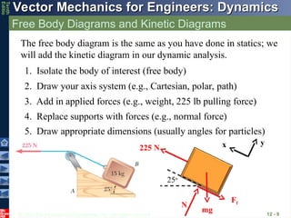
Free Body Diagrams and Kinetic Diagrams
12 - 9
The free body diagram is the same as you have done in statics; we
will add the kinetic diagram in our dynamic analysis.
2. Draw your axis system (e.g., Cartesian, polar, path)
3. Add in applied forces (e.g., weight, 225 lb pulling force)
4. Replace supports with forces (e.g., normal force)
1. Isolate the body of interest (free body)
5. Draw appropriate dimensions (usually angles for particles)
x y
225 N
Ff
N
mg
25o
- 10.
© 2013 TheMcGraw-Hill Companies, Inc. All rights reserved.
Vector Mechanics for Engineers: Dynamics
Vector Mechanics for Engineers: Dynamics
Tenth
Editio
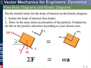
Free Body Diagrams and Kinetic Diagrams
12 - 10
Put the inertial terms for the body of interest on the kinetic diagram.
2. Draw in the mass times acceleration of the particle; if unknown,
do this in the positive direction according to your chosen axes
1. Isolate the body of interest (free body)
x y
225 N
Ff
N
mg
25o
may
max
m
F a
- 11.
© 2013 TheMcGraw-Hill Companies, Inc. All rights reserved.
Vector Mechanics for Engineers: Dynamics
Vector Mechanics for Engineers: Dynamics
Tenth
Editio
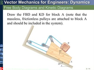
Free Body Diagrams and Kinetic Diagrams
2 - 11
Draw the FBD and KD for block A (note that the
massless, frictionless pulleys are attached to block A
and should be included in the system).
- 12.
© 2013 TheMcGraw-Hill Companies, Inc. All rights reserved.
Vector Mechanics for Engineers: Dynamics
Vector Mechanics for Engineers: Dynamics
Tenth
Editio
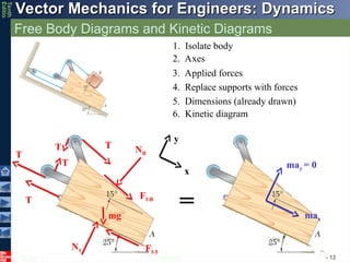
Free Body Diagrams and Kinetic Diagrams
2 - 12
1. Isolate body
2. Axes
3. Applied forces
4. Replace supports with forces
5. Dimensions (already drawn)
x
y
mg
Ff-1
N1
T
T
T
T
T
Ff-B
NB
may = 0
max
6. Kinetic diagram
=
- 13.
© 2013 TheMcGraw-Hill Companies, Inc. All rights reserved.
Vector Mechanics for Engineers: Dynamics
Vector Mechanics for Engineers: Dynamics
Tenth
Editio
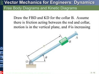
Free Body Diagrams and Kinetic Diagrams
2 - 13
Draw the FBD and KD for the collar B. Assume
there is friction acting between the rod and collar,
motion is in the vertical plane, and is increasing
- 14.
© 2013 TheMcGraw-Hill Companies, Inc. All rights reserved.
Vector Mechanics for Engineers: Dynamics
Vector Mechanics for Engineers: Dynamics
Tenth
Editio
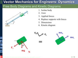
Free Body Diagrams and Kinetic Diagrams
2 - 14
1. Isolate body
2. Axes
3. Applied forces
4. Replace supports with forces
5. Dimensions
6. Kinetic diagram
mg
Ff
N
mar
ma
e er
=
- 15.
© 2013 TheMcGraw-Hill Companies, Inc. All rights reserved.
Vector Mechanics for Engineers: Dynamics
Vector Mechanics for Engineers: Dynamics
Tenth
Editio
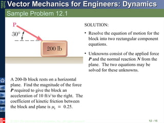
Sample Problem 12.1
12 - 15
A 200-lb block rests on a horizontal
plane. Find the magnitude of the force
P required to give the block an
acceleration of 10 ft/s2
to the right. The
coefficient of kinetic friction between
the block and plane is k0.25.
SOLUTION:
• Resolve the equation of motion for the
block into two rectangular component
equations.
• Unknowns consist of the applied force
P and the normal reaction N from the
plane. The two equations may be
solved for these unknowns.
- 16.
© 2013 TheMcGraw-Hill Companies, Inc. All rights reserved.
Vector Mechanics for Engineers: Dynamics
Vector Mechanics for Engineers: Dynamics
Tenth
Editio
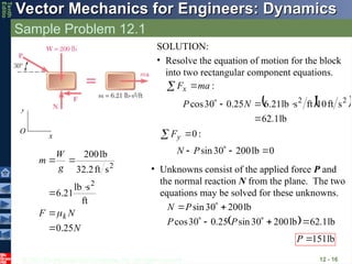
Sample Problem 12.1
12 - 16
N
N
F
g
W
m
k
25
.
0
ft
s
lb
21
.
6
s
ft
2
.
32
lb
200
2
2
x
y
O
SOLUTION:
• Resolve the equation of motion for the block
into two rectangular component equations.
:
ma
Fx
lb
1
.
62
s
ft
10
ft
s
lb
21
.
6
25
.
0
30
cos 2
2
N
P
:
0
y
F
0
lb
200
30
sin
P
N
• Unknowns consist of the applied force P and
the normal reaction N from the plane. The two
equations may be solved for these unknowns.
lb
1
.
62
lb
200
30
sin
25
.
0
30
cos
lb
200
30
sin
P
P
P
N
lb
151
P
- 17.
© 2013 TheMcGraw-Hill Companies, Inc. All rights reserved.
Vector Mechanics for Engineers: Dynamics
Vector Mechanics for Engineers: Dynamics
Tenth
Editio
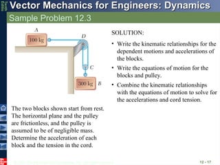
Sample Problem 12.3
12 - 17
The two blocks shown start from rest.
The horizontal plane and the pulley
are frictionless, and the pulley is
assumed to be of negligible mass.
Determine the acceleration of each
block and the tension in the cord.
SOLUTION:
• Write the kinematic relationships for the
dependent motions and accelerations of
the blocks.
• Write the equations of motion for the
blocks and pulley.
• Combine the kinematic relationships
with the equations of motion to solve for
the accelerations and cord tension.
- 18.
© 2013 TheMcGraw-Hill Companies, Inc. All rights reserved.
Vector Mechanics for Engineers: Dynamics
Vector Mechanics for Engineers: Dynamics
Tenth
Editio
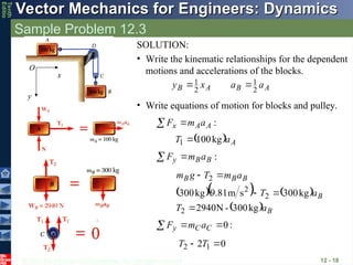
Sample Problem 12.3
12 - 18
• Write equations of motion for blocks and pulley.
:
A
A
x a
m
F
A
a
T kg
100
1
:
B
B
y a
m
F
B
B
B
B
B
a
T
a
T
a
m
T
g
m
kg
300
-
N
2940
kg
300
s
m
81
.
9
kg
300
2
2
2
2
:
0
C
C
y a
m
F
0
2 1
2
T
T
SOLUTION:
• Write the kinematic relationships for the dependent
motions and accelerations of the blocks.
A
B
A
B a
a
x
y 2
1
2
1
x
y
O
- 19.
© 2013 TheMcGraw-Hill Companies, Inc. All rights reserved.
Vector Mechanics for Engineers: Dynamics
Vector Mechanics for Engineers: Dynamics
Tenth
Editio
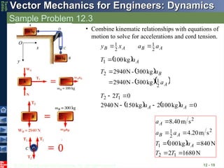
Sample Problem 12.3
12 - 19
N
1680
2
N
840
kg
100
s
m
20
.
4
s
m
40
.
8
1
2
1
2
2
1
2
T
T
a
T
a
a
a
A
A
B
A
• Combine kinematic relationships with equations of
motion to solve for accelerations and cord tension.
A
B
A
B a
a
x
y 2
1
2
1
A
a
T kg
100
1
A
B
a
a
T
2
1
2
kg
300
-
N
2940
kg
300
-
N
2940
0
kg
100
2
kg
150
N
2940
0
2 1
2
A
A a
a
T
T
x
y
O
- 20.
© 2013 TheMcGraw-Hill Companies, Inc. All rights reserved.
Vector Mechanics for Engineers: Dynamics
Vector Mechanics for Engineers: Dynamics
Tenth
Editio
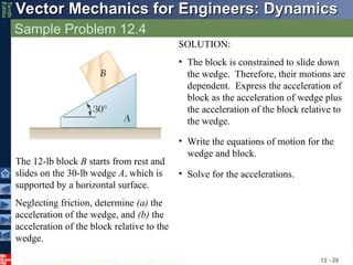
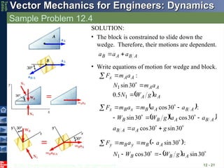
Sample Problem 12.4
12 - 20
The 12-lb block B starts from rest and
slides on the 30-lb wedge A, which is
supported by a horizontal surface.
Neglecting friction, determine (a) the
acceleration of the wedge, and (b) the
acceleration of the block relative to the
wedge.
SOLUTION:
• The block is constrained to slide down
the wedge. Therefore, their motions are
dependent. Express the acceleration of
block as the acceleration of wedge plus
the acceleration of the block relative to
the wedge.
• Write the equations of motion for the
wedge and block.
• Solve for the accelerations.
- 21.
© 2013 TheMcGraw-Hill Companies, Inc. All rights reserved.
Vector Mechanics for Engineers: Dynamics
Vector Mechanics for Engineers: Dynamics
Tenth
Editio
Sample Problem 12.4
12 - 21
SOLUTION:
• The block is constrained to slide down the
wedge. Therefore, their motions are dependent.
A
B
A
B a
a
a
• Write equations of motion for wedge and block.
x
y
:
A
A
x a
m
F
A
A
A
A
a
g
W
N
a
m
N
1
1
5
.
0
30
sin
:
30
cos A
B
A
B
x
B
x a
a
m
a
m
F
30
sin
30
cos
30
cos
30
sin
g
a
a
a
a
g
W
W
A
A
B
A
B
A
B
B
:
30
sin
A
B
y
B
y a
m
a
m
F
30
sin
30
cos
1 A
B
B a
g
W
W
N
- 22.
© 2013 TheMcGraw-Hill Companies, Inc. All rights reserved.
Vector Mechanics for Engineers: Dynamics
Vector Mechanics for Engineers: Dynamics
Tenth
Editio
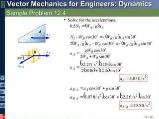
Sample Problem 12.4
12 - 22
A
A a
g
W
N
1
5
.
0
• Solve for the accelerations.
30
sin
lb
12
lb
30
2
30
cos
lb
12
s
ft
2
.
32
30
sin
2
30
cos
30
sin
30
cos
2
30
sin
30
cos
2
1
A
B
A
B
A
A
B
B
A
A
A
B
B
a
W
W
gW
a
a
g
W
W
a
g
W
a
g
W
W
N
2
s
ft
07
.
5
A
a
30
sin
s
ft
2
.
32
30
cos
s
ft
07
.
5
30
sin
30
cos
2
2
A
B
A
A
B
a
g
a
a
2
s
ft
5
.
20
A
B
a
- 23.
© 2013 TheMcGraw-Hill Companies, Inc. All rights reserved.
Vector Mechanics for Engineers: Dynamics
Vector Mechanics for Engineers: Dynamics
Tenth
Editio
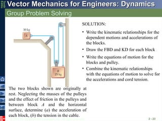
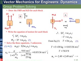
Group Problem Solving
2 - 23
The two blocks shown are originally at
rest. Neglecting the masses of the pulleys
and the effect of friction in the pulleys and
between block A and the horizontal
surface, determine (a) the acceleration of
each block, (b) the tension in the cable.
SOLUTION:
• Write the kinematic relationships for the
dependent motions and accelerations of
the blocks.
• Write the equations of motion for the
blocks and pulley.
• Combine the kinematic relationships
with the equations of motion to solve for
the accelerations and cord tension.
• Draw the FBD and KD for each block
- 24.
© 2013 TheMcGraw-Hill Companies, Inc. All rights reserved.
Vector Mechanics for Engineers: Dynamics
Vector Mechanics for Engineers: Dynamics
Tenth
Editio
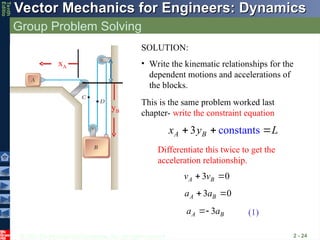
Group Problem Solving
2 - 24
xA
yB
const nts
3 a
A B
x y L
3 0
A B
v v
3 0
A B
a a
3
A B
a a
SOLUTION:
• Write the kinematic relationships for the
dependent motions and accelerations of
the blocks.
This is the same problem worked last
chapter- write the constraint equation
Differentiate this twice to get the
acceleration relationship.
(1)
- 25.
© 2013 TheMcGraw-Hill Companies, Inc. All rights reserved.
Vector Mechanics for Engineers: Dynamics
Vector Mechanics for Engineers: Dynamics
Tenth
Editio
Group Problem Solving
2 - 25
:
x A A
F m a
A B
T m a
3 A B
T m a
y B B
F m a
3(3 )
B A B B B
m g m a m a
2
2
9.81 m/s
0.83136 m/s
30 kg
1 9
1 9
25 kg
B
A
B
g
a
m
m
2
2.49 2.49 m/s
A
a
2
3 30 kg 0.83136 m/s
T
74.8 N
T
• Draw the FBD and KD for each block
mAg
T
NA
maAx
mBg
2T T
maBy
• Write the equation of motion for each block
=
=
From Eq (1)
(2) (3)
3
B B B
W T m a
(2)
(3)
B
A
• Solve the three equations, 3 unknowns
+y
+x
- 26.
© 2013 TheMcGraw-Hill Companies, Inc. All rights reserved.
Vector Mechanics for Engineers: Dynamics
Vector Mechanics for Engineers: Dynamics
Tenth
Editio
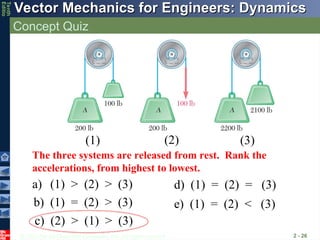
Concept Quiz
2 - 26
The three systems are released from rest. Rank the
accelerations, from highest to lowest.
a) (1) > (2) > (3)
b) (1) = (2) > (3)
c) (2) > (1) > (3)
d) (1) = (2) = (3)
e) (1) = (2) < (3)
(1) (2) (3)
- 27.
© 2013 TheMcGraw-Hill Companies, Inc. All rights reserved.
Vector Mechanics for Engineers: Dynamics
Vector Mechanics for Engineers: Dynamics
Tenth
Editio
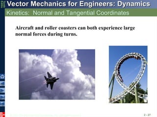
Kinetics: Normal and Tangential Coordinates
2 - 27
Aircraft and roller coasters can both experience large
normal forces during turns.
- 28.
© 2013 TheMcGraw-Hill Companies, Inc. All rights reserved.
Vector Mechanics for Engineers: Dynamics
Vector Mechanics for Engineers: Dynamics
Tenth
Editio
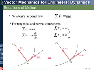
Equations of Motion
12 - 28
• For tangential and normal components,
t t
t
F ma
dv
F m
dt
• Newton’s second law a
m
F
2
n n
n
F ma
v
F m
- 29.
© 2013 TheMcGraw-Hill Companies, Inc. All rights reserved.
Vector Mechanics for Engineers: Dynamics
Vector Mechanics for Engineers: Dynamics
Tenth
Editio
Sample Problem 12.5
12 - 29
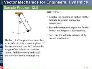
The bob of a 2-m pendulum describes
an arc of a circle in a vertical plane. If
the tension in the cord is 2.5 times the
weight of the bob for the position
shown, find the velocity and accel-
eration of the bob in that position.
SOLUTION:
• Resolve the equation of motion for the
bob into tangential and normal
components.
• Solve the component equations for the
normal and tangential accelerations.
• Solve for the velocity in terms of the
normal acceleration.
- 30.
© 2013 TheMcGraw-Hill Companies, Inc. All rights reserved.
Vector Mechanics for Engineers: Dynamics
Vector Mechanics for Engineers: Dynamics
Tenth
Editio
Sample Problem 12.5
12 - 30
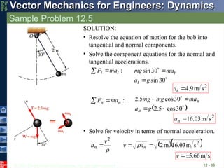
SOLUTION:
• Resolve the equation of motion for the bob into
tangential and normal components.
• Solve the component equations for the normal and
tangential accelerations.
:
t
t ma
F
30
sin
30
sin
g
a
ma
mg
t
t
2
s
m
9
.
4
t
a
:
n
n ma
F
30
cos
5
.
2
30
cos
5
.
2
g
a
ma
mg
mg
n
n
2
s
m
03
.
16
n
a
• Solve for velocity in terms of normal acceleration.
2
2
s
m
03
.
16
m
2
n
n a
v
v
a
s
m
66
.
5
v
- 31.
© 2013 TheMcGraw-Hill Companies, Inc. All rights reserved.
Vector Mechanics for Engineers: Dynamics
Vector Mechanics for Engineers: Dynamics
Tenth
Editio
Sample Problem 12.6
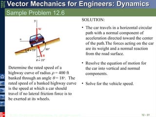
12 - 31
Determine the rated speed of a
highway curve of radius = 400 ft
banked through an angle = 18o
. The
rated speed of a banked highway curve
is the speed at which a car should
travel if no lateral friction force is to
be exerted at its wheels.
SOLUTION:
• The car travels in a horizontal circular
path with a normal component of
acceleration directed toward the center
of the path.The forces acting on the car
are its weight and a normal reaction
from the road surface.
• Resolve the equation of motion for
the car into vertical and normal
components.
• Solve for the vehicle speed.
- 32.
© 2013 TheMcGraw-Hill Companies, Inc. All rights reserved.
Vector Mechanics for Engineers: Dynamics
Vector Mechanics for Engineers: Dynamics
Tenth
Editio
Sample Problem 12.6
12 - 32
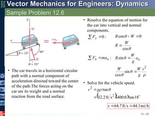
SOLUTION:
• The car travels in a horizontal circular
path with a normal component of
acceleration directed toward the center
of the path.The forces acting on the
car are its weight and a normal
reaction from the road surface.
• Resolve the equation of motion for
the car into vertical and normal
components.
:
0
y
F
cos
0
cos
W
R
W
R
:
n
n ma
F
2
sin
cos
sin
v
g
W
W
a
g
W
R n
• Solve for the vehicle speed.
18
tan
ft
400
s
ft
2
.
32
tan
2
2
g
v
h
mi
1
.
44
s
ft
7
.
64
v
- 33.
© 2013 TheMcGraw-Hill Companies, Inc. All rights reserved.
Vector Mechanics for Engineers: Dynamics
Vector Mechanics for Engineers: Dynamics
Tenth
Editio
Group Problem Solving
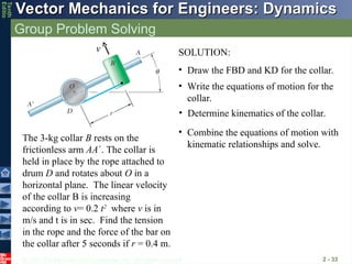
2 - 33
The 3-kg collar B rests on the
frictionless arm AA. The collar is
held in place by the rope attached to
drum D and rotates about O in a
horizontal plane. The linear velocity
of the collar B is increasing
according to v= 0.2 t2
where v is in
m/s and t is in sec. Find the tension
in the rope and the force of the bar on
the collar after 5 seconds if r = 0.4 m.
v SOLUTION:
• Write the equations of motion for the
collar.
• Combine the equations of motion with
kinematic relationships and solve.
• Draw the FBD and KD for the collar.
• Determine kinematics of the collar.
- 34.
© 2013 TheMcGraw-Hill Companies, Inc. All rights reserved.
Vector Mechanics for Engineers: Dynamics
Vector Mechanics for Engineers: Dynamics
Tenth
Editio
Group Problem Solving
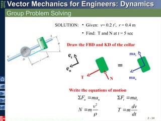
2 - 34
SOLUTION: • Given: v= 0.2 t2
, r = 0.4 m
• Find: T and N at t = 5 sec
Draw the FBD and KD of the collar
man
T N
et
en
mat
Write the equations of motion
=
n n
F ma
t t
F ma
2
v
N m
dv
T m
dt
- 35.
© 2013 TheMcGraw-Hill Companies, Inc. All rights reserved.
Vector Mechanics for Engineers: Dynamics
Vector Mechanics for Engineers: Dynamics
Tenth
Editio
Group Problem Solving
2 - 35
man
T N
et
en
mat
=
2 2
2
5
62.5 (m/s )
0.4
n
v
a
2
0.4 0.4(5) 2 m/s
t
dv
a t
dt
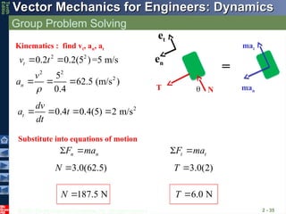
Kinematics : find vt, an, at
2 2
0.2 0.2(5 )=5 m/s
t
v t
Substitute into equations of motion
3.0(62.5)
N 3.0(2)
T
187.5 N
N 6.0 N
T
n n
F ma
t t
F ma
- 36.
© 2013 TheMcGraw-Hill Companies, Inc. All rights reserved.
Vector Mechanics for Engineers: Dynamics
Vector Mechanics for Engineers: Dynamics
Tenth
Editio
Group Problem Solving
2 - 36
man
T N
et
en
mat
=
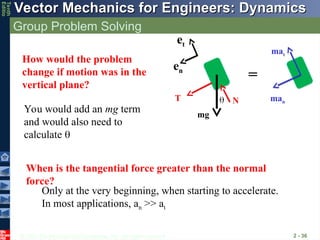
How would the problem
change if motion was in the
vertical plane?
mg
You would add an mg term
and would also need to
calculate
When is the tangential force greater than the normal
force?
Only at the very beginning, when starting to accelerate.
In most applications, an >> at
- 37.
© 2013 TheMcGraw-Hill Companies, Inc. All rights reserved.
Vector Mechanics for Engineers: Dynamics
Vector Mechanics for Engineers: Dynamics
Tenth
Editio
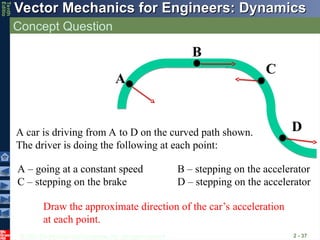
Concept Question
2 - 37
D
B
C
A
A car is driving from A to D on the curved path shown.
The driver is doing the following at each point:
A – going at a constant speed B – stepping on the accelerator
C – stepping on the brake D – stepping on the accelerator
Draw the approximate direction of the car’s acceleration
at each point.
- 38.
© 2013 TheMcGraw-Hill Companies, Inc. All rights reserved.
Vector Mechanics for Engineers: Dynamics
Vector Mechanics for Engineers: Dynamics
Tenth
Editio
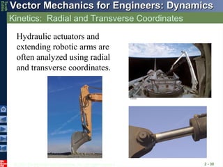
Kinetics: Radial and Transverse Coordinates
2 - 38
Hydraulic actuators and
extending robotic arms are
often analyzed using radial
and transverse coordinates.
- 39.
© 2013 TheMcGraw-Hill Companies, Inc. All rights reserved.
Vector Mechanics for Engineers: Dynamics
Vector Mechanics for Engineers: Dynamics
Tenth
Editio
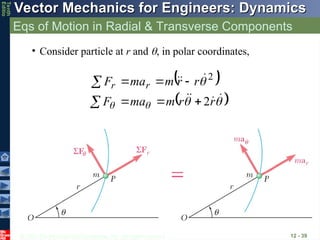
Eqs of Motion in Radial & Transverse Components
12 - 39
r
r
m
ma
F
r
r
m
ma
F r
r
2
2
• Consider particle at r and , in polar coordinates,
- 40.
© 2013 TheMcGraw-Hill Companies, Inc. All rights reserved.
Vector Mechanics for Engineers: Dynamics
Vector Mechanics for Engineers: Dynamics
Tenth
Editio
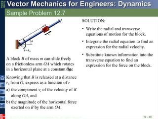
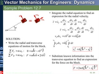
Sample Problem 12.7
12 - 40
A block B of mass m can slide freely
on a frictionless arm OA which rotates
in a horizontal plane at a constant rate
.
0
a) the component vr of the velocity of B
along OA, and
b) the magnitude of the horizontal force
exerted on B by the arm OA.
Knowing that B is released at a distance
r0 from O, express as a function of r
SOLUTION:
• Write the radial and transverse
equations of motion for the block.
• Integrate the radial equation to find an
expression for the radial velocity.
• Substitute known information into the
transverse equation to find an
expression for the force on the block.
- 41.
© 2013 TheMcGraw-Hill Companies, Inc. All rights reserved.
Vector Mechanics for Engineers: Dynamics
Vector Mechanics for Engineers: Dynamics
Tenth
Editio
Sample Problem 12.7
12 - 41
SOLUTION:
• Write the radial and transverse
equations of motion for the block.
:
:
a
m
F
a
m
F r
r
r
r
m
F
r
r
m
2
0 2
• Integrate the radial equation to find an
expression for the radial velocity.
r
r
v
r
r
r
r
r
r
r
r
r
dr
r
dv
v
dr
r
dr
r
dv
v
dr
dv
v
dt
dr
dr
dv
dt
dv
v
r
r
0
2
0
0
2
0
2
dr
dv
v
dt
dr
dr
dv
dt
dv
v
r r
r
r
r
r
2
0
2
2
0
2
r
r
vr
• Substitute known information into the
transverse equation to find an expression
for the force on the block.
2
1
2
0
2
2
0
2 r
r
m
F
- 42.
© 2013 TheMcGraw-Hill Companies, Inc. All rights reserved.
Vector Mechanics for Engineers: Dynamics
Vector Mechanics for Engineers: Dynamics
Tenth
Editio
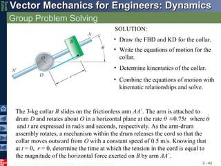
Group Problem Solving
2 - 42
• Write the equations of motion for the
collar.
• Combine the equations of motion with
kinematic relationships and solve.
• Draw the FBD and KD for the collar.
• Determine kinematics of the collar.
SOLUTION:
The 3-kg collar B slides on the frictionless arm AA. The arm is attached to
drum D and rotates about O in a horizontal plane at the rate where
and t are expressed in rad/s and seconds, respectively. As the arm-drum
assembly rotates, a mechanism within the drum releases the cord so that the
collar moves outward from O with a constant speed of 0.5 m/s. Knowing that
at t = 0, r = 0, determine the time at which the tension in the cord is equal to
the magnitude of the horizontal force exerted on B by arm AA.
0.75t
- 43.
© 2013 TheMcGraw-Hill Companies, Inc. All rights reserved.
Vector Mechanics for Engineers: Dynamics
Vector Mechanics for Engineers: Dynamics
Tenth
Editio
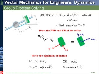
Group Problem Solving
2 - 43
mar
T N
e
er
ma
=
r r
F ma
B
F m a
Draw the FBD and KD of the collar
Write the equations of motion
SOLUTION: • Given:
• Find: time when T = N
2
( )
T m r r
( 2 )
N m r r
0.75t
5 m/s
r
(0) 0
r
- 44.
© 2013 TheMcGraw-Hill Companies, Inc. All rights reserved.
Vector Mechanics for Engineers: Dynamics
Vector Mechanics for Engineers: Dynamics
Tenth
Editio
Group Problem Solving
2 - 44
3 2
: (3 kg)( 0.28125 ) m/s
r r
F ma T t
2
: (3 kg)(1.125 ) m/s
B
F m a N t
0 0
0.5
r t
dr dt
(0.5 ) m
r t
0
r
2
(0.75 ) rad/s
0.75 rad/s
t
2 2 3 2
0 [(0.5 ) m][(0.75 ) rad/s] (0.28125 ) m/s
r
a r r t t t
2
2
2 [(0.5 ) m][0.75 rad/s ] 2(0.5 m/s)[(0.75 ) rad/s]
(1.125 ) m/s
a r r t t
t
Kinematics : find expressions for r and
Substitute values into ar , a
Substitute into equation of motion
3
(0.84375 ) (3.375 )
t t
2
4.000
t
2.00 s
t
Set T = N
5 m/s
r
- 45.
© 2013 TheMcGraw-Hill Companies, Inc. All rights reserved.
Vector Mechanics for Engineers: Dynamics
Vector Mechanics for Engineers: Dynamics
Tenth
Editio
Concept Quiz
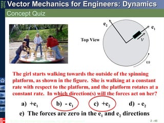
2 - 45
Top View
e1
e2
v
The girl starts walking towards the outside of the spinning
platform, as shown in the figure. She is walking at a constant
rate with respect to the platform, and the platform rotates at a
constant rate. In which direction(s) will the forces act on her?
a) +e1 b) - e1 c) +e2 d) - e2
e) The forces are zero in the e1 and e2 directions
- 46.
© 2013 TheMcGraw-Hill Companies, Inc. All rights reserved.
Vector Mechanics for Engineers: Dynamics
Vector Mechanics for Engineers: Dynamics
Tenth
Editio
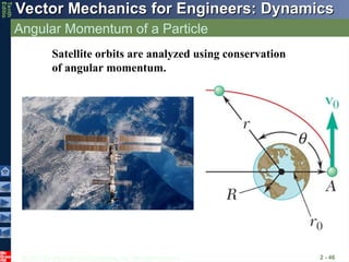
Angular Momentum of a Particle
2 - 46
Satellite orbits are analyzed using conservation
of angular momentum.
- 47.
© 2013 TheMcGraw-Hill Companies, Inc. All rights reserved.
Vector Mechanics for Engineers: Dynamics
Vector Mechanics for Engineers: Dynamics
Tenth
Editio
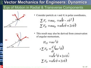
Eqs of Motion in Radial & Transverse Components
12 - 47
r
r
m
ma
F
r
r
m
ma
F r
r
2
2
• Consider particle at r and , in polar coordinates,
r
r
m
F
r
r
r
m
mr
dt
d
F
r
mr
HO
2
2
2
2
2
• This result may also be derived from conservation
of angular momentum,
- 48.
© 2013 TheMcGraw-Hill Companies, Inc. All rights reserved.
Vector Mechanics for Engineers: Dynamics
Vector Mechanics for Engineers: Dynamics
Tenth
Editio
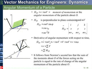
Angular Momentum of a Particle
12 - 48
• moment of momentum or the
angular momentum of the particle about O.
V
m
r
HO
• Derivative of angular momentum with respect to time,
O
O
M
F
r
a
m
r
V
m
V
V
m
r
V
m
r
H
• It follows from Newton’s second law that the sum of
the moments about O of the forces acting on the
particle is equal to the rate of change of the angular
momentum of the particle about O.
z
y
x
O
mv
mv
mv
z
y
x
k
j
i
H
• is perpendicular to plane containing
O
H
V
m
r
and
2
sin
mr
v
rm
rmV
HO
- 49.
© 2013 TheMcGraw-Hill Companies, Inc. All rights reserved.
Vector Mechanics for Engineers: Dynamics
Vector Mechanics for Engineers: Dynamics
Tenth
Editio
Conservation of Angular Momentum
12 - 49
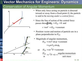
• When only force acting on particle is directed
toward or away from a fixed point O, the particle
is said to be moving under a central force.
• Since the line of action of the central force
passes through O, and
0
O
O H
M
constant
O
H
V
m
r
• Position vector and motion of particle are in a
plane perpendicular to .
O
H
• Magnitude of angular momentum,
0
0
0 sin
constant
sin
V
m
r
V
rm
HO
mass
unit
momentum
angular
constant
2
2
h
r
m
H
mr
H
O
O
or
- 50.
© 2013 TheMcGraw-Hill Companies, Inc. All rights reserved.
Vector Mechanics for Engineers: Dynamics
Vector Mechanics for Engineers: Dynamics
Tenth
Editio
Conservation of Angular Momentum
12 - 50
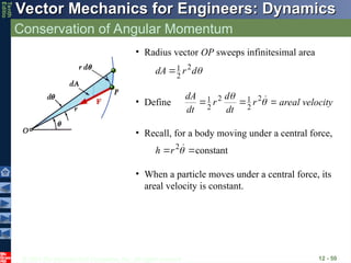
• Radius vector OP sweeps infinitesimal area
d
r
dA 2
2
1
• Define
2
2
1
2
2
1 r
dt
d
r
dt
dA
areal velocity
• Recall, for a body moving under a central force,
constant
2
r
h
• When a particle moves under a central force, its
areal velocity is constant.
- 51.
© 2013 TheMcGraw-Hill Companies, Inc. All rights reserved.
Vector Mechanics for Engineers: Dynamics
Vector Mechanics for Engineers: Dynamics
Tenth
Editio
Newton’s Law of Gravitation
12 - 51
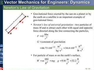
• Gravitational force exerted by the sun on a planet or by
the earth on a satellite is an important example of
gravitational force.
• Newton’s law of universal gravitation - two particles of
mass M and m attract each other with equal and opposite
force directed along the line connecting the particles,
4
4
9
2
3
12
2
s
lb
ft
10
4
.
34
s
kg
m
10
73
.
66
n
gravitatio
of
constant
G
r
Mm
G
F
• For particle of mass m on the earth’s surface,
2
2
2
s
ft
2
.
32
s
m
81
.
9
g
mg
R
MG
m
W
- 52.
© 2013 TheMcGraw-Hill Companies, Inc. All rights reserved.
Vector Mechanics for Engineers: Dynamics
Vector Mechanics for Engineers: Dynamics
Tenth
Editio
Sample Problem 12.8
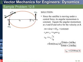
12 - 52
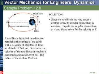
A satellite is launched in a direction
parallel to the surface of the earth
with a velocity of 18820 mi/h from
an altitude of 240 mi. Determine the
velocity of the satellite as it reaches it
maximum altitude of 2340 mi. The
radius of the earth is 3960 mi.
SOLUTION:
• Since the satellite is moving under a
central force, its angular momentum is
constant. Equate the angular momentum
at A and B and solve for the velocity at B.
- 53.
© 2013 TheMcGraw-Hill Companies, Inc. All rights reserved.
Vector Mechanics for Engineers: Dynamics
Vector Mechanics for Engineers: Dynamics
Tenth
Editio
Sample Problem 12.8
12 - 53
SOLUTION:
• Since the satellite is moving under a
central force, its angular momentum is
constant. Equate the angular momentum
at A and B and solve for the velocity at B.
mi
2340
3960
mi
240
3960
h
mi
18820
constant
sin
B
A
A
B
B
B
A
A
O
r
r
v
v
v
m
r
v
m
r
H
v
rm
h
mi
12550
B
v
- 54.
© 2013 TheMcGraw-Hill Companies, Inc. All rights reserved.
Vector Mechanics for Engineers: Dynamics
Vector Mechanics for Engineers: Dynamics
Tenth
Editio
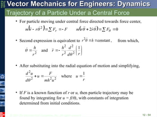
Trajectory of a Particle Under a Central Force
12 - 54
• For particle moving under central force directed towards force center,
0
2
2
F
r
r
m
F
F
r
r
m r
• Second expression is equivalent to from which,
,
constant
2
h
r
r
d
d
r
h
r
r
h 1
and 2
2
2
2
2
• After substituting into the radial equation of motion and simplifying,
r
u
u
mh
F
u
d
u
d 1
where
2
2
2
2
• If F is a known function of r or u, then particle trajectory may be
found by integrating for u = f(), with constants of integration
determined from initial conditions.
- 55.
© 2013 TheMcGraw-Hill Companies, Inc. All rights reserved.
Vector Mechanics for Engineers: Dynamics
Vector Mechanics for Engineers: Dynamics
Tenth
Editio
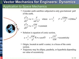
Application to Space Mechanics
12 - 55
constant
1
where
2
2
2
2
2
2
2
2
2
h
GM
u
d
u
d
GMmu
r
GMm
F
r
u
u
mh
F
u
d
u
d
• Consider earth satellites subjected to only gravitational pull
of the earth,
• Solution is equation of conic section,
ty
eccentrici
cos
1
1 2
2
GM
h
C
h
GM
r
u
• Origin, located at earth’s center, is a focus of the conic
section.
• Trajectory may be ellipse, parabola, or hyperbola depending
on value of eccentricity.
- 56.
© 2013 TheMcGraw-Hill Companies, Inc. All rights reserved.
Vector Mechanics for Engineers: Dynamics
Vector Mechanics for Engineers: Dynamics
Tenth
Editio
Application to Space Mechanics
12 - 56
ty
eccentrici
cos
1
1 2
2
GM
h
C
h
GM
r
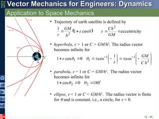
• Trajectory of earth satellite is defined by
• hyperbola, > 1 or C > GM/h2
. The radius vector
becomes infinite for
2
1
1
1
1 cos
1
cos
0
cos
1
h
C
GM
• parabola, = 1 or C = GM/h2
. The radius vector
becomes infinite for
180
0
cos
1 2
2
• ellipse, < 1 or C < GM/h2
. The radius vector is finite
for and is constant, i.e., a circle, for < 0.
- 57.
© 2013 TheMcGraw-Hill Companies, Inc. All rights reserved.
Vector Mechanics for Engineers: Dynamics
Vector Mechanics for Engineers: Dynamics
Tenth
Editio
Application to Space Mechanics
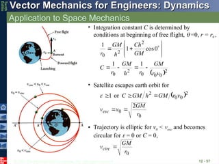
12 - 57
• Integration constant C is determined by
conditions at beginning of free flight, =0, r = r0 ,
2
0
0
0
2
0
2
2
0
1
1
0
cos
1
1
v
r
GM
r
h
GM
r
C
GM
Ch
h
GM
r
0
0
2
0
0
2
2
or
1
r
GM
v
v
v
r
GM
h
GM
C
esc
• Satellite escapes earth orbit for
• Trajectory is elliptic for v0 < vesc and becomes
circular for = 0 or C = 0,
0
r
GM
vcirc
- 58.
© 2013 TheMcGraw-Hill Companies, Inc. All rights reserved.
Vector Mechanics for Engineers: Dynamics
Vector Mechanics for Engineers: Dynamics
Tenth
Editio
Application to Space Mechanics
12 - 58
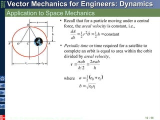
• Recall that for a particle moving under a central
force, the areal velocity is constant, i.e.,
constant
2
1
2
2
1
h
r
dt
dA
• Periodic time or time required for a satellite to
complete an orbit is equal to area within the orbit
divided by areal velocity,
h
ab
h
ab
2
2
where
1
0
1
0
2
1
r
r
b
r
r
a
- 59.
© 2013 TheMcGraw-Hill Companies, Inc. All rights reserved.
Vector Mechanics for Engineers: Dynamics
Vector Mechanics for Engineers: Dynamics
Tenth
Editio
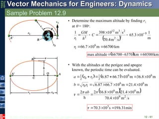
Sample Problem 12.9
12 - 59
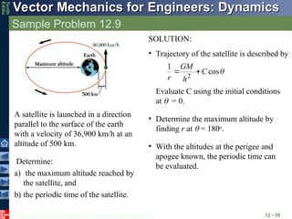
Determine:
a) the maximum altitude reached by
the satellite, and
b) the periodic time of the satellite.
A satellite is launched in a direction
parallel to the surface of the earth
with a velocity of 36,900 km/h at an
altitude of 500 km.
SOLUTION:
• Trajectory of the satellite is described by
cos
1
2
C
h
GM
r
Evaluate C using the initial conditions
at = 0.
• Determine the maximum altitude by
finding r at = 180o
.
• With the altitudes at the perigee and
apogee known, the periodic time can
be evaluated.
- 60.
© 2013 TheMcGraw-Hill Companies, Inc. All rights reserved.
Vector Mechanics for Engineers: Dynamics
Vector Mechanics for Engineers: Dynamics
Tenth
Editio
Sample Problem 12.9
12 - 60
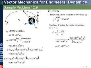
SOLUTION:
• Trajectory of the satellite is described by
cos
1
2
C
h
GM
r
Evaluate C using the initial conditions
at = 0.
2
3
12
2
6
2
2
2
9
3
6
0
0
3
0
6
0
s
m
10
398
m
10
37
.
6
s
m
81
.
9
s
m
10
4
.
70
s
m
10
25
.
10
m
10
6.87
s
m
10
25
.
10
s/h
3600
m/km
1000
h
km
36900
m
10
6.87
km
500
6370
gR
GM
v
r
h
v
r
1
-
9
2
2
2
3
12
6
2
0
m
10
3
.
65
s
m
4
.
70
s
m
10
398
m
10
87
.
6
1
1
h
GM
r
C
- 61.
© 2013 TheMcGraw-Hill Companies, Inc. All rights reserved.
Vector Mechanics for Engineers: Dynamics
Vector Mechanics for Engineers: Dynamics
Tenth
Editio
Sample Problem 12.9
12 - 61
• Determine the maximum altitude by finding r1
at = 180o
.
km
66700
m
10
7
.
66
m
1
10
3
.
65
s
m
4
.
70
s
m
10
398
1
6
1
9
2
2
2
3
12
2
1
r
C
h
GM
r
km
60300
km
6370
-
66700
altitude
max
• With the altitudes at the perigee and apogee
known, the periodic time can be evaluated.
s
m
10
70.4
m
10
21.4
m
10
36.8
2
h
2
m
10
21.4
m
10
7
.
66
87
.
6
m
10
36.8
m
10
7
.
66
87
.
6
2
9
6
6
6
6
1
0
6
6
2
1
1
0
2
1
ab
r
r
b
r
r
a
min
31
h
19
s
10
3
.
70 3
- 62.
© 2013 TheMcGraw-Hill Companies, Inc. All rights reserved.
Vector Mechanics for Engineers: Dynamics
Vector Mechanics for Engineers: Dynamics
Tenth
Editio
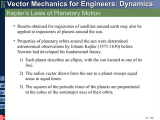
Kepler’s Laws of Planetary Motion
12 - 62
• Results obtained for trajectories of satellites around earth may also be
applied to trajectories of planets around the sun.
• Properties of planetary orbits around the sun were determined
astronomical observations by Johann Kepler (1571-1630) before
Newton had developed his fundamental theory.
1) Each planet describes an ellipse, with the sun located at one of its
foci.
2) The radius vector drawn from the sun to a planet sweeps equal
areas in equal times.
3) The squares of the periodic times of the planets are proportional
to the cubes of the semimajor axes of their orbits.


![© 2013 The McGraw-Hill Companies, Inc. All rights reserved.
Vector Mechanics for Engineers: Dynamics
Vector Mechanics for Engineers: Dynamics
Tenth
Editio
Group Problem Solving
2 - 44
3 2
: (3 kg)( 0.28125 ) m/s
r r
F ma T t
2
: (3 kg)(1.125 ) m/s
B
F m a N t
0 0
0.5
r t
dr dt
(0.5 ) m
r t
0
r
2
(0.75 ) rad/s
0.75 rad/s
t
2 2 3 2
0 [(0.5 ) m][(0.75 ) rad/s] (0.28125 ) m/s
r
a r r t t t
2
2
2 [(0.5 ) m][0.75 rad/s ] 2(0.5 m/s)[(0.75 ) rad/s]
(1.125 ) m/s
a r r t t
t
Kinematics : find expressions for r and
Substitute values into ar , a
Substitute into equation of motion
3
(0.84375 ) (3.375 )
t t
2
4.000
t
2.00 s
t
Set T = N
5 m/s
r
](https://image.slidesharecdn.com/dynamics12lecture-250221140402-f3c7bf47/85/dynamicsclassnoteslecturess12lecture-ppt-44-320.jpg)