The document outlines the design and construction of a hardware add-on for a modular self-reconfigurable robot system called the HiGen Module. It discusses the aims of studying, designing and building an add-on to increase the robot's functionality. The phases included electronics design of the add-on board and chassis, software design using a Raspberry Pi and MATLAB, and testing of the add-on's ability to perform tasks like object tracking using the camera. Further work includes fully integrating the add-on with the robot and developing control algorithms.
![Introduction (MSR)
• Modular Self-Reconfigurable Robots (MSR)
• Concept credited to Fukuda (Dynamically Reconfigurable Robot) [1]
• Designed to fit any given task through reconfiguration
• Lattice, Chain, and Hybrid Architectures
• Homogeneous, Heterogeneous
ATRON: Snake and vehicle-like
[2]
Thor: Heterogeneous MSR
[3]
SuperBot: Bipedal Configuration
[4]](https://image.slidesharecdn.com/c469e807-40f7-451d-b785-25f79dfd0841-161122121610/75/FYP-Presentation-MAREI-4-2048.jpg)
![HiGen Module
• HiGen: High-speed Genderless Mechanical Connection Mechanism for Self-
Reconfigurable Modular Robots
• Genderless nature enables single-sided disconnect
• HiGen Module: Modular robot with four HiGen connectors
HiGen Module
[6]
Standalone HiGen Connector
[5]](https://image.slidesharecdn.com/c469e807-40f7-451d-b785-25f79dfd0841-161122121610/75/FYP-Presentation-MAREI-5-2048.jpg)
![Hardware Extensions (Add-Ons)
• Add functional “tools” to the robot
• Increase the utility of the robot
• Tool examples: sensors (camera modules); functional (grippers, wheels, etc.)
CKBot with camera module
[7]
Add-on Modules of Thor
[2]](https://image.slidesharecdn.com/c469e807-40f7-451d-b785-25f79dfd0841-161122121610/75/FYP-Presentation-MAREI-6-2048.jpg)
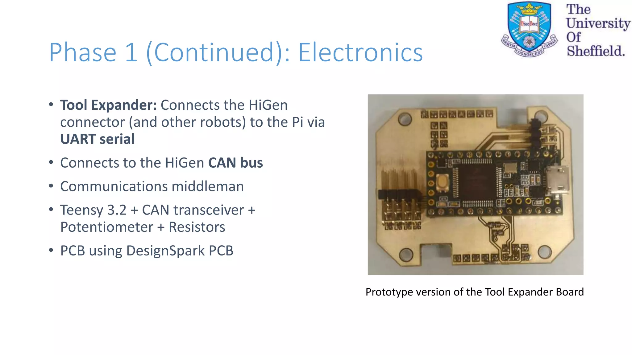
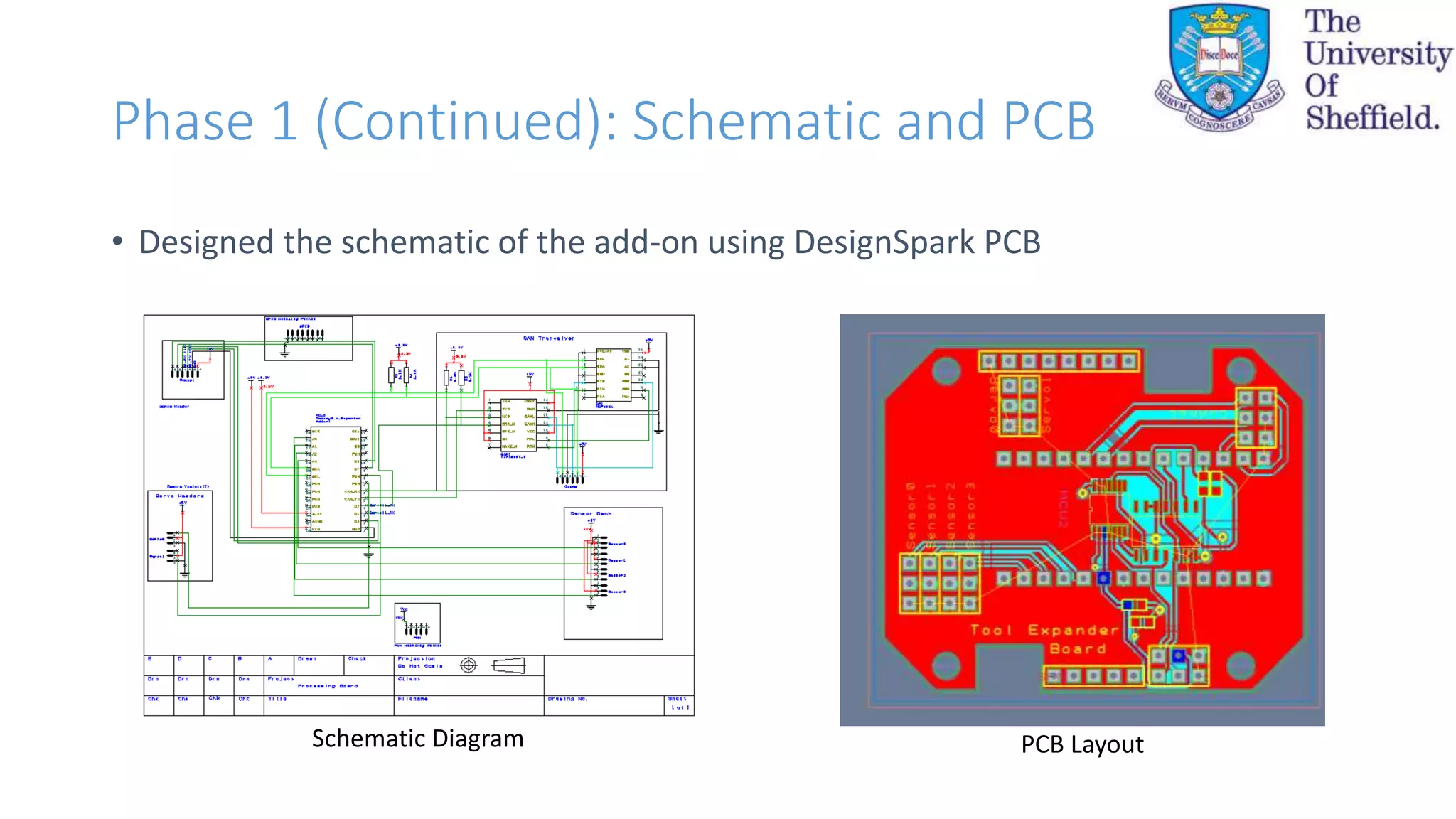
![Phase 1: Electronics Design
• Research into previous implementations of camera add-ons
• Based on Requirements decided with C. Parrott
• SBC (Single-board Computer) as the “brain” of the add-on
• Research into SBC’s Raspberry Pi Model A+ and NoIR Camera
Raspberry Pi Model A+Raspberry Pi NoIR Camera Teensy 3.2 Board Connector Controller
[Parrott]](https://image.slidesharecdn.com/c469e807-40f7-451d-b785-25f79dfd0841-161122121610/75/FYP-Presentation-MAREI-8-2048.jpg)
![Phase 3 (Continued): MATLAB
• Data acquisition
• Lightweight image processing (as opposed to using e.g. OpenCV [8])
• Simulink support package for hardware: Raspberry Pi and ARM
Microcontrollers
• Control design made easier through Simulink
• Integration of the steps in software design (Step 1, Step 2, and Step 3)
• Internet of Things support using ThingSpeak (later)](https://image.slidesharecdn.com/c469e807-40f7-451d-b785-25f79dfd0841-161122121610/75/FYP-Presentation-MAREI-15-2048.jpg)
![Add-On Testing (Control and Data
Acquisition)
• Pan-tilt tracking: modelling using framework outlined by Chen et al. [9]
• Experiment: Object fixed distance and position away from add-on
• Constant position constant tracking angles
• Not the case](https://image.slidesharecdn.com/c469e807-40f7-451d-b785-25f79dfd0841-161122121610/75/FYP-Presentation-MAREI-18-2048.jpg)
![Conclusion and Further Work
Achievements
• Hardware design of the add-on
• Successful programming and testing independent functions
• Attempted to combine functionality but faced problems
• Demonstrated the add-on’s ability to execute application-relevant tasks and acquire data
• Attempted to model and simulate the pan-tilt auto-tracking problem to develop a controller
Further Work
• Finalize integration and test with Connector Controller and HiGen connector
• Verify tracking model and implement on the Raspberry Pi
• Exploit the Raspberry Pi to enable Internet of Things (IoT) access through ThingSpeak [10]](https://image.slidesharecdn.com/c469e807-40f7-451d-b785-25f79dfd0841-161122121610/75/FYP-Presentation-MAREI-19-2048.jpg)

![References
• [1] Fukuda, T., & Nakagawa, S. (1987, October). A dynamically reconfigurable robotic system (concept of a system and optimal
configurations). In Robotics and IECON'87 Conferences (pp. 588-595). International Society for Optics and Photonics.
• [2] Østergaard, E. H., Kassow, K., Beck, R., & Lund, H. H. (2006). Design of the ATRON lattice-based self-reconfigurable robot.
Autonomous Robots, 21(2), 165-183.
• [3] Salemi, B., Moll, M., & Shen, W. M. (2006, October). SUPERBOT: A deployable, multi-functional, and modular self-
reconfigurable robotic system. In Intelligent Robots and Systems, 2006 IEEE/RSJ International Conference on (pp. 3636-3641). IEEE.
• [4] Lyder, A., Garcia, R. F. M., & Stoy, K. (2010). Genderless connection mechanism for modular robots introducing torque
transmission between modules. In Proceedings of the ICRA Workshop on Modular Robots, State of the Art (pp. 77-81).
• [5] Parrott, C., Dodd, T. J., & Gross, R. (2014, September). HiGen: A high-speed genderless mechanical connection mechanism with
single-sided disconnect for self-reconfigurable modular robots. In Intelligent Robots and Systems (IROS 2014), 2014 IEEE/RSJ
International Conference on (pp. 3926-3932). IEEE.
• [6] Parrott, C., Dodd, T. J., & Gross, R. (2014) Towards a 3-DOF mobile and self-reconfigurable modular robot.
• [7] Shirmohammadi, B., Taylor, C. J., Yim, M., Sastra, J., & Park, M. (2007, September). Using smart cameras to localize self-
assembling modular robots. In Distributed Smart Cameras, 2007. ICDSC'07. First ACM/IEEE International Conference on (pp. 76-
80). IEEE.
• [8] Open-Source Computer Vision Library (OpenCV). URL: http://opencv.org/
• [9] Chen, G., St-Charles, P. L., Bouachir, W., Bilodeau, G. A., & Bergevin, R. (2015, September). Reproducible Evaluation of
Pan-Tilt-Zoom Tracking. In Image Processing (ICIP), 2015 IEEE International Conference on (pp. 2055-2059). IEEE.
• [10] The Internet of Things: ThingSpeak. URL: https://thingspeak.com](https://image.slidesharecdn.com/c469e807-40f7-451d-b785-25f79dfd0841-161122121610/75/FYP-Presentation-MAREI-21-2048.jpg)