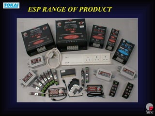
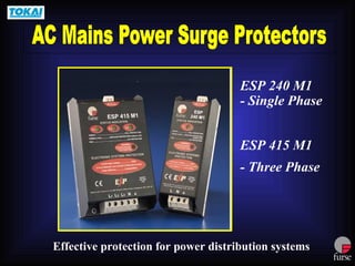
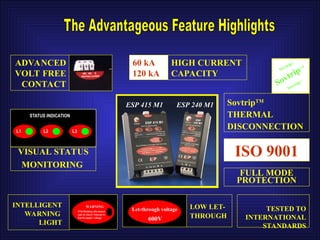
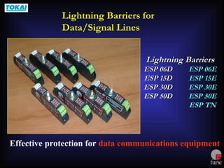
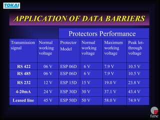
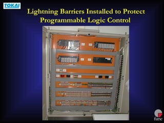
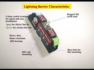
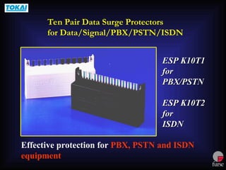
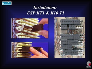
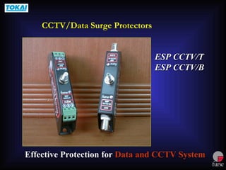
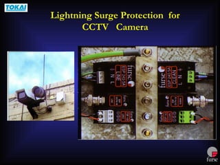
ELECTRONIC
SYSTEMS PROTECTION
E P
ESP RANGE OF PRODUCT
ESP 240 M1
- Single Phase
ESP 415 M1
- Three Phase
Effective protection for power distribution systems
Main Switch Board
Distribution Board
60 kA
120 kA
HIGH CURRENT
CAPACITY
SovtripTM
SovtripTM
SovtripTM
ADVANCED
VOLT FREE
CONTACT
WARNING
If lit/flashing disconnect
unit & check Neutral to
Earth supply voltage
Let-through voltage
600V
VISUAL STATUS
MONITORING
STATUS INDICATION
L1 L2 L3
INTELLIGENT
WARNING
LIGHT
LOW LET-
THROUGH
SovtripTM
THERMAL
DISCONNECTION
ISO 9001
TESTED TO
INTERNATIONAL
STANDARDS
FULL MODE
PROTECTION
ESP 415 M1 ESP 240 M1
Remote display allows protector to be installed deep
within switch board whilst the status is visible outside
ESP 415 M1R
Provides effective protection with higher peak
discharge current ratings
ESP
415 M2 = 240 kA
415 M4 = 480 kA
Effective protection for power supplies up to 5A
ESP 240-5A
ESP 240-5A/BX
Effective protection for power supplies up to 16A
ESP 240-16A
In- line Installation
ESP 240-5A/ ESP 240-16A
Effective protection for a.c. plug-in equipment
ESP Micro
Conditioner
(ESP MC)
ESP Micro Conditioner
Effective protection for data communications equipment
Lightning Barriers
Lightning Barriers
ESP 06D
ESP 06D ESP 06E
ESP 06E
ESP 15D
ESP 15D ESP 15E
ESP 15E
ESP 30D
ESP 30D ESP 30E
ESP 30E
ESP 50D
ESP 50D ESP 50E
ESP 50E
ESP TN
ESP TN
Lightning Barriers for
Data/Signal Lines
APPLICATION OF DATA BARRIERS
74.9 V
58.0 V
50 V
ESP 50D
45 V
Leased line
43.4 V
23.8 V
10.5 V
10.5 V
Peak let-
through
voltage
37.1 V
30 V
ESP 30D
24 V
4-20mA
19.0 V
15 V
ESP 15D
12 V
RS 232
7.9 V
6 V
ESP 06D
06 V
RS 485
7.9 V
6 V
ESP 06D
06 V
RS 422
Maximum
working
voltage
Normal
working
voltage
Protector
Model
Normal
working
voltage
Transmission
signal
Protectors Performance
Lightning Barriers Installed to Protect
Programmable Logic Control
Lightning Barrier Characteristics
Base hole for
flat mounting
Rugged M6
earth stud
Heavy duty
flame retardant
ABS housing
Colour coded terminals
for quick and easy
installation
*grey
grey for (dirty) line in
*green for (clean) line out
DIN rail
mounting
ESP 06Q
ESP 06Q
ESP 15Q
ESP 15Q
ESP 30Q
ESP 30Q
ESP 50Q
ESP 50Q
Effective Protection for Data and Signal Lines
Space Saving Protectors for Data/Signal Lines
Plug-in Terminals for Easier Installation in
Confined Spaces
Protect Four
Protect Four
Twisted Pair
Twisted Pair
Lines
Lines
Effective protection for Telephone or Modem
ESP TN/ JP
ESP TN/RJ11 -2/6
ESP TN/RJ11 -4/6
ESP TN/RJ11 -6/6
TN/JP
TN
RJ/11
ESP TN: Installed on Telephone Line to
Protect the Internal Modem
Effective protection for PBX and ISDN equipment
Single Pair Data Surge Protectors
for Data/Signal/PBX/PSTN/ISDN
ESP KT1
ESP KT1
for
for
PBX/PSTN
PBX/PSTN
ESP KT2
ESP KT2
for
for
ISDN
ISDN
Effective protection for PBX, PSTN and ISDN
equipment
ESP K10T1
ESP K10T1
for
for
PBX/PSTN
PBX/PSTN
ESP K10T2
ESP K10T2
for
for
ISDN
ISDN
Ten Pair Data Surge Protectors
for Data/Signal/PBX/PSTN/ISDN
Installation:
ESP KT1 & K10 T1
ESP CCTV/T
ESP CCTV/T
ESP CCTV/B
ESP CCTV/B
Effective Protection for Data and CCTV System
CCTV/Data Surge Protectors
Lightning Surge Protection for
CCTV Camera
ESP NET-100
Effective Protection for networks with RJ45 connection
Data Network Surge Protector
ESP Net-100 Install to Protect
Computer Hub
The Advantages of the
The Advantages of the FURSE
FURSE protectors are:
protectors are:
1. All protection devices are field proven and tested to survive at high
lightning density in Malaysia.
2. It is fully manufactured and tested to the following International
Standards:
 BS 6651:1999 Appendix C
 IEEE C62.41: 1991
 UL 1449
 ITU (CCITT) IX K17
3. Exceptionally low ‘let-through’ voltage when tested to 6kV 1.2/50s test
waveform and the 5kV 10/700s test waveform for the Data Barrier.
4. High current capacity.
5. Full mode protection.
6. ISO 9001 Quality Management System.

Furse ESP Range PPT, surge protector, ELV System Protection

  • 1.
  • 2.
    ESP RANGE OFPRODUCT ESP RANGE OF PRODUCT
  • 3.
    ESP 240 M1 -Single Phase ESP 415 M1 - Three Phase Effective protection for power distribution systems
  • 5.
  • 8.
    60 kA 120 kA HIGHCURRENT CAPACITY SovtripTM SovtripTM SovtripTM ADVANCED VOLT FREE CONTACT WARNING If lit/flashing disconnect unit & check Neutral to Earth supply voltage Let-through voltage 600V VISUAL STATUS MONITORING STATUS INDICATION L1 L2 L3 INTELLIGENT WARNING LIGHT LOW LET- THROUGH SovtripTM THERMAL DISCONNECTION ISO 9001 TESTED TO INTERNATIONAL STANDARDS FULL MODE PROTECTION ESP 415 M1 ESP 240 M1
  • 9.
    Remote display allowsprotector to be installed deep within switch board whilst the status is visible outside ESP 415 M1R
  • 11.
    Provides effective protectionwith higher peak discharge current ratings ESP 415 M2 = 240 kA 415 M4 = 480 kA
  • 12.
    Effective protection forpower supplies up to 5A ESP 240-5A ESP 240-5A/BX
  • 13.
    Effective protection forpower supplies up to 16A ESP 240-16A
  • 14.
    In- line Installation ESP240-5A/ ESP 240-16A
  • 15.
    Effective protection fora.c. plug-in equipment ESP Micro Conditioner (ESP MC)
  • 16.
  • 17.
    Effective protection fordata communications equipment Lightning Barriers Lightning Barriers ESP 06D ESP 06D ESP 06E ESP 06E ESP 15D ESP 15D ESP 15E ESP 15E ESP 30D ESP 30D ESP 30E ESP 30E ESP 50D ESP 50D ESP 50E ESP 50E ESP TN ESP TN Lightning Barriers for Data/Signal Lines
  • 18.
    APPLICATION OF DATABARRIERS APPLICATION OF DATA BARRIERS 74.9 V 58.0 V 50 V ESP 50D 45 V Leased line 43.4 V 23.8 V 10.5 V 10.5 V Peak let- through voltage 37.1 V 30 V ESP 30D 24 V 4-20mA 19.0 V 15 V ESP 15D 12 V RS 232 7.9 V 6 V ESP 06D 06 V RS 485 7.9 V 6 V ESP 06D 06 V RS 422 Maximum working voltage Normal working voltage Protector Model Normal working voltage Transmission signal Protectors Performance
  • 19.
    Lightning Barriers Installedto Protect Programmable Logic Control
  • 20.
    Lightning Barrier Characteristics LightningBarrier Characteristics Base hole for flat mounting Rugged M6 earth stud Heavy duty flame retardant ABS housing Colour coded terminals for quick and easy installation *grey grey for (dirty) line in *green for (clean) line out DIN rail mounting
  • 21.
    ESP 06Q ESP 06Q ESP15Q ESP 15Q ESP 30Q ESP 30Q ESP 50Q ESP 50Q Effective Protection for Data and Signal Lines Space Saving Protectors for Data/Signal Lines
  • 22.
    Plug-in Terminals forEasier Installation in Confined Spaces Protect Four Protect Four Twisted Pair Twisted Pair Lines Lines
  • 23.
    Effective protection forTelephone or Modem ESP TN/ JP ESP TN/RJ11 -2/6 ESP TN/RJ11 -4/6 ESP TN/RJ11 -6/6 TN/JP TN RJ/11
  • 24.
    ESP TN: Installedon Telephone Line to Protect the Internal Modem
  • 25.
    Effective protection forPBX and ISDN equipment Single Pair Data Surge Protectors for Data/Signal/PBX/PSTN/ISDN ESP KT1 ESP KT1 for for PBX/PSTN PBX/PSTN ESP KT2 ESP KT2 for for ISDN ISDN
  • 26.
    Effective protection forPBX, PSTN and ISDN equipment ESP K10T1 ESP K10T1 for for PBX/PSTN PBX/PSTN ESP K10T2 ESP K10T2 for for ISDN ISDN Ten Pair Data Surge Protectors for Data/Signal/PBX/PSTN/ISDN
  • 27.
  • 28.
    ESP CCTV/T ESP CCTV/T ESPCCTV/B ESP CCTV/B Effective Protection for Data and CCTV System CCTV/Data Surge Protectors
  • 29.
  • 30.
    ESP NET-100 Effective Protectionfor networks with RJ45 connection Data Network Surge Protector
  • 31.
    ESP Net-100 Installto Protect Computer Hub
  • 32.
    The Advantages ofthe The Advantages of the FURSE FURSE protectors are: protectors are: 1. All protection devices are field proven and tested to survive at high lightning density in Malaysia. 2. It is fully manufactured and tested to the following International Standards:  BS 6651:1999 Appendix C  IEEE C62.41: 1991  UL 1449  ITU (CCITT) IX K17 3. Exceptionally low ‘let-through’ voltage when tested to 6kV 1.2/50s test waveform and the 5kV 10/700s test waveform for the Data Barrier. 4. High current capacity. 5. Full mode protection. 6. ISO 9001 Quality Management System.

Editor's Notes

  • #2 . . . transient overvoltage protection equipment, all of which is frequently used at cell sites.
  • #7 This is another installation example. Here it is recommended that the protector is installed at the 1st connection block immediately after the isolator, closest to the incoming or outgoing supplies. Shown here is an outgoing supply. When the expected transient is coming from the supply lines from the outside, it will be arrested immediate by the protector at the first connection block. With ESP 415 M1, the ‘let-thorugh’ is only 600V and therefore the equipment will be well protected. If the protector is installed at the other block further away from the isolator, then the equipment that is connected to the blocks located between the protector and the isolator may not get the same level of protection as in the earlier case.
  • #8 This shows the connection via a protection fuse. The main reason for using the protection fuse is to protect the connection lead from melting when a large amount of current is drawn by the protector in the unlikely case of failure which may cause short circuit inside the protector. The connection fuse is not to protect the surge protector. The protector can withstand a large amount of discharge current well in excess of what the connection lead can withstand.
  • #9 As shown by another example here, the protector is best installed via the connection fuse nearest to incoming supply for the same reason mentioned earlier. Connection via fuse block is also convenience when replacing the protector as there is no need to switch the supply the entire DB.
  • #10 This shows how a unit might typically be installed on the load side of the incoming isolator.
  • #11 You may have wondered why the units were mounted on their side in some of installation examples shown……. When a protector is installed in shunt or parallel with a supply, the transient current also causes a volt drop in the connection leads across the protector unit. This adds to the let-through voltage measured across the supply lines. The shorter the leads between the supply and the unit, the lower will be the voltage drop across these leads and therefore the lower the respective let-through voltage. Putting the unit on its side can often facilitate shorter leads requirement.
  • #12 This graph shows the effect of differing connection lead lengths, and also the effect when the connection leads are tightly bound together.
  • #13 1)The reason why tightly bound leads is recommended is explained here. 2)The voltage dropped along the leads is largely due to inductive not resistive effect. 3)Inductance relates to magnetic fields, as shown by the dotted lines. 4)As the fields are in opposite directions, tightly bound leads will have cancellation effect and thus a lower voltage drop across the leads.
  • #14 For effective protection, we recommend connection leads be no longer than 250mm, and where this cannot be achieved, a double set of tightly bound leads can be used for lengths of up to 500mm. Take note that the consequence of longer leads is a higher ‘let-through’ Showing here are the binding leads with TY-wraps.
  • #73 Testing