Download to read offline


![CONTROL SYSTEM LAB (EE332) B.E. III/IV, EEE & EIE
12
MUFFAKHAM JAH COLLEGE OF ENGG&TECH, ROAD NO3, BANJARAHILLS, HYD -500034
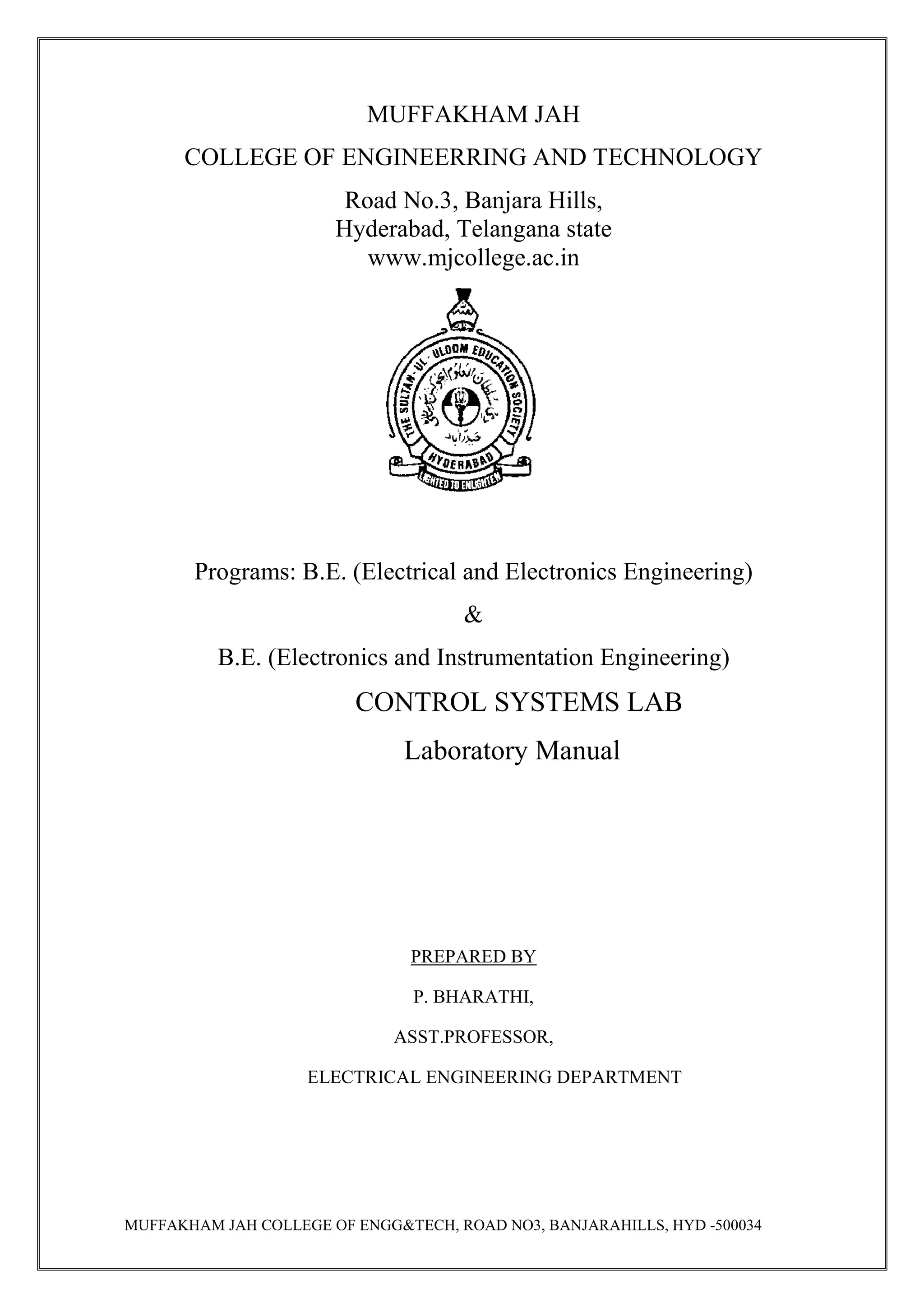
EXPERIMENT NO: 03
D.C POSITION CONTROL SYSTEM
Aim : To study D.C position control system.
Apparatus: D.C position control system unit.
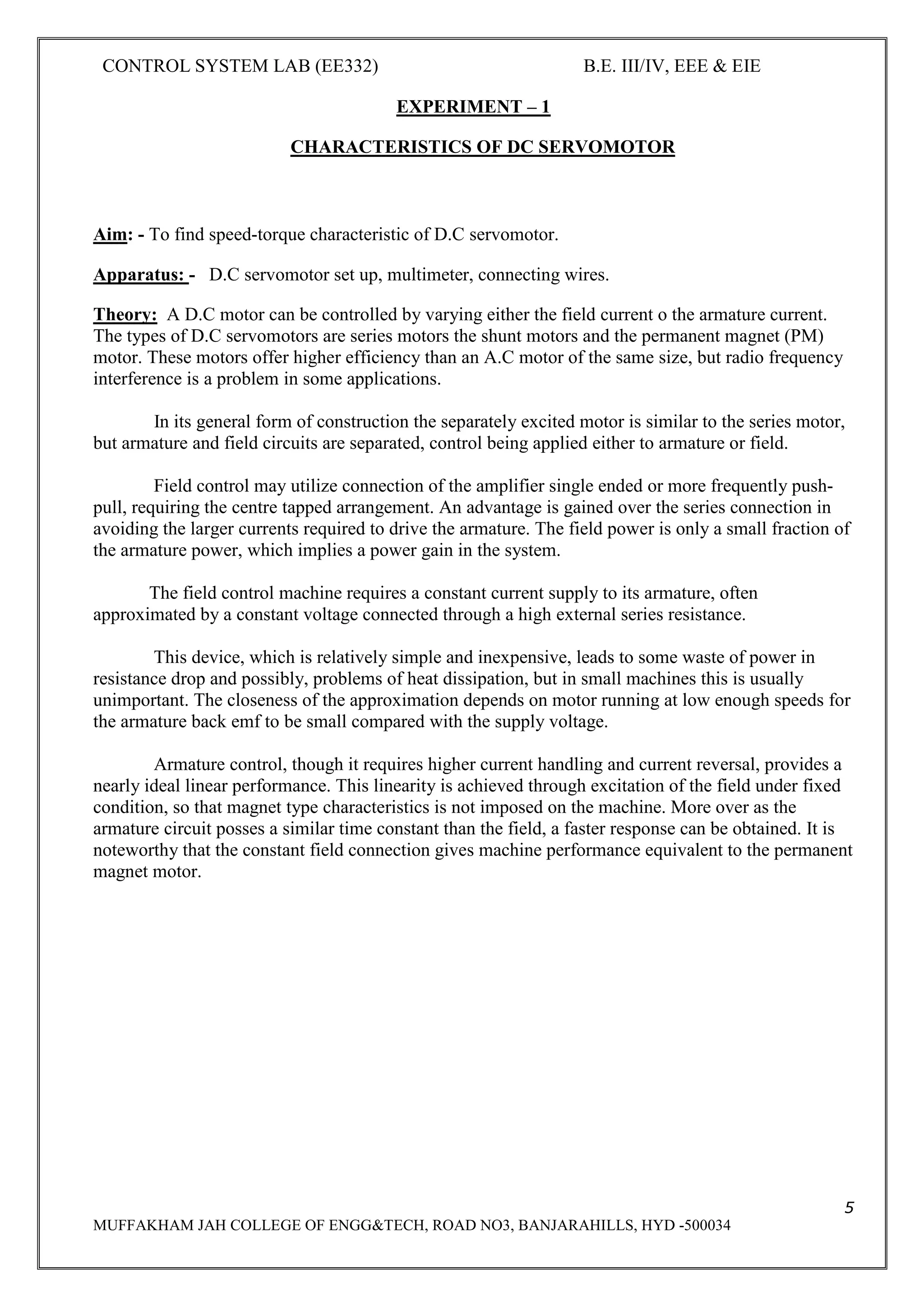
Theory:
The D.C Position control system is so called because the D.C signals exist in the system. For example
if the reference input and the controlled output are constant values a straight line can graphically
represent the actuating signal.
The signals in the other part of the system can be represented in the similar manner. For D.C voltage
controlled system, the actuating signal e [t]is a D.C voltage. In the simplest form the output position
and the reference position o1and 02 are measured and compared by a potentiometer pair whose
output voltage is proportional to error in the angular position. The error voltage is amplified and
applied to servomotor whose positions the load and the output potentiometer such that the error is
reduced to zero.
NEED FOR STABILIZATION
With switch SW1in open position and the step change in the input shaft, the output shaft exhibits an
oscillating behaviour. This happens because of the system elements, which are capable of storing
energy i.e. capacitance, inductance inertia of moving components like rotor, load, gear train etc. Once
the system is excited by change in the input signal, the various elements begin to store energy, even if
the error voltage falls to zero. The stored energy causes the output shaft to move in the same
direction. This creates an error of opposite polarity and the system is again instructed to work in the
opposite direction. In this way, energy storing elements tend to produce overshoots and undershoot in
the system. In the experimental setup, output Derivative Feedback is used for stabilization of the
output.
The Tachogenerator, which is coupled to the motor, generates an output voltage, which is
proportional to the rate of change of displacement. This voltage is coupled to the input of error
amplifier, either in the regenerative mode or degenerative mode.
By the adjustment of potentiometer P4ampunt of derivative feedback can be adjusted, while DPDT
switch is meant for selection of mode of stabilizing feedback.
HOW DERIVATIVE FEEDBACK WORKS
When switch SW1 is closed [i.e. inTACHO IN position] and the degenerative feedbacks are suitably
adjusted, we observe that the output shaft follows the input shaft in a smooth fashion without any
unwanted oscillations.](https://image.slidesharecdn.com/iiieieiisemcslabmanualee332-190622093527/75/Iii-eie-ii-sem-cs-lab-manual-ee332-12-2048.jpg)
![CONTROL SYSTEM LAB (EE332) B.E. III/IV, EEE & EIE
14
MUFFAKHAM JAH COLLEGE OF ENGG&TECH, ROAD NO3, BANJARAHILLS, HYD -500034
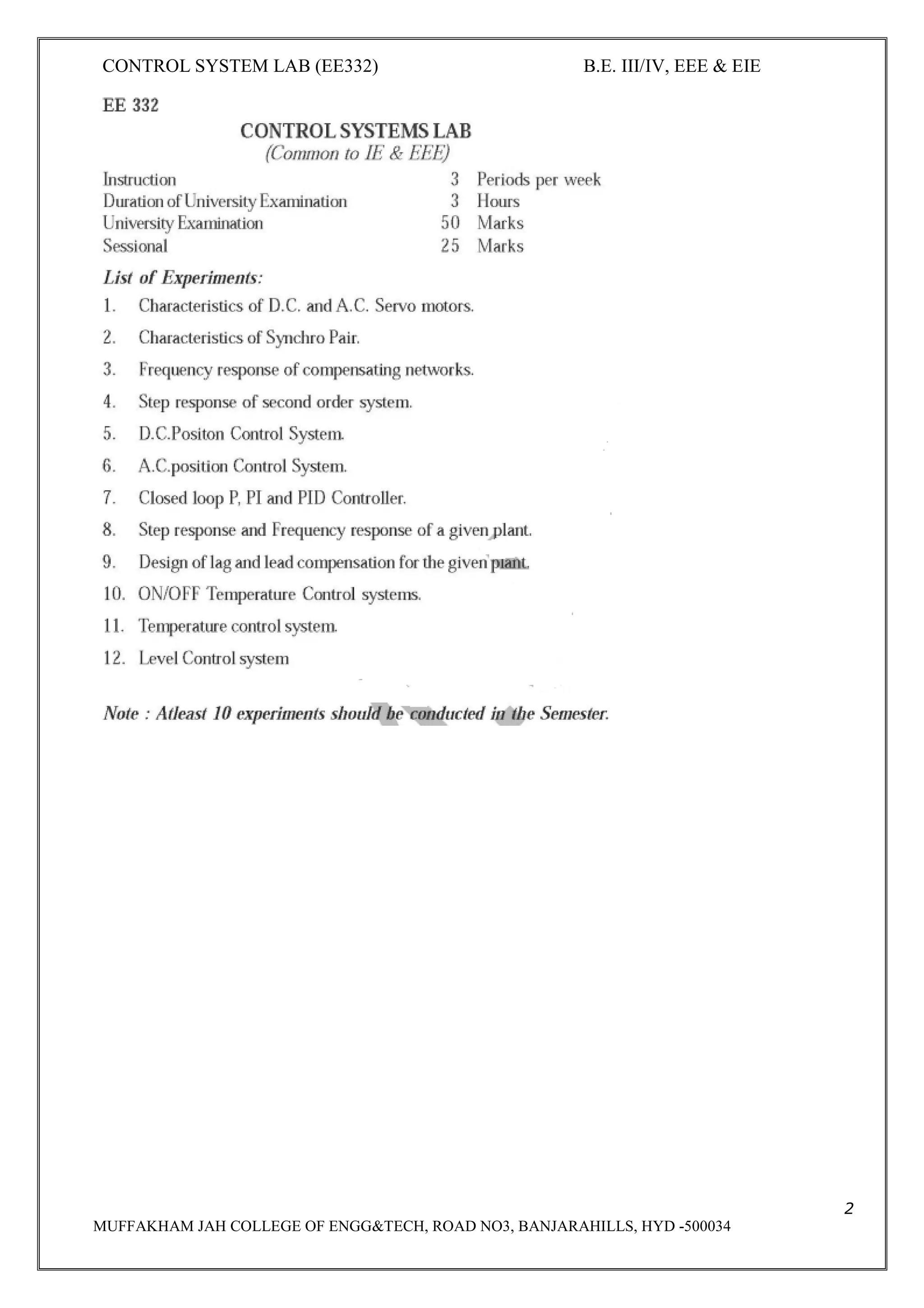
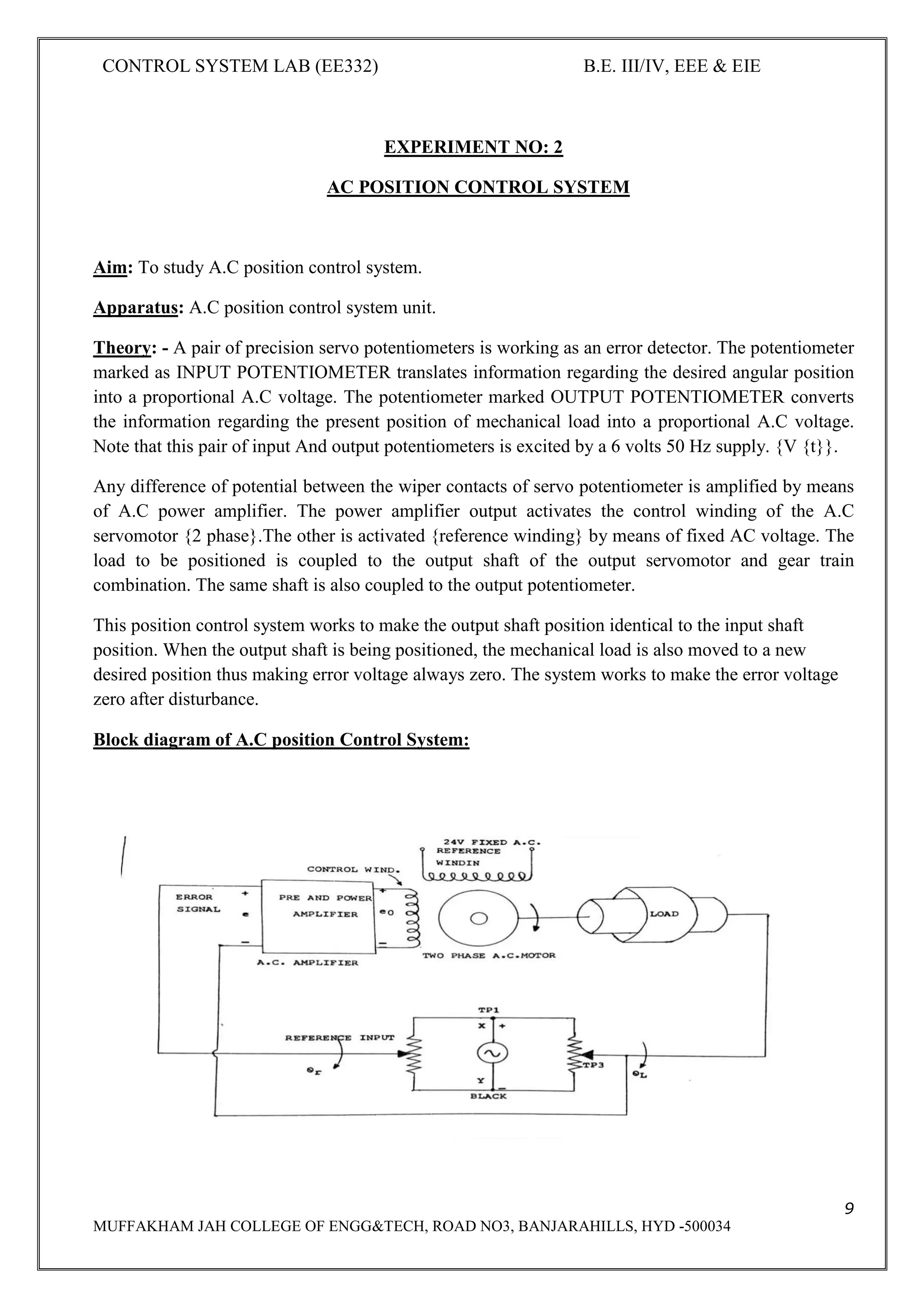
Procedure:
1. Before switching on the main panel, see that the switches SW3, SW4 {on the LHS panel} are
in the downward position i.e. ON position.
2. Ensure that SW1&SW2are in the off position i.e upward position.
3. Keep the input position P1 in 10 positions
4. Potentiometer p3 [amplifier gain adjustment] should be in mid position.
5. Now switch on the main unit LED ‘Rand LED ‘G” should glow.
Operation without feedback [SW1in off position i.e. Tacho Out}
6. Now slowly advance the i/p potentiometer P1 in clockwise direction. The o/p potentiometer
along with load will be seen to be following the change in the i/p potentiometer.
7. When the i/p is disturbed the null indicator will be showing some indication but when the o/p
reaches desired positions, again the null indicator indicates almost zero. It may be noted that when i/p
POT is moved in anti-clockwise direction, the o/p POT also moves in the reverse direction.
Step change in input
8. Now change the i/p POT in a step fashion (in fact approximating step input). The output will be
observed to change in oscillatory mode.](https://image.slidesharecdn.com/iiieieiisemcslabmanualee332-190622093527/75/Iii-eie-ii-sem-cs-lab-manual-ee332-14-2048.jpg)


![CONTROL SYSTEM LAB (EE332) B.E. III/IV, EEE & EIE
20
MUFFAKHAM JAH COLLEGE OF ENGG&TECH, ROAD NO3, BANJARAHILLS, HYD -500034
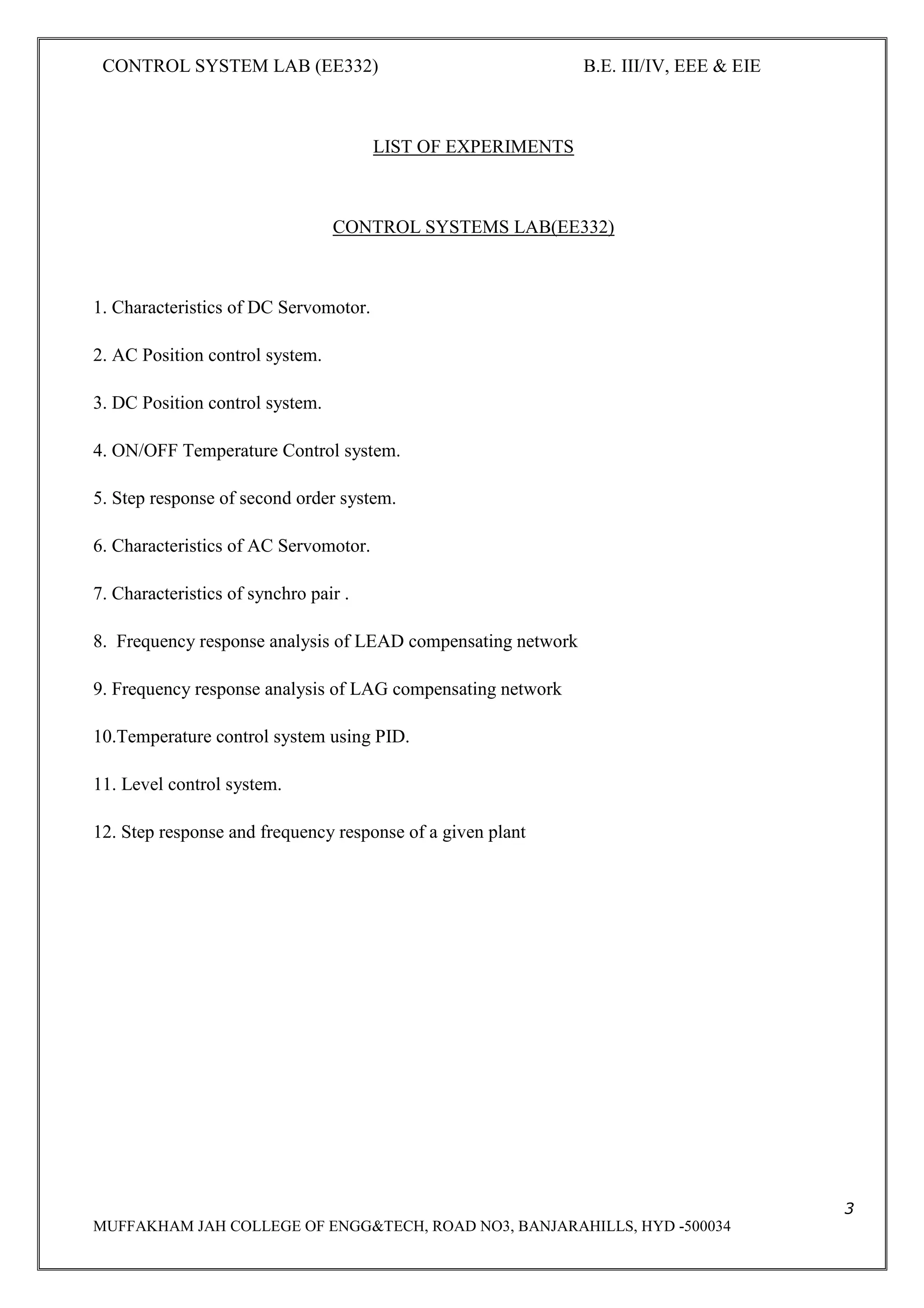
EXPERIMENT – 5
TIME DOMAIN ANALYSIS OF SECOND ORDER SYSTEM
Aim: - To perform the time domain analysis of second order system when
subjected to unit a step input.
Apparatus: Signal generator, CRO probes, bread board, Resistor, Inductor, Capacitor, connecting
wires.
Circuit diagram:
Theory: - Applying Laplace transforms to the circuit,
Vi(s) = I(s) [R+SL+1/SC]
V0(s) = I(s) . 1/SC
Transfer function
V0(s)/ Vi(s) =
=
Comparing with standard representation second order type-1 system](https://image.slidesharecdn.com/iiieieiisemcslabmanualee332-190622093527/75/Iii-eie-ii-sem-cs-lab-manual-ee332-20-2048.jpg)
![CONTROL SYSTEM LAB (EE332) B.E. III/IV, EEE & EIE
21
MUFFAKHAM JAH COLLEGE OF ENGG&TECH, ROAD NO3, BANJARAHILLS, HYD -500034
C(S)/R(S) =
=
Wn^2= 1/LC => Wn = 1/ √LC = Natural frequency
2ƐWn=R/L => Ɛ = R/2L√LC = R/2*√C/L
Damping factor = Ɛ = R/2√C/L
R(s) =1/S
C(s) = = *1/s
Applying inverse laplace transform and solving
C(t) = sin[ ]
Wd= Wn √1-Ɛ^2
Steady state value of the system
Lt C(t) = Css = 1
t->∞
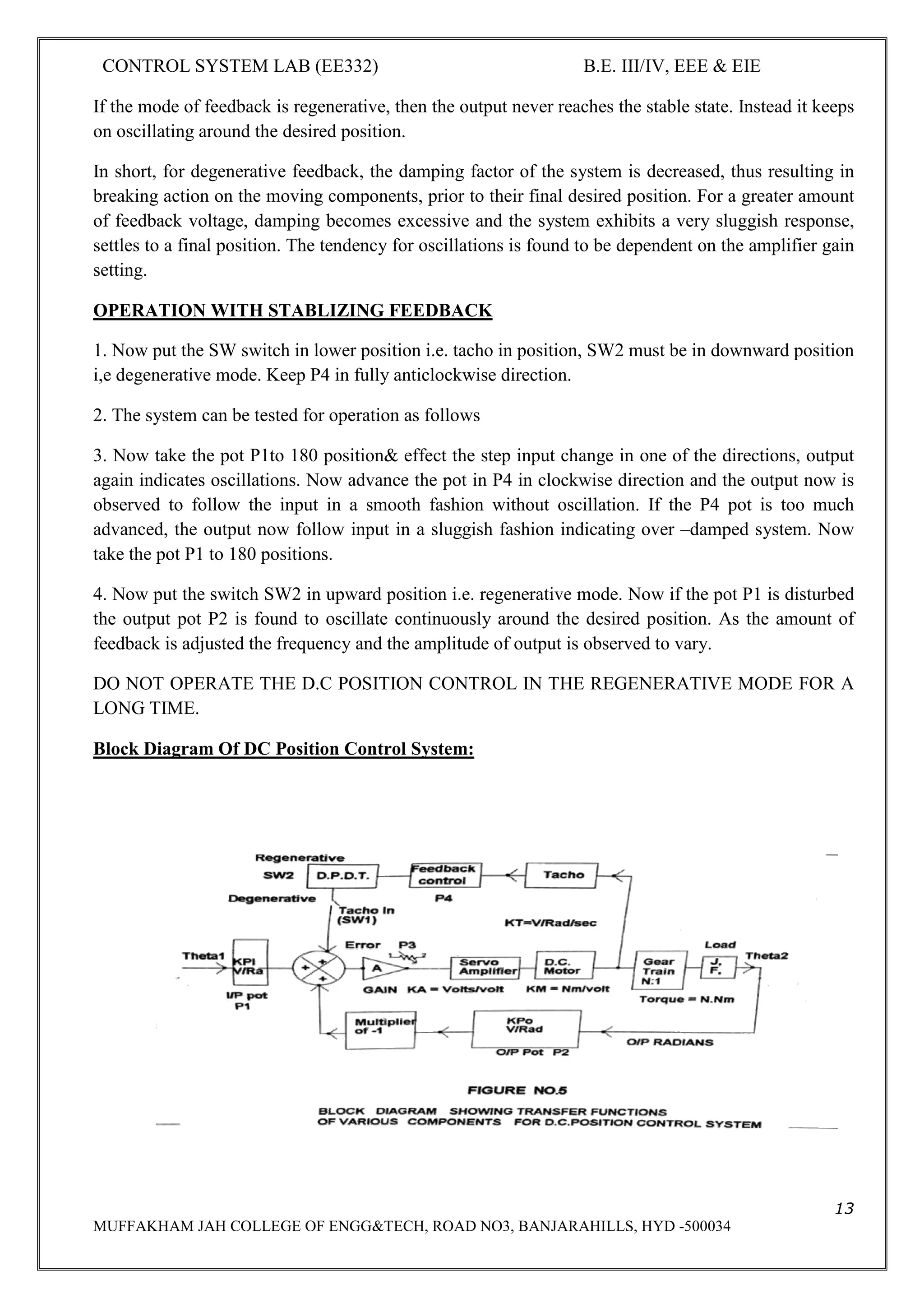
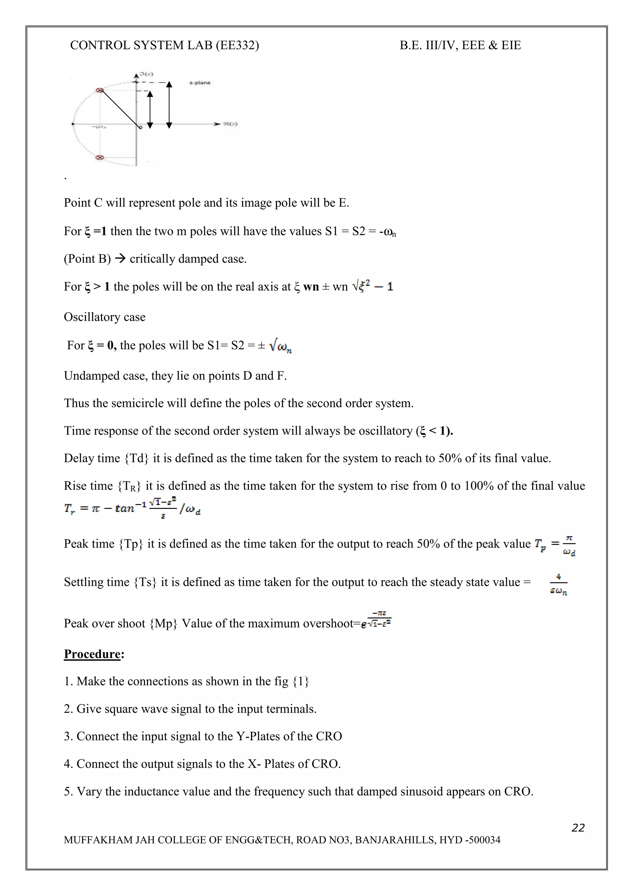
Poles of second order system
The poles S1 and S2 are
S1 = -ξ ωn + j ωn √1- ξ2
S2 = -ξ ωn - j ωn √1- ξ2
So if a semicircle of ωn is plotted in S-plane having σ as real axis and jω as imaginary axis then the
various poles will be on this semi circle as shown in the fig.](https://image.slidesharecdn.com/iiieieiisemcslabmanualee332-190622093527/75/Iii-eie-ii-sem-cs-lab-manual-ee332-21-2048.jpg)
![CONTROL SYSTEM LAB (EE332) B.E. III/IV, EEE & EIE
26
MUFFAKHAM JAH COLLEGE OF ENGG&TECH, ROAD NO3, BANJARAHILLS, HYD -500034
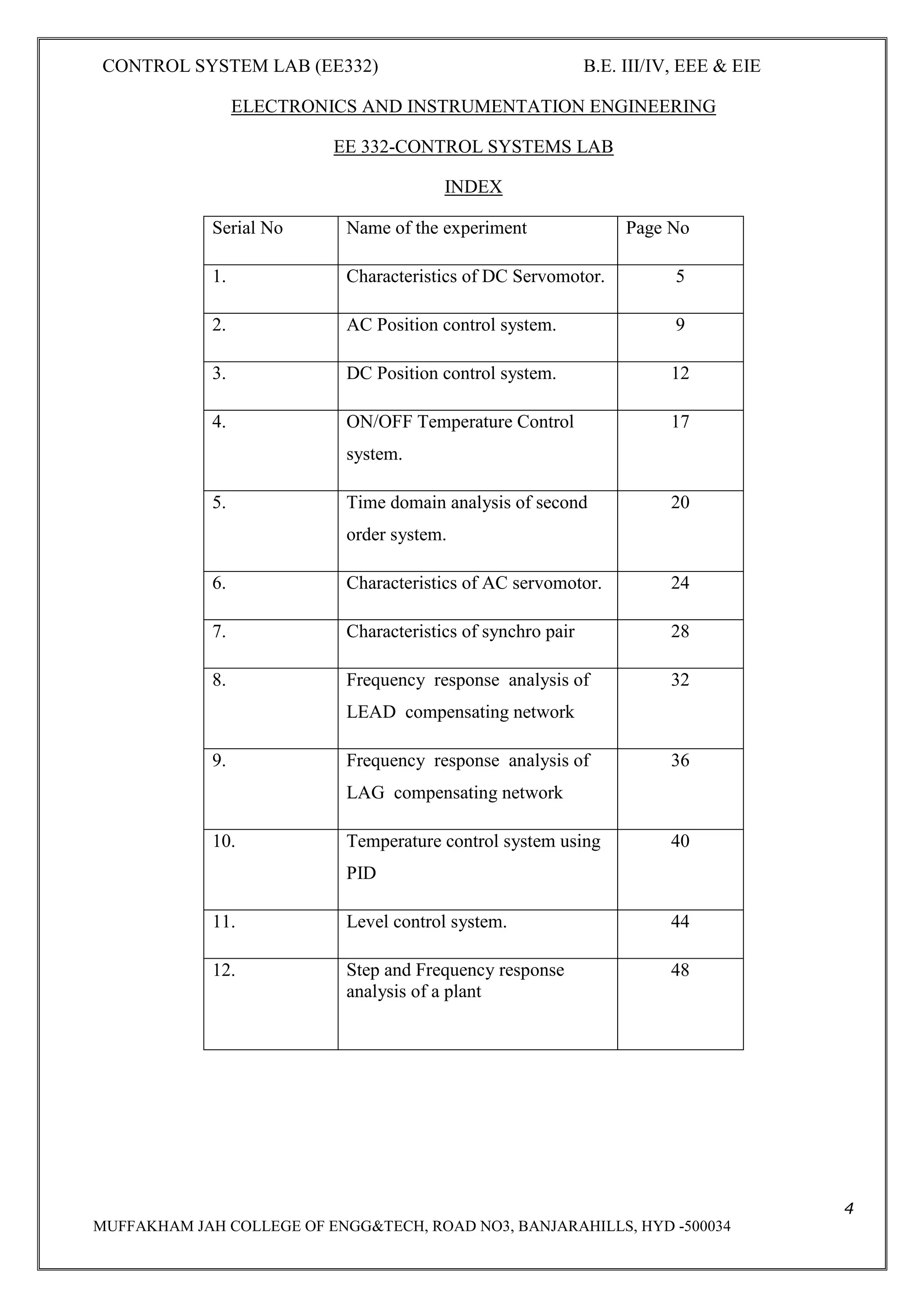
Procedure:
1. Study all the controls carefully on the front panel. Keep the switch SW3 in upward position,
indicating that the armature circuit of D.C machine is not connected to auxiliary power supply
[12v], switch SW2 should also be in off position.
2. Ensure P1 and P2 are in fully anticlockwise position.
3. Now switch on SW1 and also switch on SW2.you can observe that A.C servomotors will start
rotating and the speed will be indicated by the meter M1 on the front panel. [It is assumed that
calibration procedure is already carried out for speed measurement].
4. With SW3 in off position vary the speed of the A.C servomotor by moving P1 in clockwise
direction and note the e.m.f generated by the D.C machine[Now working as D.C generator or
tachometer].Enter the results in table 1.[Use a D.C voltmeter in the range 0to 2 volts or so].
5. Now switch SW3 in off condition, switch on SW2 and keep the pot P1 in minimum position.
You can observe that the A.C servomotor starts moving with speed being indicated by the
RPM indicated. You can measure the reference winding voltage [about 100 volts A.C] and
control winding voltage [which is variable by P1] notes the speed of A.C servomotor. Now
switch SW3 and start loading A.C servomotor by values on Ia and N. Enter this in table 2.
6. Now you may set control winding voltage to a new value of 30 volts after switching off
SW3.Again repeat the process as indicated in step No 5 i.e. table2 for a new value of control
winding voltage.
7. Plot the speed torque characteristics for various values of control winding voltages. Study
their nature.
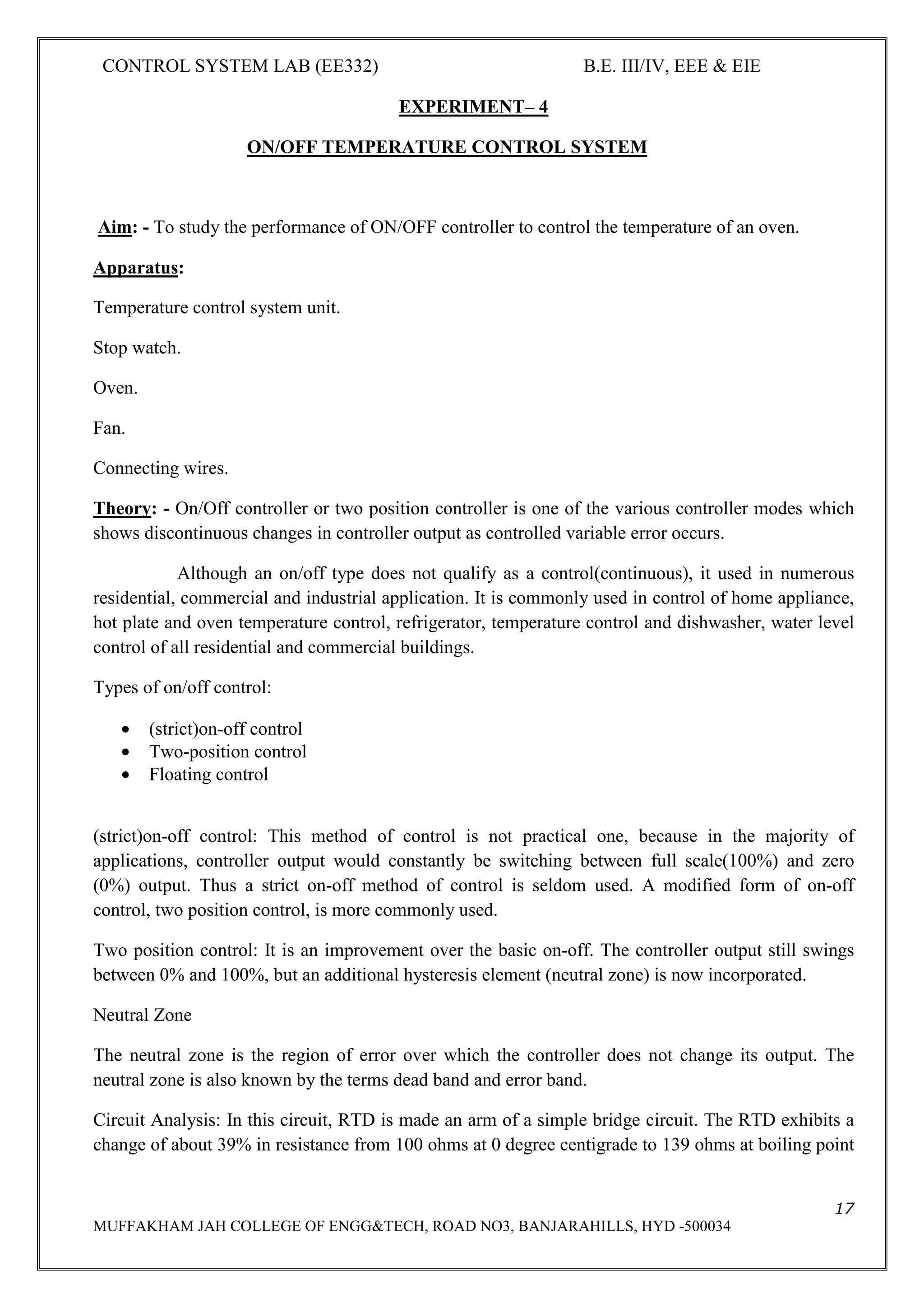
OBSERVATION:
Table No. 1
SNO RPM EB = VOLTS](https://image.slidesharecdn.com/iiieieiisemcslabmanualee332-190622093527/75/Iii-eie-ii-sem-cs-lab-manual-ee332-26-2048.jpg)
![CONTROL SYSTEM LAB (EE332) B.E. III/IV, EEE & EIE
27
MUFFAKHAM JAH COLLEGE OF ENGG&TECH, ROAD NO3, BANJARAHILLS, HYD -500034
TABLE No. 2
Expected Graphs:
Plot the speed Vs Torque characteristics of the A.C Servomotor.
PRECAUTIONS:
1. Before switch on P1 and P2 should be always brought to most anticlockwise position
Controls P1and P2 should be operated in gentle fashion.
Result: The speed-torque characteristics of A.C Servomotor are studied
SNO Ia[Ma] N[RPM] Eb[Volts} P=Eb*Ia[mW] Torque[T]=p*1.019*10*60/2](https://image.slidesharecdn.com/iiieieiisemcslabmanualee332-190622093527/75/Iii-eie-ii-sem-cs-lab-manual-ee332-27-2048.jpg)
![CONTROL SYSTEM LAB (EE332) B.E. III/IV, EEE & EIE
28
MUFFAKHAM JAH COLLEGE OF ENGG&TECH, ROAD NO3, BANJARAHILLS, HYD -500034
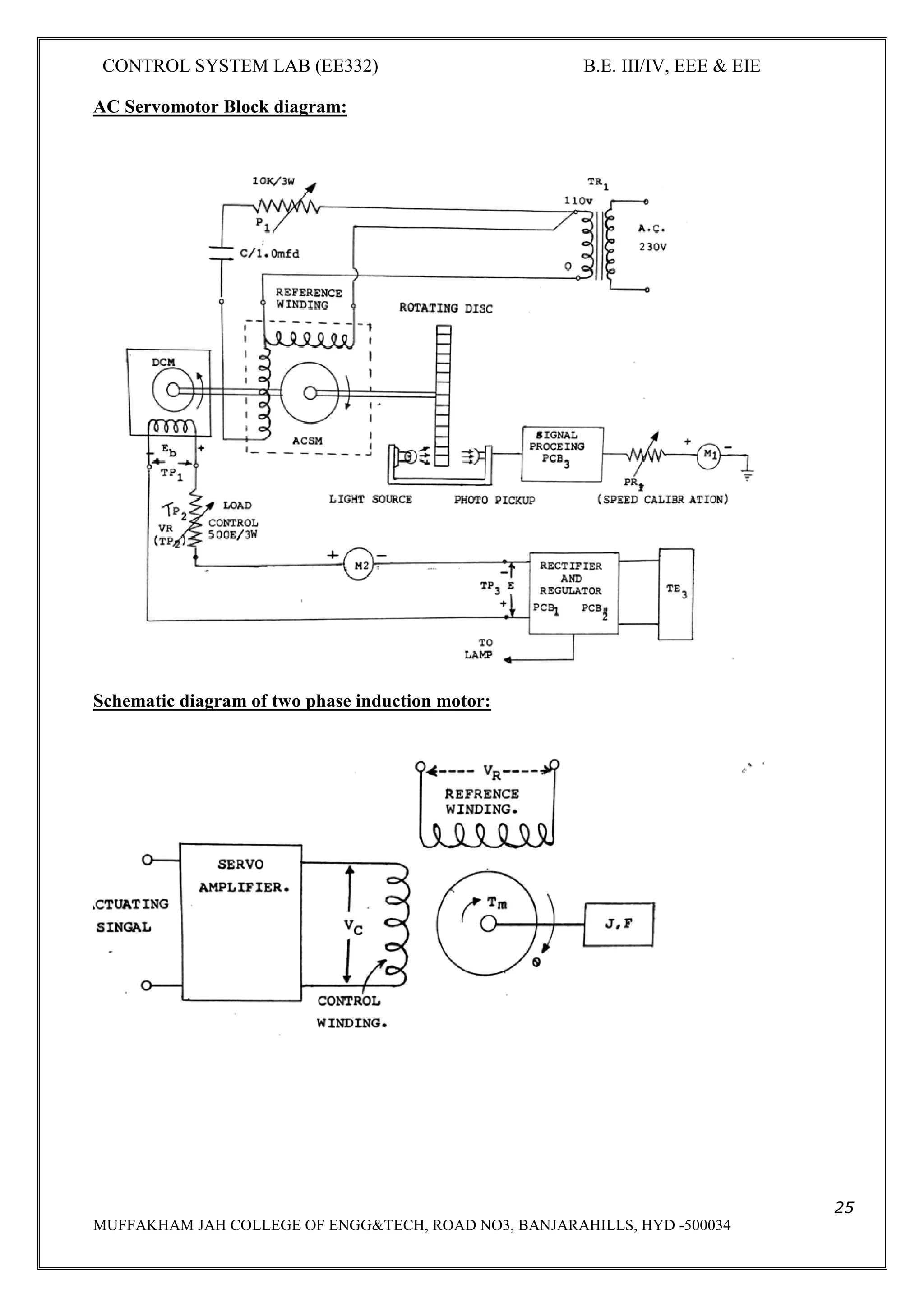
EXPERIMENT – 7
CHARACTERISTICS OF SNCHRO PAIR
Aim: - To study the properties of synchro
Apparatus : Synchro setup, Digital Multimeter, Connecting wires
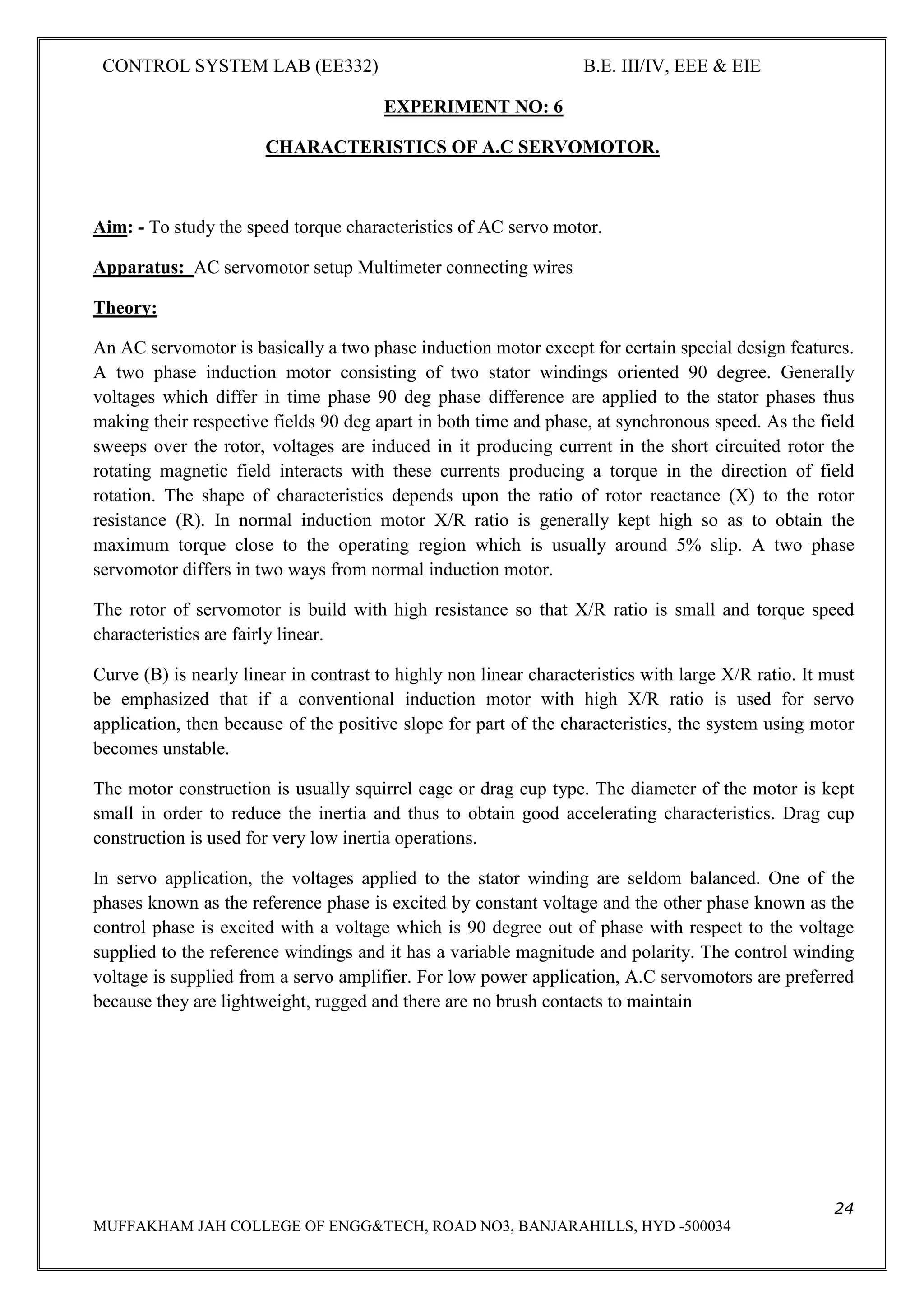
Theory: A synchro is an electromagnetic transducer commonly used to convert an angular position
of a shaft into an electrical signal. The basic synchro is called synchro transmitter. Its construction is
similar to that of three phase alternator. Let an A.C voltage Vr(t)=
Vr sinwct (1)be applied to the rotor of the synchro transmitter. This voltage causes a flow of
magnetizing current in the rotor coil which produces a the air gap along the stator periphery. Because
of transformer action, voltages are induced in each of the stator coils. As the air gap flux is sinusoid
ally distributed, the linking any stator coil is proportional to the cosine of the angle between rotor and
stator coil axis. Let Vs1n, Vs2n,Vs3n respectively be the voltages induced in the stator coils S1,S2,S3
with respect to the neutral.
Then with respect to the rotor position as shown in the fig[rotor makes an angle degrees with stator
S2]
Vs1n= Kvr Sin wct cos [ +120] …..(2)
Vs2n= Kvr Sin wct cos ( ……… (3)
Vs3n= Kvr Sin wct cos [ +240] …..(4)
Three terminal voltages of the stator are
Vs1s2= Vs1n-Vs2n
=3 KVr sin ( +240)sin wct….(5)
Vs2s3= Vs2n-Vs3n
=3 kvr sin ( +120)sin wct…..(6)
Vs3s1= Vs3n-Vs1n
=3 kvr sin ( )sin wct……….(7)](https://image.slidesharecdn.com/iiieieiisemcslabmanualee332-190622093527/75/Iii-eie-ii-sem-cs-lab-manual-ee332-28-2048.jpg)
![CONTROL SYSTEM LAB (EE332) B.E. III/IV, EEE & EIE
29
MUFFAKHAM JAH COLLEGE OF ENGG&TECH, ROAD NO3, BANJARAHILLS, HYD -500034
When =0 from equations 2 &3 it is seen that maximum voltage is induced in the stator coils S2
while it follows from equation [ 7 ] that the terminal voltage Vs3s1 is zero. The position of the rotor
is defined as ELECTRICAL ZERO.POSITION.
Schematic diagram of synchro transmitter](https://image.slidesharecdn.com/iiieieiisemcslabmanualee332-190622093527/75/Iii-eie-ii-sem-cs-lab-manual-ee332-29-2048.jpg)

![CONTROL SYSTEM LAB (EE332) B.E. III/IV, EEE & EIE
32
MUFFAKHAM JAH COLLEGE OF ENGG&TECH, ROAD NO3, BANJARAHILLS, HYD -500034
EXPERIMENT– 8
FREQUENCY RESPONSE ANALAYSIS OF LEAD
COMPENSATINGNETWORK
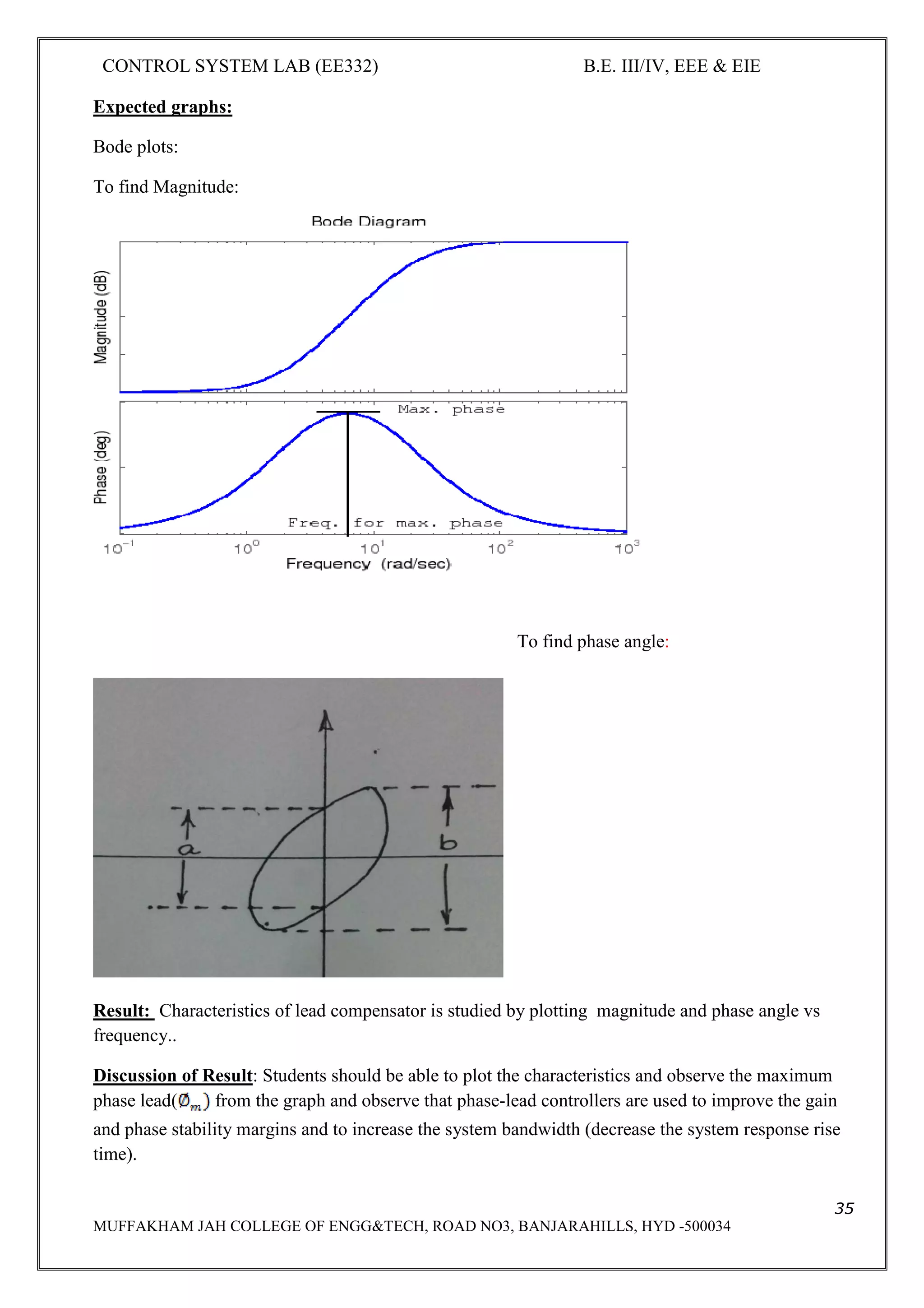
Aim: - To Plot Magnitude and Phase angle characteristics versus Frequency of LEAD compensator.
Apparatus : - Signal generator, CRO, breadboard, connecting wire, CRO probes.
Theory: In Control systems, Compensating Networks are used to improve the Performance of the
systems and to meet some performance specifications. They are usually connected in series with the
original systems.
Circuit Diagram and Transfer functions:
, C= 33KF, R2= 1KΩ
Step1: Apply L.T to the network and simplifying parallel combination of R1 and 1/CS
= R1*1/CS
R1+1/CS
= R1
R1CS+1
Step2: Analysis applying KVL to loop
Vi(s) = I(s) [ + ]
Vi(s) = I(s) [ ]
As Vo(s) = I(s)* R2](https://image.slidesharecdn.com/iiieieiisemcslabmanualee332-190622093527/75/Iii-eie-ii-sem-cs-lab-manual-ee332-32-2048.jpg)

![CONTROL SYSTEM LAB (EE332) B.E. III/IV, EEE & EIE
36
MUFFAKHAM JAH COLLEGE OF ENGG&TECH, ROAD NO3, BANJARAHILLS, HYD -500034
EXPERIMENT – 9
FREQUENCY RESPONSE ANALYSIS OF LAG COMPENSATING
NETWORK
Aim: To plot Magnitude and Phase angle characteristics versus frequency of LAG
COMPENSATOR.
Theory:
In Control Systems, Compensating Networks are used to improve the performance of the
system and to meet some performance specifications. They are usually connected in series
with the original system.
CIRCUIT DIAGRAM AND TRANSFER FREQUENCY
Vi= input from signal generator , Vo= output
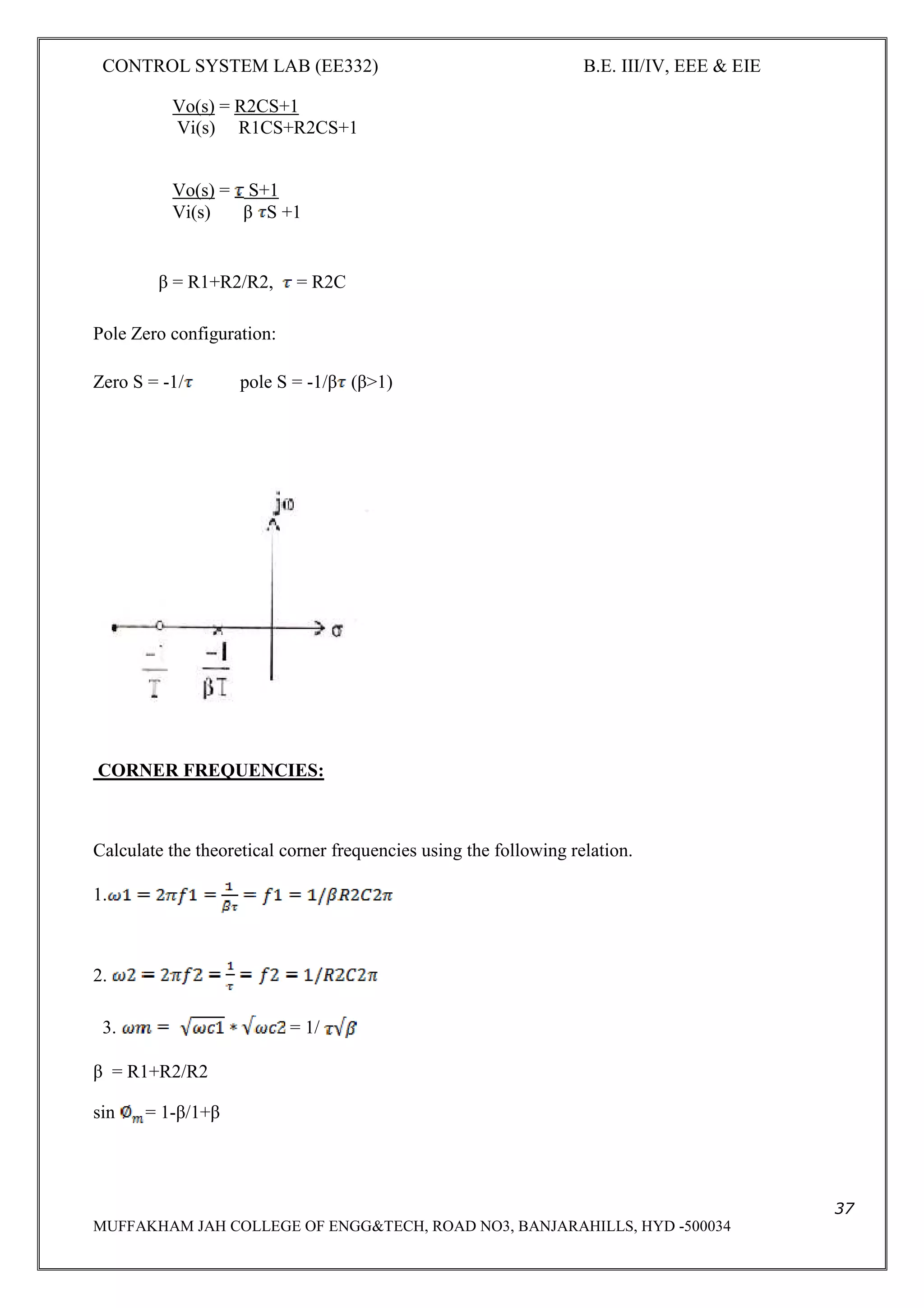
Transfer Function:
Step1: Applying laplace transform to the network
Vo= I(s) [R2CS+ 1/CS]
Step2: Applying KVL
Vi(s) = I(s) [R1+ R2CS+1/Cs]
Vi(s) = I(s) [R1CS+R2CS+1/Cs]
Vo(s) = I(s) [R2CS+1/CS]](https://image.slidesharecdn.com/iiieieiisemcslabmanualee332-190622093527/75/Iii-eie-ii-sem-cs-lab-manual-ee332-36-2048.jpg)


![CONTROL SYSTEM LAB (EE332) B.E. III/IV, EEE & EIE
44
MUFFAKHAM JAH COLLEGE OF ENGG&TECH, ROAD NO3, BANJARAHILLS, HYD -500034
EXPERIMENT-11
LEVEL CONTROL SYSTEM
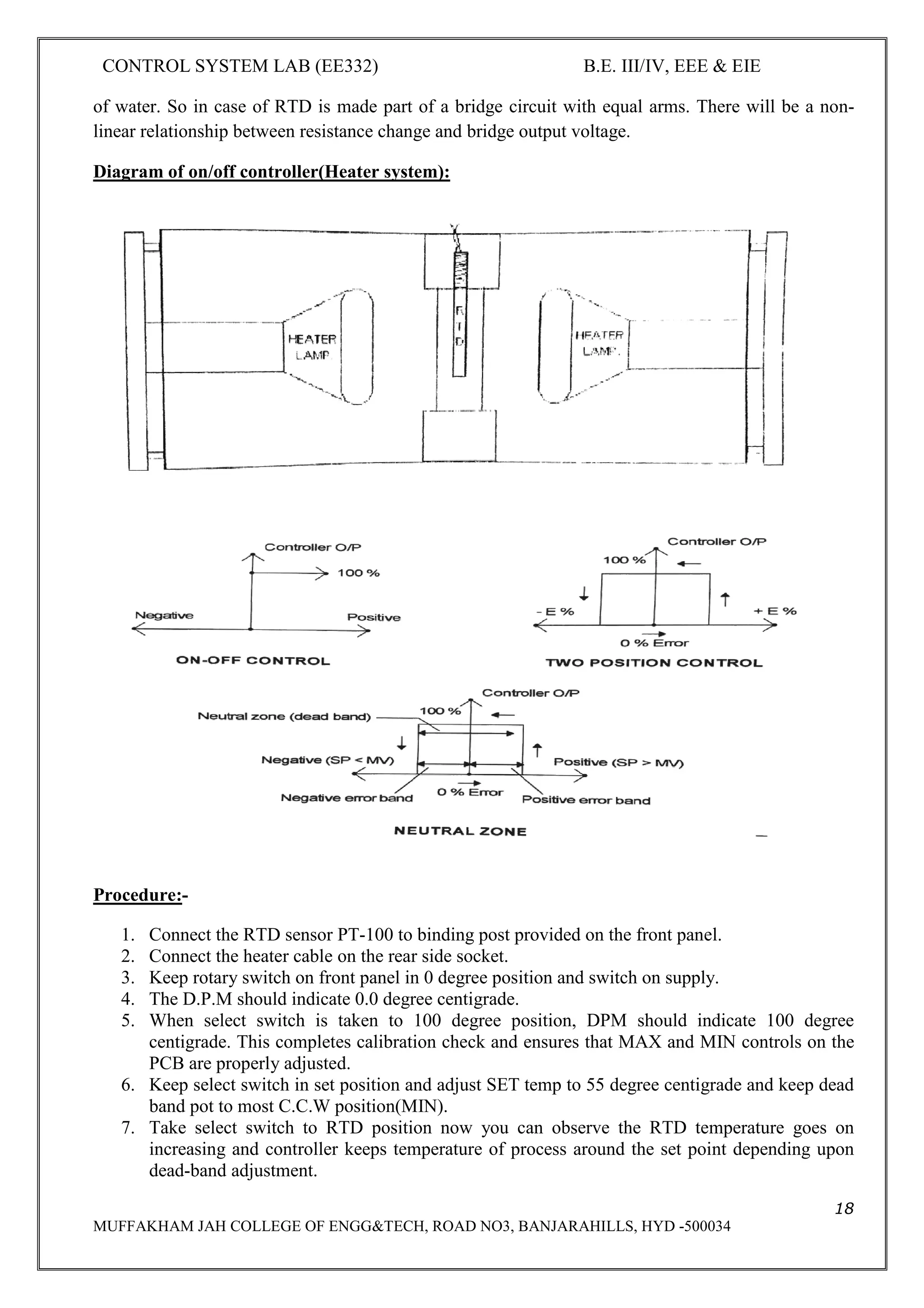
Aim: To study the on-off, P, P+I, P+I+D based level control system.
Apparatus: Level control trainer
Theory:-
ON –OFF CONTROL
In automatic controlled process the parameters to be controlled is measured with the set point by
process controller. The difference between the measured signal and the set point is error . the
controller performs on-line calculations based on error and other setting parameters and generates an
output signal. The output signal drives the final control elements like control valves or a damper to
control the process to the set point.
A special case of proportional control is On-off control. If the proportional band of the controller is
made very low (=0) the controller output will move from one extreme position to other for slight
deviation of process value from the set point. This very sensitive action is called On-off control
because final control element is either open (on) or close (off) i.e. operates like a switch. There are
the simplest controllers.
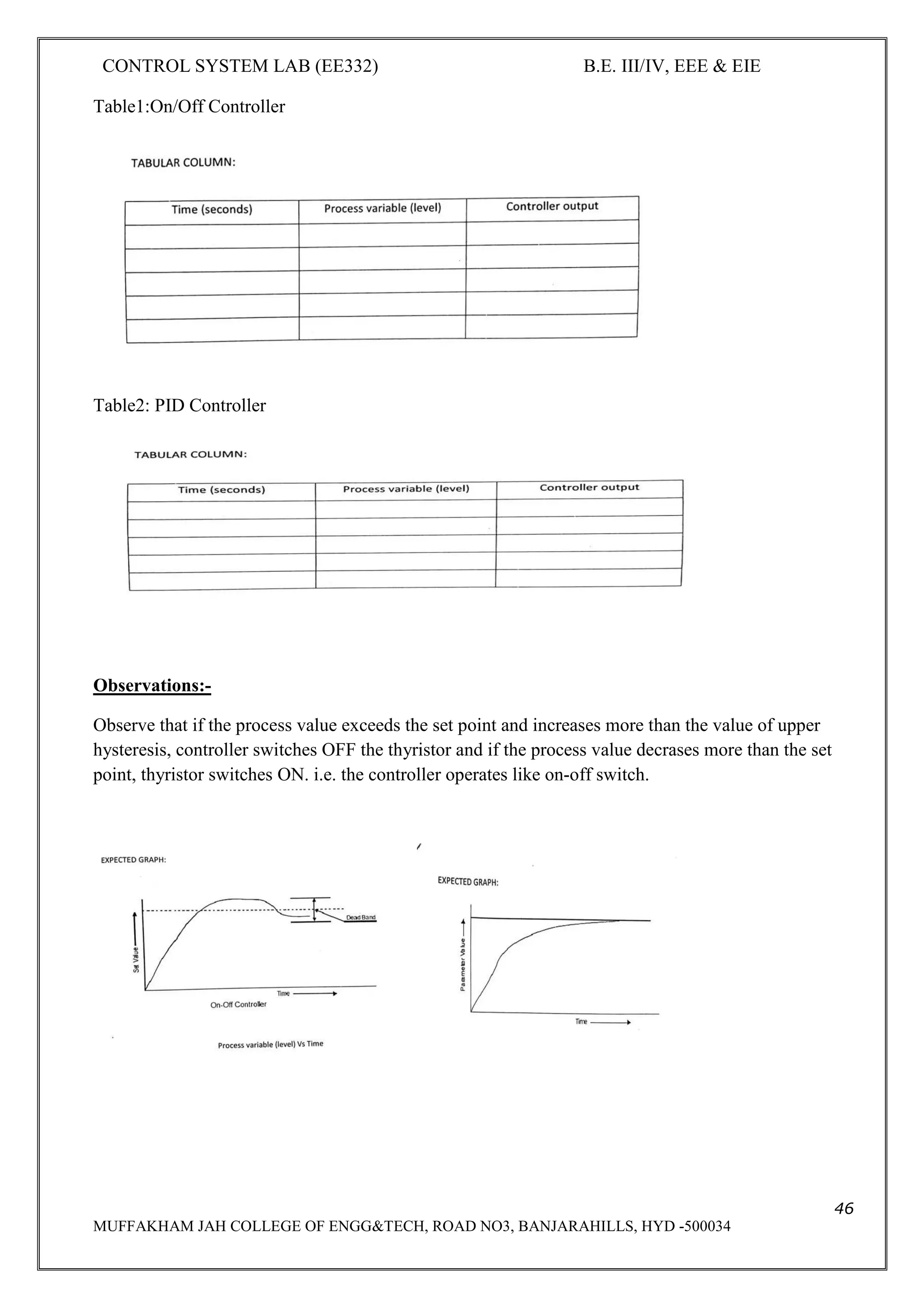
Hysteresis is a value set in the vicinity of on-off operating point. Upper hysteresis is value or band in
which process value is allowed to operate above the set point and lower hysteresis is valve or band in
which process value is allowed to operate below the set point.
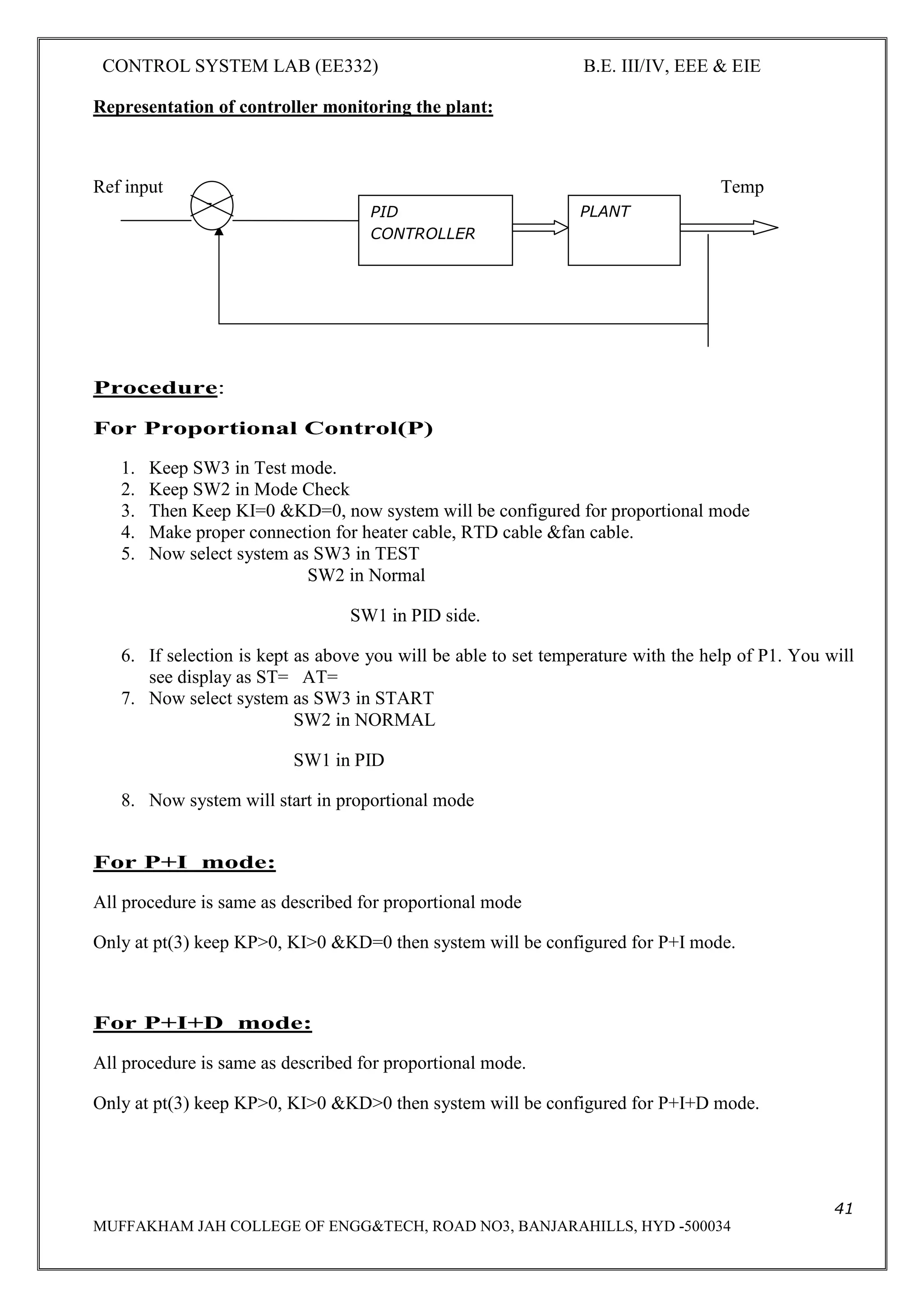
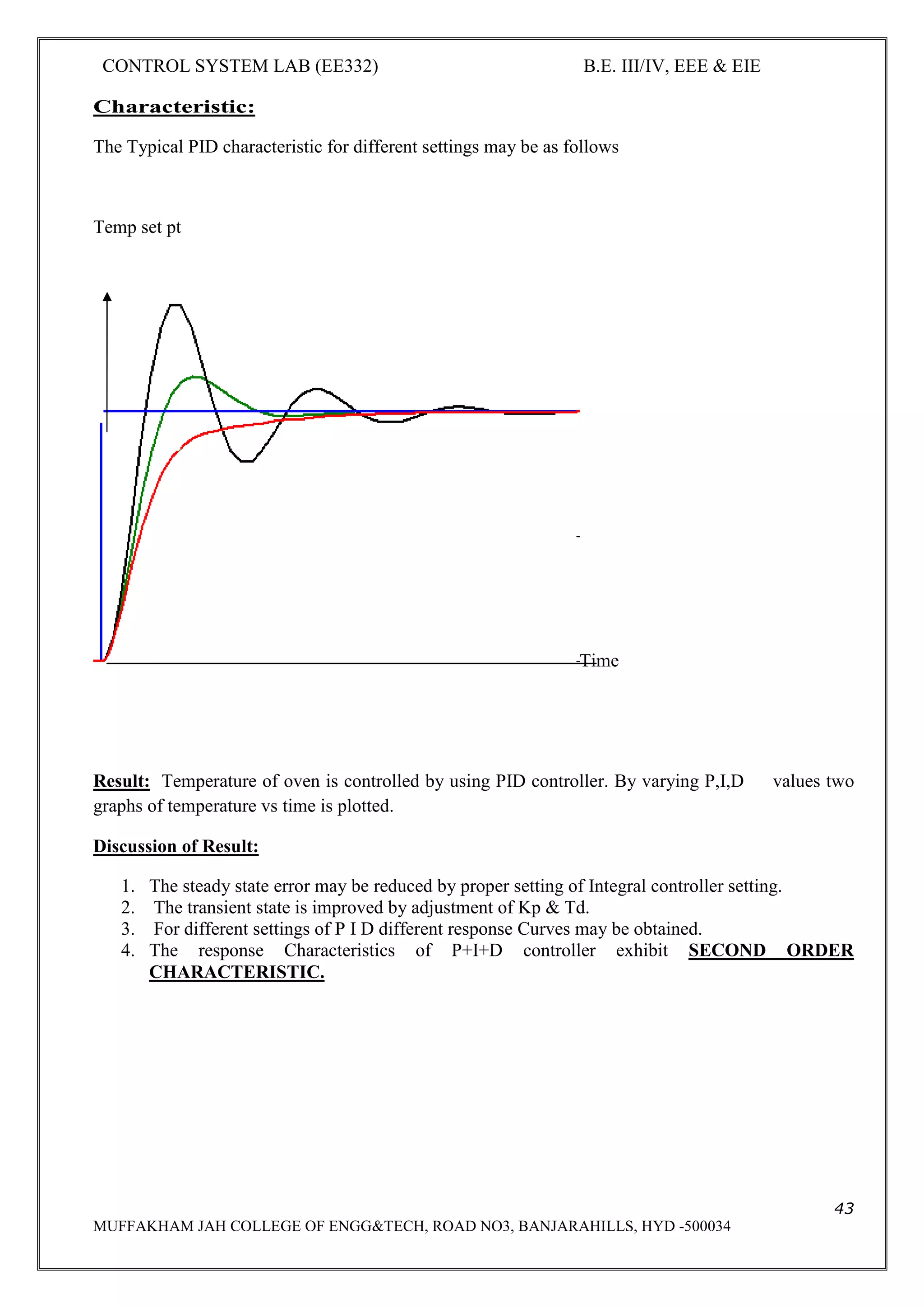
Proportional-integral-derivative (PID) controllers
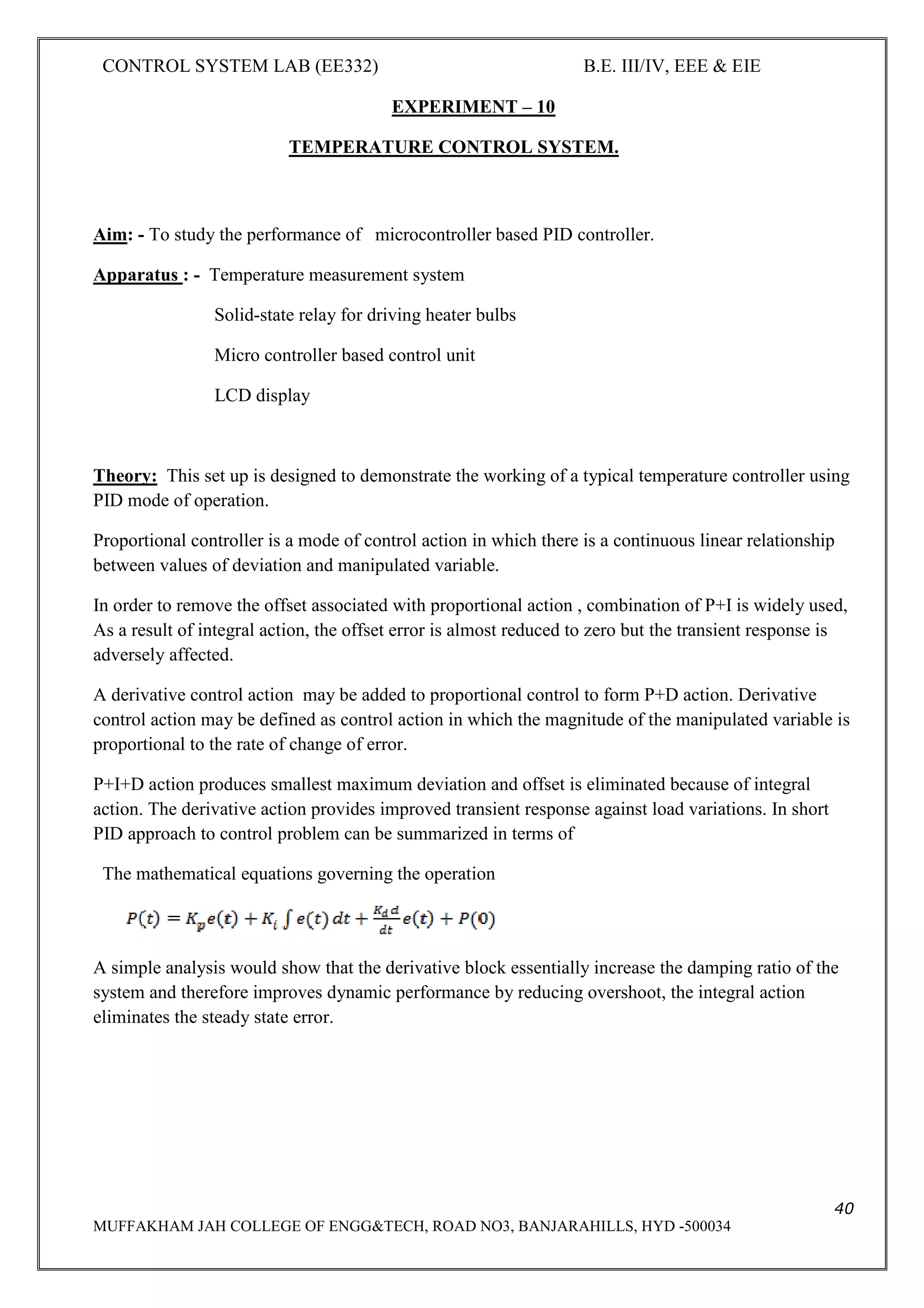
The three-mode controllers (PID) are the most common feedback controller used in industrial control.
PID controllers are used for controlling almost all process variables like temperature, flow, level,
pressure, etc. in a continuous or bath process. The output of a PID controller is given by:
Op= b+100/pb [e+1/ti .dt+td.de/dt]](https://image.slidesharecdn.com/iiieieiisemcslabmanualee332-190622093527/75/Iii-eie-ii-sem-cs-lab-manual-ee332-44-2048.jpg)


- The document describes an experiment to study an AC position control system. It uses a pair of servo potentiometers as an error detector to compare the desired input position to the actual output position. - Any difference in position creates an error voltage that is amplified and used to drive a 2-phase AC servomotor. The servomotor moves the output shaft and mechanical load to reduce the position error to zero. - The experiment involves setting the input position at various angles and observing the output position with different amplifier gains. Higher gain results in smaller position error as it more quickly drives the servomotor to match the input position.


![[8] implementation of pmsm servo drive using digital signal processing](https://cdn.slidesharecdn.com/ss_thumbnails/8implementationofpmsmservodriveusingdigitalsignalprocessing-200723180820-thumbnail.jpg?width=640&height=640&fit=bounds)


