This paper presents an improved user-centric non-orthogonal multiple access (NOMA) communication system utilizing in-band full duplex (IBFD) technology in a two-base station network. The authors derive and analyze the achievable rates of the proposed system, demonstrating a 64% improvement in total achievable rate compared to traditional systems under similar power constraints. The study emphasizes the potential of NOMA for enhancing spectral efficiency and supporting diverse traffic in upcoming 5G networks.
![TELKOMNIKA, Vol.17, No.5, October 2019, pp.2169~2178
ISSN: 1693-6930, accredited First Grade by Kemenristekdikti, Decree No: 21/E/KPT/2018
DOI: 10.12928/TELKOMNIKA.v17i5.12803 ◼ 2169
Received October 30, 2018; Revised April 3, 2019; Accepted May 1, 2019
Full-duplex user-centric communication using
non-orthogonal multiple access
Sock Theng Ooi*1
, Razali Ngah2
, Marwan Hadri Azmi3
Wireless Communication Centre, School of Electrical Engineering,
Faculty of Engineering, Universiti Teknologi Malaysia, Malaysia
*Corresponding author, e-mail: socktheng81@gmail.com1
, razalin@fke.utm.my2
, hadri@fke.utm.my3
Abstract
This paper proposes an improved user-centric Non-Orthogonal Multiple Access (NOMA)
communication in two-base station networks with in-band full duplex (IBFD) user. We derive
the achievable rates of the proposed user-centric NOMA systems. For benchmarking purposes, we also
derive the achievable rate for the user-centric system deploying conventional NOMA schemes, Orthogonal
Multiple Access (OMA) schemes and point-point communication systems. We then analyze and simulate
the performance of the proposed and all the benchmarked systems. We found that our proposed
user-centric NOMA approach has a 64% improvement in the total achievable rate when compared to
the benchmarked approach under similar power constraint.
Keywords: achievable rates, in-band fullduplex (IBFD), non-orthogonal multiple access (NOMA),
successive interference cancellation (SIC), user-centric network (UCN)
Copyright © 2019 Universitas Ahmad Dahlan. All rights reserved.
1. Introduction
Over the last few years, wireless terminals are equipped with a more advanced function
as transmitter and receiver, e.g., base stations, relays, or mobiles, due the advancement of
the modern wireless communication systems [1]. With these unique and advanced features
possess by the wireless terminals, it drives the quest for the use of in-band full duplex (IBFD)
wireless transceivers. Conventionally, the terminal operates using half-duplex modes, where it
can only transmit or receive at one time. Therefore, with the IBFD, the wireless terminals are
able to transmit and receive simultaneously over the same frequency band. This new full-duplex
capability provides a promising potential that can lead to a two-fold spectral efficiency gain [2].
The fifth generation (5G) mobile system is expected to be deployed widely in the near
future [3]. Stronger multiple access (MA) schemes have been identified as one of the key
techniques to support large-scale heterogeneous traffic and users in the upcoming 5G systems.
In recent years, non-orthogonal multiple access (NOMA) have gained a lot of research interest
due to its promising capabilities to achieve higher spectrum efficiency, and to support massive
connectivity [4-13]. Unlike the conventional multiple access that are based on the orthogonality
of the resources in either time, code or frequency domains (i.e. TDMA, CDMA, OFDMA), NOMA
has been shown to accommodate more users by allocating them on the non-orthogonal
resource, which consequently attain high spectrally efficient radio access and network
capacity [14-16]. Power domain (PD) NOMA schemes result in non-orthogonality among users,
where multiple users share the same frequency resources simultaneously by utilizing
superposition coding at the transmitter and successive interference cancellation (SIC) at
the receiver [17, 18]. Although NOMA has recognized as a promising multiple access technique
for 5G but most of the researchers have focused on downlink traffic only [19, 20]. Uplink traffic
begins to attract the attention since the emergence of new mobile and Internet-of-Things (IoT)
applications. Uplink traffic plays a significant role when the IoT experiences massive growth,
which incur intensive uplink traffic by sensing and monitoring characteristic [21].
Apart from a more advanced IBFD capability and stronger MA schemes, user-centric
network (UCN) has also been identified to become new key enabler for 5G networks to provide
ubiquitous high-speed connectivity to mobile users. Traditional cell-centric networks construct
the network, where each handset communicates with only one specific cell site at a time. Under
UCN architecture, multiple cell sites that located around the mobile user are cooperating to](https://image.slidesharecdn.com/512803-200813062740/85/Full-duplex-user-centric-communication-using-non-orthogonal-multiple-access-1-320.jpg)
![◼ ISSN: 1693-6930
TELKOMNIKA Vol. 17, No. 5, October 2019: 2169-2178
2170
provide high data rates to the users in every transmission, letting the mobile user to experience
like the networks is always following it. Furthermore, UCN could intelligently recognize
the mobile user’s wireless communication and then can flexibly organize the required cell group
and resource to serve the mobile users [22-25]. In [20], a local anchor based dual connectivity is
proposed for UCN as it showed that the average user spectrum efficiency achieves an increase
of 5% gains over the current LTE system while providing seamless coverage and borderless
service to a mobile user. In another set of works, there are also studies in both traffics using
coordinating multiple points (CoMP) approach with IBFD in 5G [1, 24].
Motivated by the challenging requirements of 5G systems to provide high-speed
connectivity, this paper proposes a new user-centric NOMA communication in two-base station
networks with IBFD user. The achievable rates of the proposed system are derived. We then
analyze and simulate the performance of the system, and compared it with the performances of
state-of-the art orthogonal multiple access (OMA) and point-point communication systems.
The rest of the paper is organized as follows. In section 2, we present the system model for
the proposed user-centric NOMA scheme and all benchmarked systems. Section 3 then derives
the theoretical achievable rate for all studied and benchmarked schemes in this work. Section 4
presents and discusses the simulation results in terms of the achievable rate attained by all
schemes. Finally, the conclusions are presented in section 5.
2. System Model
Consider a user centric architecture in which two base stations, 𝐵𝑆𝑖 for i∈{1,2,u} are
supporting a user cooperatively using non-orthogonal multiple access (NOMA) schemes. Each
base station has it owns independent messages to be forwarded to the user. The studied
network topology consisting these three nodes is illustrated in Figure 1, where the distance
between the two base stations is normalized to one. The user is located in a straight line
between the two base stations with the distance of d1 from BS1. All the nodes in the considered
scenario are equipped with a single antenna. The channel modeling used in this paper is
described as follows. The channel gain between node i and node j is modeled as 𝛾𝑖𝑗 =
1
𝐿 𝑖𝑗
,
where 𝐿𝑖𝑗 = 𝑑𝑖𝑗
𝛼
denotes the path loss, 𝑑𝑖𝑗 is the distance between node i and node j, and α is
the path loss exponent parameter. Using subscripts 1, 2 and u to denote the 𝐵𝑆1, 𝐵𝑆2 and
the user node, respectively, the channel gains for all the links in Figure 1 are
𝛾1𝑢 = 𝛾 𝑢1 =
1
𝑑1𝑢
𝛼 =
1
𝑑 𝑢1
𝛼 , 𝛾12 = 𝛾21 = 1, 𝛾2𝑢 = 𝛾 𝑢2 =
1
𝑑2𝑢
𝛼 =
1
𝑑 𝑢2
𝛼.
Figure 1. Effects of selecting different switching under dynamic condition
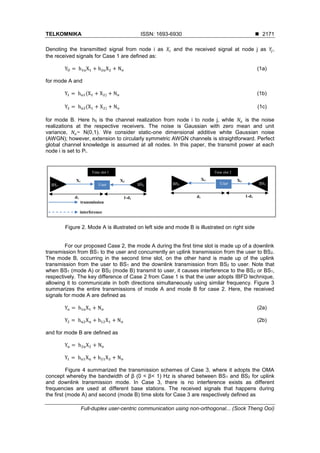
In this work, two NOMA schemes are developed, named case 1 and case 2 schemes.
Case 1 is the conventional NOMA schemes that consist of mode A and mode B, as in Figure 2.
Mode A is a downlink transmission whereby the user receives two distinct messages from both
base stations during first time slot. Mode B is the uplink transmission, which occurs in
the second time slot to concurrently forward distinct messages from user to both base stations.](https://image.slidesharecdn.com/512803-200813062740/85/Full-duplex-user-centric-communication-using-non-orthogonal-multiple-access-2-320.jpg)


![TELKOMNIKA ISSN: 1693-6930 ◼
Full-duplex user-centric communication using non-orthogonal... (Sock Theng Ooi)
2177
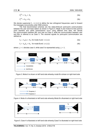
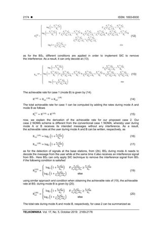
Finally, Figure 8 presents the total achievable rates of 𝑅(1)
, 𝑅(2)
, 𝑅(3)
, 𝑅(4)
and 𝑅(5)
for
every case 1, 2, 3, 4 and 5, respectively. We can see that NOMA with IBFD user improves
the performance at about 54 percentage when compared to OMA, hand-off point-to-point
communication at d1=0.5. This indicates the superiority of our proposed case 2 specially to
improve the achievable rates at the cell boundries.
Figure 8. The total achievable rates
5. Conclusion
Through this research work, we have shown that our proposed scheme at case 2 excels
in the achievable rate compare with the conventional NOMA scheme and other benchmarked
schemes under similar power constraint in mode A and mode B. From the angle of spectral
efficiency, our proposed scheme has successfully offered frequency sharing among the users
and BS while attaining good achievable rates for both uplink and downlink along the distance.
Although point- to-point communication leads ahead when they placed near to the BS but this is
not practical for our future resource allocation with the explosive growth of the data traffic.
The insights obtained from this initial study will be enhanced to the future works.
Acknowledgements
Authors would like to express utmost gratitude to the Ministry of Education (MOE) in
Malaysia and Universiti Teknologi Malaysia (UTM) for providing finiancial support for this
research through HiCOE grant(R.J130000.7823.4J215). The grant is managed by Research
Management Centre (RMC) at UTM.
References
[1] Sabharwal A, Schniter P, Guo D, Bliss DW, Rangarajan S, Wichman R. In-Band Full-Duplex
Wireless: Challenges and Opportunities. IEEE Journal on Selected Areas in Communications. 2014;
32(9): 1637-1652.
[2] Goyal S, Liu P, Hua S, Panwar S. Analyzing a Full-Duplex Cellular System. 47th
Annual Conference
on Information Sciences and Systems. 2013: 20-22.
[3] Andrews JG, Buzzi S, et al. What Will 5G Be?. IEEE Journal on Selected Areas in Communications.
2014; 32(6): 1065-1082.
[4] Tse D, Viswanath P. Fundamentals of Wireless Communication. Cambridge University Press. 2005:
166-217.
[5] Caire G, Shamai S. On The Achievable Throughput of a Multi-Antenna Gaussian Broadcast Channel.
IEEE Trans. Info. Theory. 2003; 49(7): 1692–1706.
[6] Higuchi K, Kishiyama Y. Non-Orthogonal Access with Successive Interference Cancellation for
Future Radio Access. IEICE TRANS.Commun. 2015; E98-B: 403-414.](https://image.slidesharecdn.com/512803-200813062740/85/Full-duplex-user-centric-communication-using-non-orthogonal-multiple-access-9-320.jpg)
![◼ ISSN: 1693-6930
TELKOMNIKA Vol. 17, No. 5, October 2019: 2169-2178
2178
[7] Endo Y, Kishiyama Y, Higuchi K. Uplink Non-Orthogonal Access with MMSE-SIC In The Presence of
Intercell Interference. International Symposium on Wireless Communication Systems. 2012:
261–265.
[8] Benjebbour A, Saito Y, Kishiyama Y, Li A, Harada A, Nakamura T. Concept and Practical
Considerations of Non-Orthogonal Multiple Access (NOMA) For Future Radio Access. Proc. IEEE
ISPACS. 2013: 770–774.
[9] Saito Y, Benjebbour A, Kishiyama Y, Nakamura T. System-Level Performance Evaluation Of
Downlink Non-Orthogonal Multiple Access (NOMA). Proc. IEEE PIMRC 2013. 2013: 611–615.
[10] Benjebbovu A, Li A, Saito Y, Kishiyama Y, Harada A, Nakamura T. System-Level Performance Of
Downlink NOMA for Future LTE Enhancements. IEEE Globecom. 2013: 66–70.
[11] Higuchi K, Kishiyama Y. Non-Orthogonal Access with Random Beamforming and Intra-Beam SIC For
Cellular MIMO Downlink. Proc. IEEE VTC2013-Fall. 2013: 1–5.
[12] Li A, Benjebbour A, Harada A. Benjebbour and A.Harada. Performance Evaluation Of
Non-Orthogonal Multiple Access Combined With Opportunistic Beamforming. Proc. IEEE VTC Spring
2014. Seoul. 2014: 1-5.
[13] Choi J. Non-Orthogonal Multiple Access In Downlink Coordinated Two Point Systems. IEEE
Communication Letters. 2014; 18(2): 313-316.
[14] Beylerian A, Ohtsuki T. Coordinated NOMA (CO-NOMA). IEEE Global Communications Conference
(GLOBECOM). Washington. 2016: 1-5.
[15] Dai L, Wang B, Yuan Y, Han S, Chih-Lin I, Wang Z. Non-Orthogonal Multiple Access for 5G:
Solutions, Challenges, Opportunities, and Future Research Trends. IEEE Communications
Magazine. 2015; 53(9): 74-81.
[16] Song L, Li Y, Ding Z, Poor HV. Resource Management in Non-Orthogonal Multiple Access Networks
for 5G and Beyond. IEEE Network. 2017; 33: 8-14.
[17] Saito Y, Kishiyama Y, Benjebbour A, Nakamura T, Li A, Higuchi K. Non-Orthogonal Multiple Access
(NOMA) for Cellular Future Radio Access. IEEE 77th
Vehicular Technology Conference (VTC Spring).
Dresden. 2013: 1-5.
[18] Wunder G, Kasparick M, et al. System-Level Interfaces And Performance Evaluation Methodology for
5G Physical Layer Based On Non-Orthogonal Waveforms. Asilomar Conference on Signals, Systems
and Computers. Pacific Grove. 2013: 1659-163.
[19] Han T, Gong J, et al. On Downlink NOMA in Heterogeneous Networks with Non-Uniform Small Cell
Deployment. IEEE Access. 2018; 6: 31099–31109.
[20] Choi J. Non-Orthogonal Multiple Access in Downlink Coordinated Two-Point Systems. IEEE
Communications Letters. 2014; 18(2): 313-316.
[21] Thomsen H, Popovski P, et al. CoMPflex: CoMP for In-Band Wireless Full Duplex. IEEE Wireless
Communications Letters. 2016; 5(2): 144-147.
[22] Guy Daniels. [Updated] SK Telecom and Ericsson Demonstrate 5G Elastic Cell Technology. Telecom
TV: 5G. 21 July 2014.
[23] Zhang H, Meng N, Liu Y, Zhang X. Performance Evaluation for Local Anchor-Based Dual
Connectivity in 5G User-Centric Network. IEEE Access. 2016; 4: 5721-5729.
[24] Pan C, Elkashlan M, Wang J, Yuan J, Hanzo L. User-Centric C-RAN Architecture for Ultra-Dense 5G
Networks: Challenges and Methodologies. IEEE Communications Magazine. 2018; 56(6): 14-20.
[25] Liu Y, Li X, Yu FR, Ji H, Zhang H, Leung VC. Grouping and Cooperating among Access Points in
User-Centric Ultra Dense Networks with Non-Orthogonal Multiple Access. IEEE Journal on Selected
Areas in Communications. 2017; 35(10): 2295-2311.](https://image.slidesharecdn.com/512803-200813062740/85/Full-duplex-user-centric-communication-using-non-orthogonal-multiple-access-10-320.jpg)