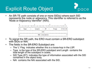
Downloaded 50 times

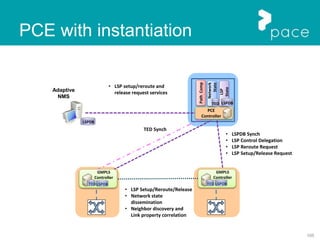
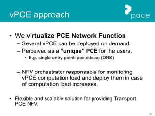
![58
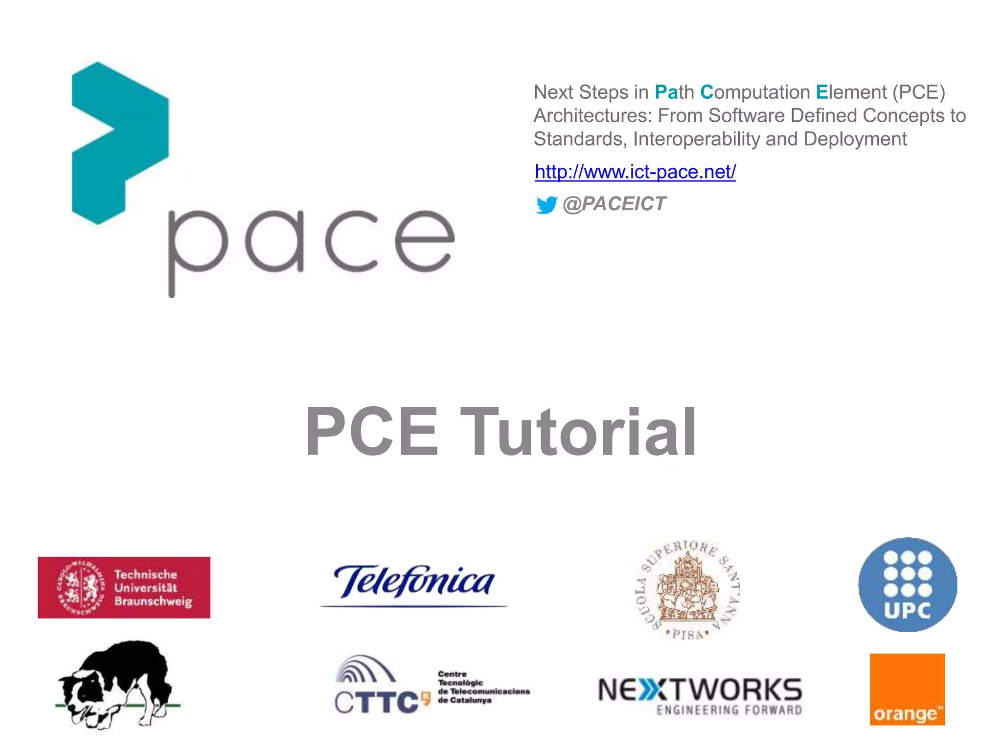
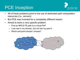
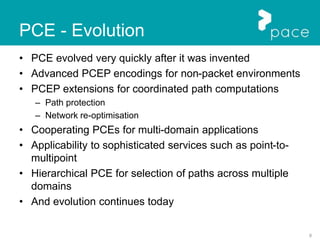
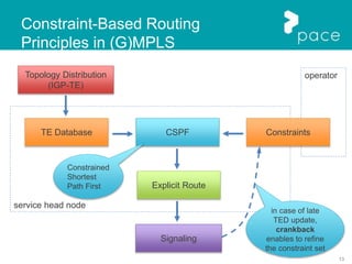
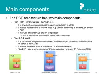
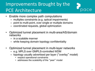
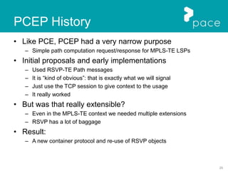
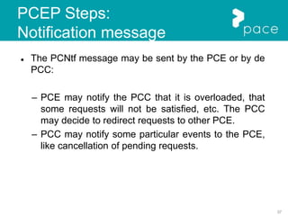
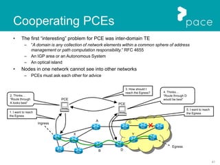
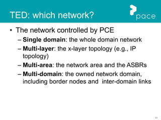
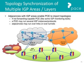
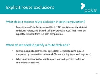
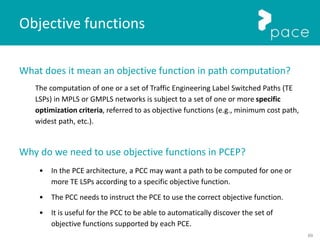
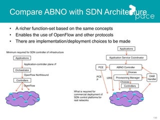
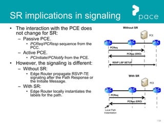
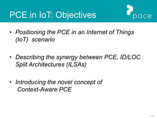
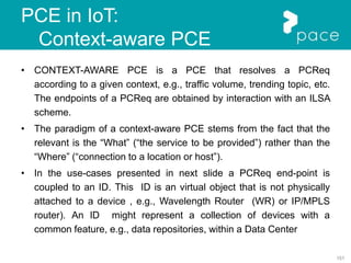
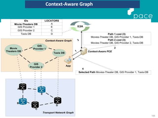
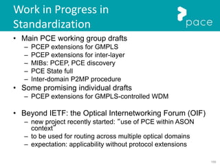
There are two types of route exclusion described in [RFC 4874]:
1. Exclusion of certain abstract nodes or resources from the whole path. This
set of abstract nodes is referred to as the Exclude Route List.
2. Exclusion of certain abstract nodes or resources between a specific pair of
abstract nodes present in an explicit path. Such specific exclusions are
referred to as an Explicit Route Exclusion.
New objects for route exclusions are defined in [RFC 5521]:
• New Exclude Route Object (XRO) is defined to convey the Exclude Route List
• Adding to the existing Include Route Object (IRO):
o The Explicit Exclusion Route subobject (EXRS) to convey Explicit Route
Exclusions.
Explicit route exclusions](https://image.slidesharecdn.com/pacepcetutorial-160314074637/85/FP7-PACE-PCE-Tutorial-58-320.jpg)
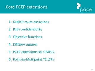
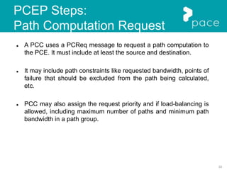
![64
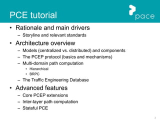
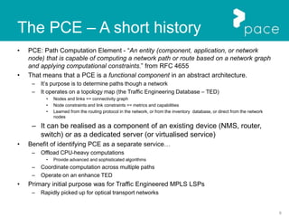
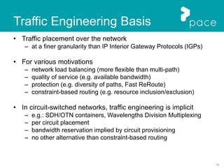
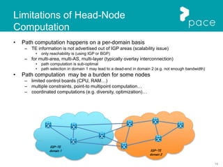
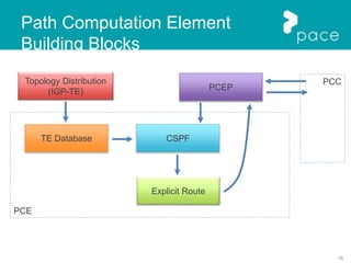
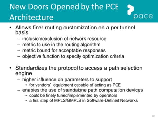
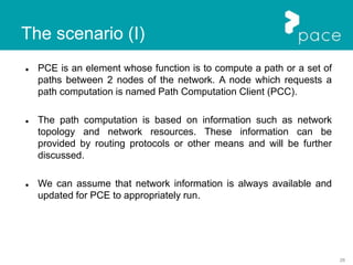
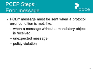
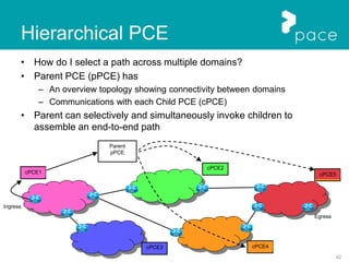
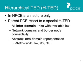
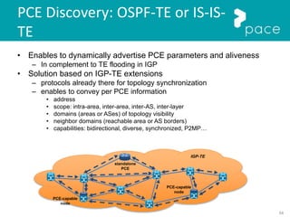
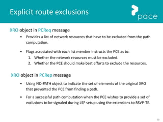
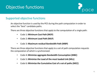
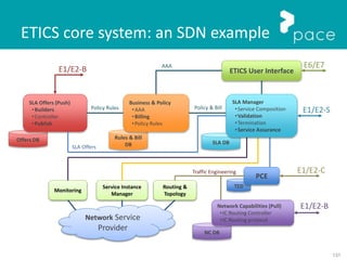
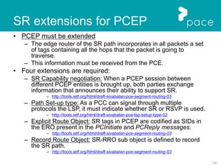
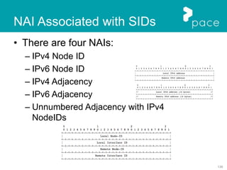
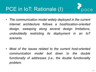
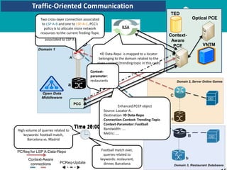
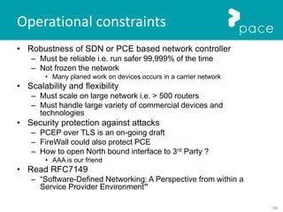
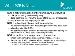
New object for path confidentiality is defined in [RFC 5520]:
• New Path-Key Subobject (PKS) is defined.
Path-Key
• Identifier used to represent the Confidential Path Segment (CPS) within the
context of the PCE identified by the PCE-ID.
PCE-ID
• Identifies the PCE that can decode the Path-Key using an identifier that is
unique within the domain that the PCE serves.
• Has to be mapped to a reachable IPv4 or IPv6 addr of the PCE by the first node
of the CPS and a PCE MAY use one of its reachable IP addresses as its PCE-ID.
Two subobjects are defined to allow IPv4 and IPv6 addresses to be carried:
• PKS with 32-Bit PCE ID and PKS with 128-Bit PCE ID
Path confidentiality
PKS = Path-Key + PCE-ID](https://image.slidesharecdn.com/pacepcetutorial-160314074637/85/FP7-PACE-PCE-Tutorial-64-320.jpg)


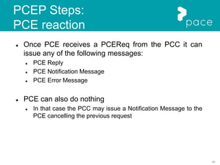
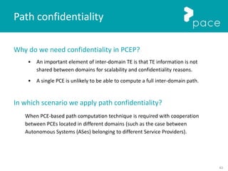
![71
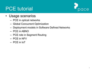
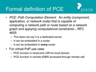
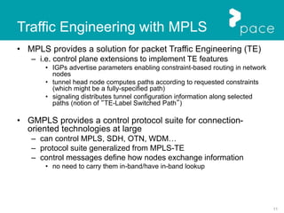
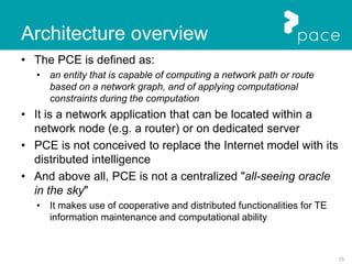
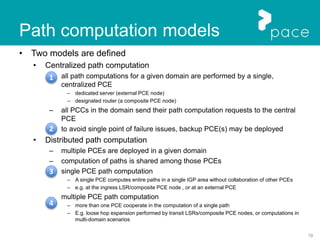
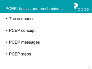
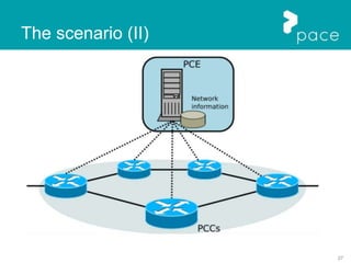
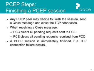
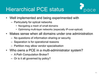
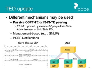
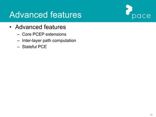
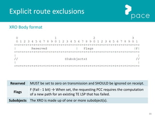
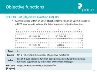
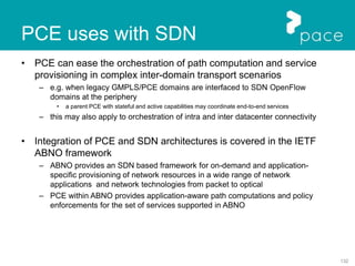
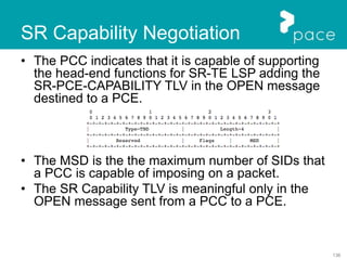
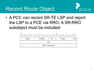
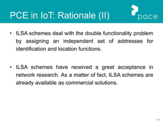
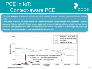
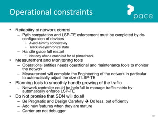
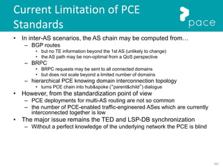
New Metric Types
Three metric types are specified in [RFC5440] for the METRIC object:
• Type 1: IGP metric
• Type 2: TE metric
• Type 3: hop count
Four new metrics for objective functions extension are defined in [RFC5541]:
• Type 4: Aggregate bandwidth consumption.
• Type 5: Load of the most loaded link.
• Type 6: Cumulative IGP cost.
• Type 7: Cumulative TE cost.
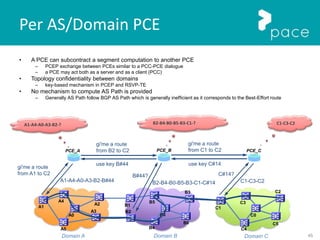
These metrics may be used in a:
• PCReq: to indicate a bound or to request the computation of a metric.
• PCRep: to indicate a computed metric.
Objective functions](https://image.slidesharecdn.com/pacepcetutorial-160314074637/85/FP7-PACE-PCE-Tutorial-71-320.jpg)

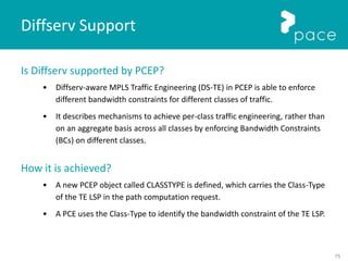
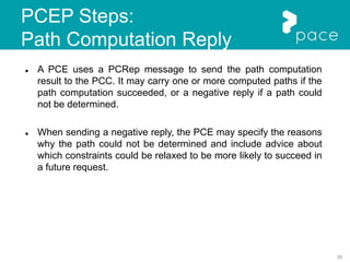
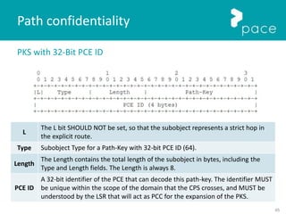
![76
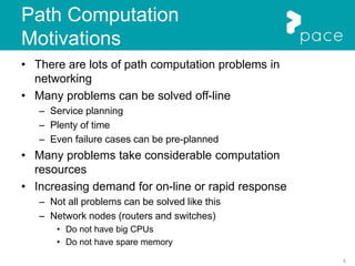
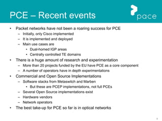
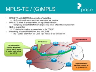
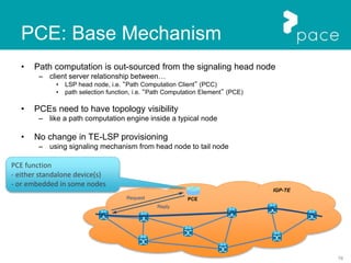
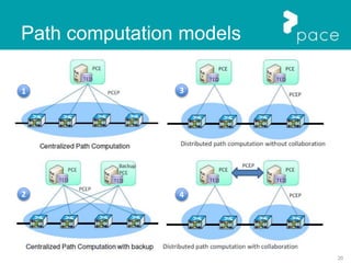
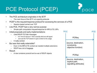
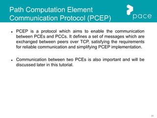
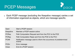
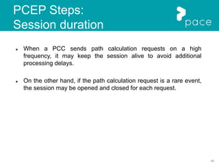
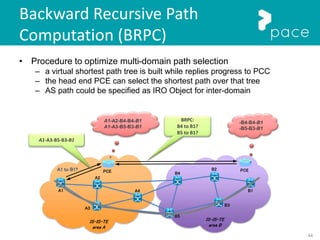
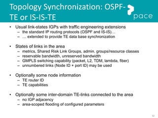
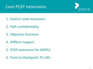
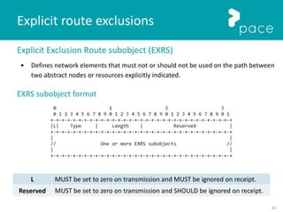
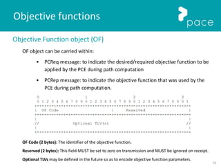
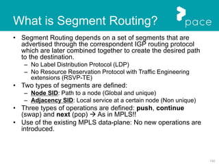
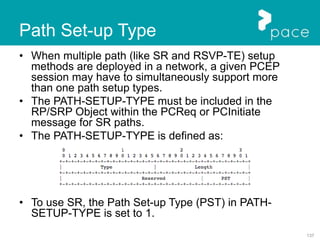
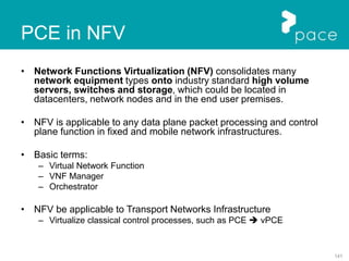
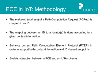
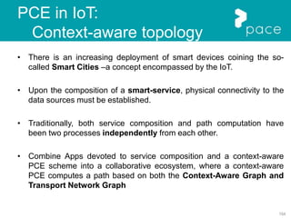
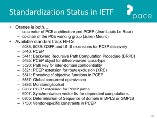
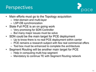
CLASSTYPE Object
• Used to specify the Class-Type of a Traffic Engineering Label Switched Path (TE LSP).
• If the TE LSP for which the path is to be computed belongs to Class 0, the PCReq
MUST NOT contain the CLASSTYPE object (backward compatibility).
The CLASSTYPE object contains a 32-bit word PCEP common object header defined in
[RFC5440].
CT: 3-bit field that indicates the Class-Type. Values allowed are 1,2, ... , 7. The value of 0 is Reserved.
Reserved: 29-bit reserved field. It MUST be set to zero on transmission and MUST be ignored on receipt.
Diffserv Support](https://image.slidesharecdn.com/pacepcetutorial-160314074637/85/FP7-PACE-PCE-Tutorial-76-320.jpg)
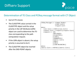
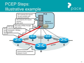
![78
Error codes for CLASSTYPE Object
Error types for Diffserv (defined in [RFC 5440])
● Error-Type = "Unknown Object": when the PCE does not recognize the
CLASSTYPE object .
● Error-Type = "Diffserv-aware TE error".
○ Error values (defined in [RFC 5455])
■ Error-value=1: Unsupported Class-Type ⇒ when a PCE does not
support the particular Class-Type.
■ Error-value=2: Invalid Class-Type ⇒ when a PCE determines that
the Class-Type value is not valid.
■ Error-value=3: Class-Type and setup priority do not form a
configured TE-class
Diffserv Support](https://image.slidesharecdn.com/pacepcetutorial-160314074637/85/FP7-PACE-PCE-Tutorial-78-320.jpg)
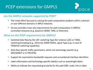
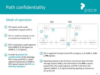
![84
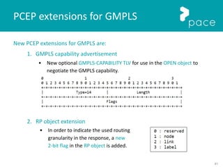
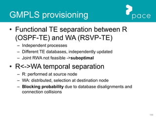
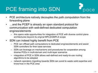
New PCEP extensions for GMPLS are:
5. END-POINTS Object extensions
• A new object type is introduced for the END-POINTS object
(GENERALIZED-ENDPOINT).
6. IRO and XRO extensions
• A new TLV type for label is allowed in IRO and XRO objects.
X: the X-bit indicates whether the exclusion is mandatory or desired.
Type: the Type of the XRO Label subobject is 3.
Length: the total length of the subobject in bytes (including the Type and Length fields).
U: See [RFC3471]
C-Type: The C-Type of the included Label Object as defined in [RFC3471].
Label: See [RFC3471].
PCEP extensions for GMPLS](https://image.slidesharecdn.com/pacepcetutorial-160314074637/85/FP7-PACE-PCE-Tutorial-84-320.jpg)
![85
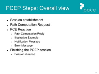
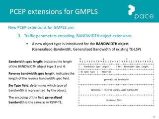
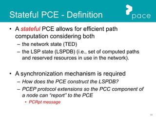
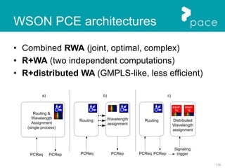
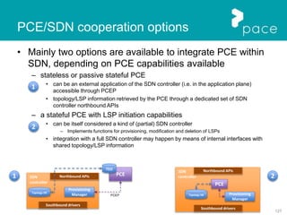
New PCEP extensions for GMPLS are:
8. LSPA extensions
• A new PROTECTION-ATTRIBUTE TLV is added to the LSPA object.
The content is as defined in [RFC4872], [RFC4873].
LSP Flags or Link flags field can be used by implementation for routing policy input.
9. NO-PATH Object Extension
• A new NO-PATH-VECTOR TLV added to the NO-PATH object
PCEP extensions for GMPLS](https://image.slidesharecdn.com/pacepcetutorial-160314074637/85/FP7-PACE-PCE-Tutorial-85-320.jpg)

![88
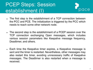
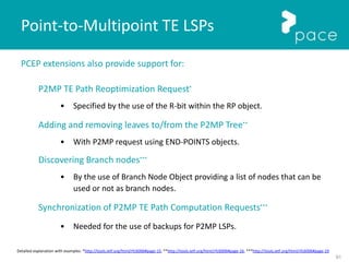
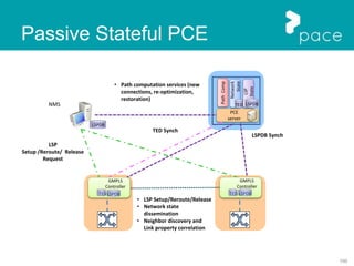
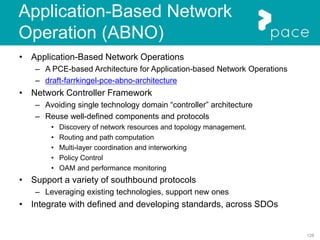
New PCEP extensions for P2MP TE LSPs:
Open Message Extension
• New optional TLV for PCEP OPEN object to indicate the PCE's capability
to perform P2MP path computations [RFC6006].
• IANA has allocated value 6 from the "PCEP TLV Type Indicators" sub-
registry. The description is "P2MP capable", and the length value is 2
bytes.
Efficient passing of P2MP LSPs between the PCE and PCC
• A new PCEP object class and type are requested for Secondary Explicit
Route Object (SERO) and the Secondary Record Route Object (SRRO).
• SERO and SRRO are used to report the route of an existing TE LSP for
which a reoptimization is desired. The format and content of the SERO
and SRRO are defined in [RFC4875].
Point-to-Multipoint TE LSPs](https://image.slidesharecdn.com/pacepcetutorial-160314074637/85/FP7-PACE-PCE-Tutorial-88-320.jpg)
![89
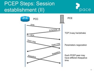
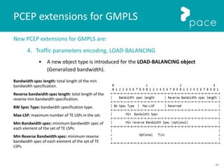
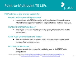
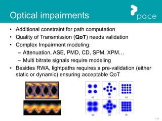
New PCEP extensions for P2MP TE LSPs:
Request and Reply Messages
• Modification of the PCReq and PCRep message to support P2MP, preserving
compatibility with the [RFC 5440], adding the following flags to the RP Object:
• The F-bit is added to the flag bits to indicate to the receiver that the request is part
of a fragmented request, or is not a fragmented request
• The N-bit is added in the flag bits field to signal the receiver of the message that the
request/reply is for P2MP or is not for P2MP.
• The E-bit is added in the flag bits field to signal the receiver of the message that the
route is in the compressed format or is not in the compressed format.
RP and END-POINTS objects extension
• RP extension in order to a PCC can signal a P2MP path computation
request to the PCE, receiving the PCEP request.
• END-points extension to improve the efficiency of the message exchange
between PCC and PCE in the case of P2MP path computation.
Point-to-Multipoint TE LSPs](https://image.slidesharecdn.com/pacepcetutorial-160314074637/85/FP7-PACE-PCE-Tutorial-89-320.jpg)
![90
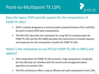
New PCEP extensions for P2MP TE LSPs:
P2MP Objective Functions
• Six objective functions have been defined in [RFC5541] for P2P path computation.
• The [RFC6006] adds two additional objective functions namely:
○ SPT (Shortest Path Tree) with code 7:
■ Minimize the maximum source-to-leaf cost with respect to a specific metric.
○ MCT (Minimum Cost Tree) that apply to P2MP path computation with code 8:
■ Minimize the total cost of the tree, that is the sum of the costs of tree links, with
respect to a specific metric.
New Metric Object Types
• There are three types defined for the <METRIC> object in [RFC5440]
• The [RFC6006] adds three additional types for the METRIC object:
– P2MP IGP metric: T=8
– P2MP TE metric: T=9
– P2MP hop count metric: T=10
Point-to-Multipoint TE LSPs](https://image.slidesharecdn.com/pacepcetutorial-160314074637/85/FP7-PACE-PCE-Tutorial-90-320.jpg)

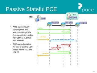
![98
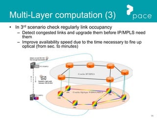
Stateful PCE - Motivation
• The lack of global LSP state information may result in sub-optimal
PCE algorithms. For example:
– Non-linear effects of optical fibers may cause the provisioning of a new optical
connection to degrade (QoS) of in-service connections.
• Impairment-aware RMSA algorithms should compute new paths that ensure an acceptable QoS of the
existing ones. To this end, impairment-aware RWA or RSA algorithms must also know the existing
LSPs in order to re-compute the considered QoS parameters (e.g., Q factor).
– Minimal perturbation problem route a demand along the path that requires the
lowest number of preemptions
• Without knowledge of LSPs, preempting low-priority LSPs based on the minimum number of links may
not result in the smallest number of LSPs being disrupted
• Information on the active LSP resource usage
– Conveyed in the request (e.g. GCO [5557])
• Not practical for a large number of connections, overhead, latency
– Available “somewhere else” or
– Managed in a Database (LSPDB), local to the PCE](https://image.slidesharecdn.com/pacepcetutorial-160314074637/85/FP7-PACE-PCE-Tutorial-98-320.jpg)
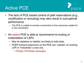
![120
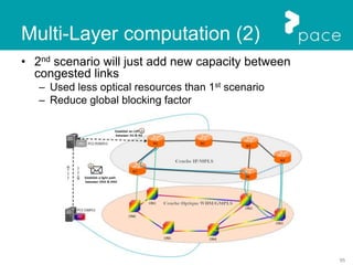
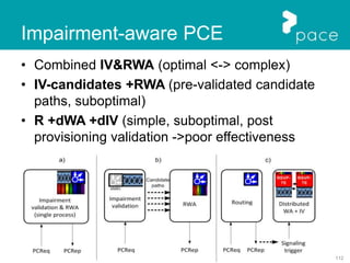
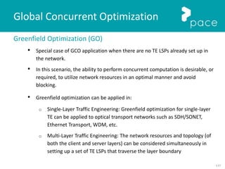
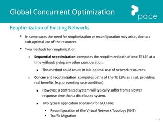
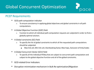
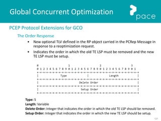
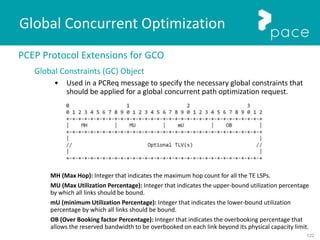
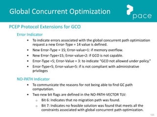
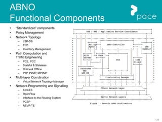
Global Concurrent Optimization
PCEP Protocol Extensions for GCO
Global Objective Function (GOF) Specification
• Three global objective functions defined in [RFC5541] are used in the
context of GCO:
o Minimize aggregated Bandwidth Consumption (MBC)
o Minimize the load of the Most Loaded Link (MLL)
o Minimize the Cumulative Cost of a set of paths
GCO Indicator
• A new flag in the SVEC object
Request for the order of the TE LSP
• To minimize disruption in case of bulk provisioning:
○ A new flag (D flag) in the RP object
• To support the determination of whether make-before-break optimization is
required:
○ A new flag (M flag) is defined in the RP object.](https://image.slidesharecdn.com/pacepcetutorial-160314074637/85/FP7-PACE-PCE-Tutorial-120-320.jpg)


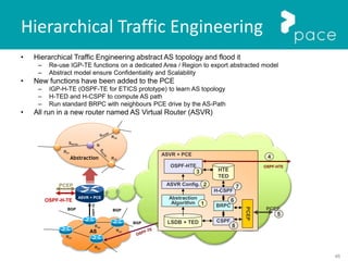
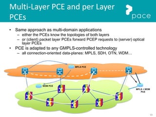
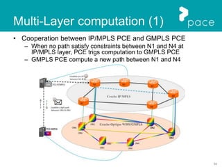
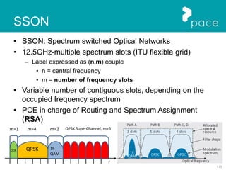
The document provides a comprehensive overview of Path Computation Element (PCE) architectures, discussing its definitions, historical context, and evolution. It outlines the roles of PCE in optimizing path computations for various networking scenarios, including MPLS and optical networks, while emphasizing the need for dedicated computation resources due to increased demand for efficient path routing. The document details the PCEP protocol, which facilitates communication between Path Computation Clients (PCCs) and PCEs, including its structure, message types, and operational steps.