More Related Content

PPTX

PPT
UNIT-3 network security layers andits types 
PPT
computer networks fundamentals in signal processing 
PPT
Network Layer packetizing and addressing.ppt 
PDF
Chapter_18 Introduction to Network Layer 
PDF

PPT

PDF
Computer Communication Networks-Network Layer Similar to Forouzan6e_ch07_PPTs_Network.pptxmcgrawhill

PPT

PPT

PPTX
Computer Communication Networks, network layer performance.pptx 
PPT
unit3- ppt computer networks - network layer 
PPTX
engineering cryptography 21ECE73 Module-3 (2).pptx 
PPT
Intro-network layer-chapter-18_forouzan.ppt 
PDF
packet switching network performance.pdf 
PPTX
Module 2.pptx.............sdvsdcdssdfsdf 
PPTX

PPTX
Forouzan6e_ch09_PPTs_Transport.pptxmcgrawhill 
PPTX
PDF
Network layer (Unit 3) part1.pdf 
PPTX
eeeeeeeeeeeeeeeeeeeeeeeeeeeeeeeeeeeeeeeeeeeeeeeeeeeee 
PPTX
unit 3 computer networks-switching,packet switching,internet protocol. 
PPTX

DOCX

PDF
Unit4DC_TransportLayer &NetworkLayer.pdf 
PPT
QSpiders - Good to Know Network Concepts 
PDF
Chapter_3 Transport Layer readfaecve.pdf 
PPTX
Recently uploaded

PPTX
Operational Amplifier (op - amp), types of op amp 
PPTX
analog communication part two lecture note 
PDF
Stiffness Matrix Method of Analysis for beams and frames 
PDF
Branches of AI – perception, reasoning, learning, and action.pdf 
PPTX
Biological Oxygen Demand (BOD) Numericals-2026.pptx 
PDF
graph graph graph theory Graph presentation .pdf 
PDF
UNIT02_TRE_GEOMETRIC DESIGN.pdf_________ 
PPTX
Design and Development of Friction Stir Welding joints of Aluminium and Coppe... 
PPTX
70,000 RPM Aerospace Bearing Testing – Why High-Speed Validation Is Critical 
PDF
The Eternal Citadel Architecture, Sacred Geography, and the Resilience of Som... 
PPTX
Web Technology Overview with list of assignments along with the technology 
PDF
Foundations and evolution of Artificial Intelligence - Mechanical Engineering... 
PDF
Flexibility Matrix Method of Analysis- Part B 
PPTX
Why Hydraulic Flushing Should Never Be Skipped Before Commissioning 
PDF
EPC vs Reality: The Schedule That Was Never Possible 
PDF
Yes, we put AI agents in production. No, don't try this at home 
PPTX
analog communication part one lecture note 
PDF
SURAJIT PARAMANIK_ME_3RD_THERMODYNAMICS.pdf 
PDF
Foundations of AI and ML - Mechanical Engineering Perspectives.pdf 
PDF
Performance_Metrics_Evolution_DannyJiang Forouzan6e_ch07_PPTs_Network.pptxmcgrawhill
- 1.
Because learning changeseverything.®
Chapter 07
Network Layer: Data
Transfer
Data Communications and
Networking, With TCP/IP
protocol suite
Sixth Edition
Behrouz A. Forouzan
© 2022 McGraw Hill, LLC. All rights reserved. Authorized only for instructor use in the classroom.
No reproduction or further distribution permitted without the prior written consent of McGraw Hill, LLC.
- 2.
© McGraw Hill,LLC 2
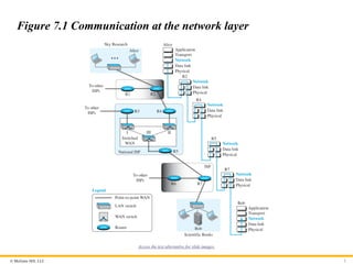
Figure 7.1 Communication at the network layer
Access the text alternative for slide images.
- 3.
© McGraw Hill,LLC 3
7-1 SERVICES
We briefly discuss the services provided at the network layer.
- 4.
© McGraw Hill,LLC 4
7.1.1 Packetizing
The first duty of the network layer is definitely packetizing:
encapsulating the payload in a network-layer packet at the source
and decapsulating the payload from the network-layer packet at the
destination. In other words, one duty of the network layer is to
carry a payload from the source to the destination without
changing it or using it. The network layer is doing the service of a
carrier such as the postal office, which is responsible for delivery
of packages from a sender to a receiver without changing or using
the contents.
- 5.
© McGraw Hill,LLC 5
7.1.2 Routing
Other duties of the network layer, which are as important as the
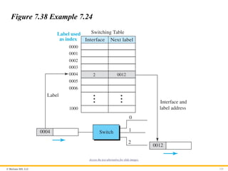
first, are routing and forwarding, which are directly related to each
other.
- 6.
© McGraw Hill,LLC 6
7.1.3 Error Control
Although error control can be implemented in the network layer,
the designers of the network layer in the Internet ignored this issue
for the data being carried by the network layer. One reason for this
decision is the fact that the packet in the network layer may be
fragmented at each router, which makes error checking at this
layer inefficient.
- 7.
© McGraw Hill,LLC 7
Chapter 7: Outline
7.1 Services
7.2 Packet Switching
7.3 Performance
7.4 Internet Protocol V4
7.5 Internet Protocol V6
7.6 Transition from V4 To V6
- 8.
© McGraw Hill,LLC 8
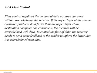
7.1.4 Flow Control
Flow control regulates the amount of data a source can send
without overwhelming the receiver. If the upper layer at the source
computer produces data faster than the upper layer at the
destination computer can consume it, the receiver will be
overwhelmed with data. To control the flow of data, the receiver
needs to send some feedback to the sender to inform the latter that
it is overwhelmed with data.
- 9.
© McGraw Hill,LLC 9
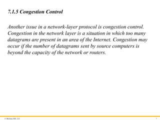
7.1.5 Congestion Control
Another issue in a network-layer protocol is congestion control.
Congestion in the network layer is a situation in which too many
datagrams are present in an area of the Internet. Congestion may
occur if the number of datagrams sent by source computers is
beyond the capacity of the network or routers.
- 10.
© McGraw Hill,LLC 10
7.1.6 Quality of Service
As the Internet has allowed new applications such as multimedia
communication (in particular real-time communication of audio
and video), the quality of service (QoS) of the communication has
become more and more important. The Internet has thrived by
providing better quality of service to support these applications.
However, to keep the network layer untouched, these provisions are
mostly implemented in the upper layer.
- 11.
© McGraw Hill,LLC 11
7.1.7 Security
Another issue related to communication at the network layer is
security. Security was not a concern when the Internet was
originally designed because it was used by a small number of users
at universities for research activities; other people had no access to
the Internet. The network layer was designed with no security
provision. Today, however, security is a big concern. To provide
security for a connectionless network layer, we need to have
another virtual level that changes the connectionless service to a
connection-oriented service.
- 12.
© McGraw Hill,LLC 12
7-2 PACKET SWITCHING
From the discussion of routing and forwarding in the
previous section, we infer that a kind of switching occurs at
the network layer. A router, in fact, is a switch that creates a
connection between an input port and an output port (or a
set of output ports), just as an electrical switch connects the
input to the output to let electricity flow.
- 13.
© McGraw Hill,LLC 13
7.2.1 Datagram Approach
When the Internet started, to make it simple, the network layer was
designed to provide a connectionless service in which the network-
layer protocol treats each packet independently, with each packet
having no relationship to any other packet. The idea was that the
network layer is only responsible for delivery of packets from the
source to the destination. In this approach, the packets in a
message may or may not travel the same path to their destination.
- 14.
© McGraw Hill,LLC 14
7.2.2 Virtual-Circuit Approach
In a connection-oriented service (also called virtual-circuit
approach), there is a relationship between all packets belonging to
a message. Before all datagrams in a message can be sent, a
virtual connection should be set up to define the path for the
datagrams. After connection setup, the datagrams can all follow
the same path. In this type of service, not only must the packet
contain the source and destination addresses, it must also contain a
flow label, a virtual circuit identifier that defines the virtual path
the packet should follow.
- 15.
© McGraw Hill,LLC 15
7-3 PERFORMANCE
The upper-layer protocols that use the service of the network
layer expect to receive an ideal service, but the network layer
is not perfect. The performance of a network can be
measured in terms of delay, throughput, and packet loss.
Congestion control is an issue that can improve the
performance.
- 16.
© McGraw Hill,LLC 16
7.3.1 Delay
All of us expect instantaneous response from a network, but a
packet, from its source to its destination, encounters delays. The
delays in a network can be divided into four types: transmission
delay, propagation delay, processing delay, and queuing delay. Let
us first discuss each of these delay types and then show how to
calculate a packet delay from the source to the destination.
- 17.
© McGraw Hill,LLC 17
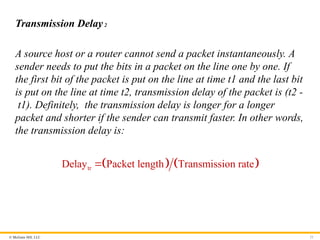
Transmission Delay1
A source host or a router cannot send a packet instantaneously. A
sender needs to put the bits in a packet on the line one by one. If
the first bit of the packet is put on the line at time t1 and the last bit
is put on the line at time t2, transmission delay of the packet is (t2 -
t1). Definitely, the transmission delay is longer for a longer
packet and shorter if the sender can transmit faster. In other words,
the transmission delay is .
tr
Delay Packet length Transmission rate
- 18.
© McGraw Hill,LLC 18
Propagation Delay
Propagation delay is the time it takes for a bit to travel from point
A to point B in the transmission media. The propagation delay for a
packet-switched network depends on the propagation delay of each
network (LAN or WAN). The propagation delay depends on the
propagation speed of the media, which is 3 ´ 108 meters/second in
a vacuum and normally much less in a wired medium; it also
depends on the distance of the link. In other words, propagation
delay is .
pg
Delay Distance Propagation speed
- 19.
© McGraw Hill,LLC 19
Processing Delay
The processing delay is the time required for a router or a
destination host to receive a packet from its input port, remove the
header, perform an error detection procedure, and deliver the
packet to the output port (in the case of a router) or deliver the
packet to the upper-layer protocol (in the case of the destination
host). The processing delay may be different for each packet, but
normally is calculated as an average.
pr
Delay Time required to process a packet
- 20.
© McGraw Hill,LLC 20
Total Delay
Assuming equal delays for the sender, routers, and receiver, the
total delay (source-to-destination delay) a packet encounters can
be calculated if we know the number of routers, n, in the whole
path.
qu
Delay The time a packet waits in queues
- 21.
© McGraw Hill,LLC 21
Transmission Delay2
A source host or a router cannot send a packet instantaneously. A
sender needs to put the bits in a packet on the line one by one. If
the first bit of the packet is put on the line at time t1 and the last bit
is put on the line at time t2, transmission delay of the packet is (t2 -
t1). Definitely, the transmission delay is longer for a longer
packet and shorter if the sender can transmit faster. In other words,
the transmission delay is:
tr
Delay Packet length Transmission rate
- 22.
© McGraw Hill,LLC 22
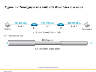
7.3.2 Throughput
Throughput at any point in a network is defined as the number of
bits passing through the point in a second, which is actually the
transmission rate of data at that point. In a path from source to
destination, a packet may pass through several links (networks),
each with a different transmission rate. How, then, can we
determine the throughput of the whole path? To see the situation,
assume that we have three links, each with a different transmission
rate, as shown in Figure 7.2.
- 23.
© McGraw Hill,LLC 23
Figure 7.2 Throughput in a path with three links in a series
Access the text alternative for slide images.
- 24.
© McGraw Hill,LLC 24
Figure 7.3 A path through the Internet backbone
Access the text alternative for slide images.
- 25.
© McGraw Hill,LLC 25
7.3.3 Packet Loss
Another issue that severely affects the performance of
communication is the number of packets lost during transmission.
When a router receives a packet while processing another packet,
the received packet needs to be stored in the input buffer waiting
for its turn. A router, however, has an input buffer with a limited
size. A time may come when the buffer is full and the next packet
needs to be dropped. The effect of packet loss on the Internet
network layer is that the packet needs to be resent, which in turn
may create overflow and cause more packet loss.
- 26.
© McGraw Hill,LLC 26
7.3.4 Congestion Control
Congestion control is a mechanism for improving performance.
Although congestion at the network layer is not explicitly
addressed in the Internet model, the study of congestion at this
layer may help us to better understand the cause of congestion at
the transport layer and find possible remedies to be used at the
network layer. Congestion at the network layer is related to two
issues, throughput and delay, which we discussed in the previous
section.
- 27.
© McGraw Hill,LLC 27
7-4 INTERNET PROTOCOL VERSION 4
The network layer in the Internet has gone through several
versions, but only two versions have survived: IP Version 4
(IPv4) and IP Version 6 (IPv6). Although IPv4 is almost
depleted, we discuss it because there are still some areas
that use this version and also because it is the foundation for
IPv6.
- 28.
© McGraw Hill,LLC 28
7.4.1 IPv4 Addressing
The identifier used in the IP layer of the TCP/IP protocol suite to
identify the connection of each device to the Internet is called the
Internet address or IP address. An IPv4 address is a 32-bit address
that uniquely and universally defines the connection of a host or a
router to the Internet. The IP address is the address of the
connection, not the host or the router, because if the device is
moved to another network, the IP address may be changed.
- 29.
© McGraw Hill,LLC 29
Address Space1
A protocol like IPv4 that defines addresses has an address space.
An address space is the total number of addresses used by the
protocol. If a protocol uses b bits to define an address, the address
space is 2b because each bit can have two different values (0 or 1).
IPv4 uses 32-bit addresses, which means that the address space is
232 or 4,294,967,296 (more than four billion). If there were no
restrictions, more than 4 billion devices could be connected to the
Internet.
- 30.
© McGraw Hill,LLC 30
Notation
There are three common notations to show an IPv4 address: binary
notation (base 2), dotted-decimal notation (base 256), and
hexadecimal notation (base 16).
- 31.
© McGraw Hill,LLC 31
Figure 7.4 Three different notations in IPv4 addressing
Access the text alternative for slide images.
- 32.
© McGraw Hill,LLC 32
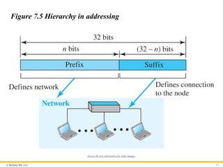
Hierarchy in Addressing
In any communication network that involves delivery, such as a
telephone network or a postal network, the addressing system is
hierarchical. A 32-bit IPv4 address is also hierarchical but divided
only into two parts. The first part of the address, called the prefix,
defines the network; the second part of the address, called the
suffix, defines the node.
- 33.
© McGraw Hill,LLC 33
Figure 7.5 Hierarchy in addressing
Access the text alternative for slide images.
- 34.
© McGraw Hill,LLC 34
Classful Addressing
When the Internet started, an IPv4 address was designed with a
fixed-length prefix, but to accommodate both small and large
networks, three fixed-length prefixes were designed instead of one
(n = 8, n = 16, and n = 24). The whole address space was divided
into five classes (class A, B, C, D, and E), as shown in Figure 7.6.
This scheme is referred to as classful addressing. Although classful
addressing belongs to the past, it helps us to understand classless
addressing, discussed later.
- 35.
© McGraw Hill,LLC 35
Figure 7.6 Occupation of the address space in classful addressing
Access the text alternative for slide images.
- 36.
© McGraw Hill,LLC 36
Classless Addressing
With the growth of the Internet, it was clear that a larger address
space was needed as a long-term solution. The larger address
space, however, requires that the length of IP addresses also be
increased, which means the format of the IP packets needs to be
changed. Although the long-range solution has already been
devised and is called IPv6, a short-term solution was also devised
to use the same address space but to change the distribution of
addresses to provide a fair share to each organization. The short-
term solution still uses IPv4 addresses, but it is called classless
addressing.
- 37.
© McGraw Hill,LLC 37
Figure 7.7 Variable-length blocks in classless addressing
Access the text alternative for slide images.
- 38.
© McGraw Hill,LLC 38
Figure 7.8 Slash notation (CIDR)
Access the text alternative for slide images.
- 39.
© McGraw Hill,LLC 39
Example 7.1
A classless address is given as 167.199.170.82/27. We can find the
above three pieces of information as follows. The number of
addresses in the network is 32
2 25 32
n
addresses. The first
address can be found by keeping the first 27 bits and changing the
rest of the bits to 0s.
Address: 167.199.170.82/27 10100111 11000111 10101010 01010010
First address: 167.199.170.64/27 10100111 11000111 10101010 01000000
The last address can be found by keeping the first 27 bits and
changing the rest of the bits to 1s.
Address: 167.199.170.82/27 10100111 11000111 10101010 01011111
Last address: 167.199.170.95/27 10100111 11000111 10101010 01011111
- 40.
© McGraw Hill,LLC 40
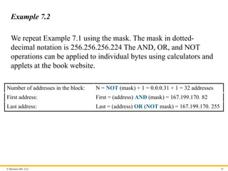
Example 7.2
We repeat Example 7.1 using the mask. The mask in dotted-
decimal notation is 256.256.256.224 The AND, OR, and NOT
operations can be applied to individual bytes using calculators and
applets at the book website.
Number of addresses in the block: N = NOT (mask) + 1 = 0.0.0.31 + 1 = 32 addresses
First address: First = (address) AND (mask) = 167.199.170. 82
Last address: Last = (address) OR (NOT mask) = 167.199.170. 255
- 41.
© McGraw Hill,LLC 41
Example 7.3
In classless addressing, an address cannot per se define the block
the address belongs to. For example, the address 230.8.24.56 can
belong to many blocks. Some of them are shown below with the
value of the prefix associated with that block.
Prefix length:16 → Block: 230.8.0.0 to 230.8.255.255
Prefix length:20 → Block: 230.8.16.0 to 230.8.31.255
Prefix length:26 → Block: 230.8.24.0 to 230.8.24.63
Prefix length:27 → Block: 230.8.24.32 to 230.8.24.63
Prefix length:29 → Block: 230.8.24.56 to 230.8.24.63
Prefix length:31 → Block: 230.8.24.56 to 230.8.24.57
- 42.
© McGraw Hill,LLC 42
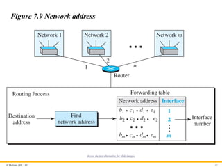
Figure 7.9 Network address
Access the text alternative for slide images.
- 43.
© McGraw Hill,LLC 43
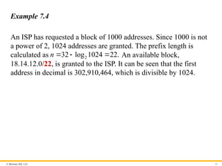
Example 7.4
An ISP has requested a block of 1000 addresses. Since 1000 is not
a power of 2, 1024 addresses are granted. The prefix length is
calculated as 2
32 log 1024 22.
n An available block,
18.14.12.0/22, is granted to the ISP. It can be seen that the first
address in decimal is 302,910,464, which is divisible by 1024.
- 44.
© McGraw Hill,LLC 44
Example 7.5(1)
An organization is granted a block of addresses with the beginning
address 14.24.74.0/24. The organization needs to have 3 subblocks
of addresses to use in its three subnets: one subblock of 10
addresses, one subblock of 60 addresses, and one subblock of 120
addresses. Design the subblocks.
Solution
There are 32–24
2 256
addresses in this block. The first address is
14.24.74.0/24; the last address is 14.24.74.255/24. To satisfy the
third requirement, we assign addresses to subblocks, starting with
the largest and ending with the smallest one.
- 45.
© McGraw Hill,LLC 45
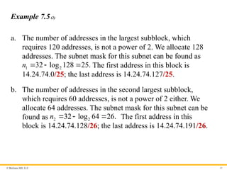
Example 7.5(2)
a. The number of addresses in the largest subblock, which
requires 120 addresses, is not a power of 2. We allocate 128
addresses. The subnet mask for this subnet can be found as
1 2
32 log 128 25.
n The first address in this block is
14.24.74.0/25; the last address is 14.24.74.127/25.
b. The number of addresses in the second largest subblock,
which requires 60 addresses, is not a power of 2 either. We
allocate 64 addresses. The subnet mask for this subnet can be
found as 2 2
32 log 64 26.
n The first address in this
block is 14.24.74.128/26; the last address is 14.24.74.191/26.
- 46.
© McGraw Hill,LLC 46
Example 7.5(3)
c. The number of addresses in the largest subblock, which
requires 120 addresses, is not a power of 2. We allocate 128
addresses. The subnet mask for this subnet can be found as
1 2
32 log 128 25.
n The first address in this block is
14.24.74.0/25; the last address is 14.24.74.127/25.
If we add all addresses in the previous subblocks, the result is
208 addresses, which means 48 addresses are left in reserve. The
first address in this range is 14.24.74.208. The last address is
14.24.74.255. We don’t know about the prefix length yet. Figure
4.36 shows the configuration of blocks. We have shown the first
address in each block.
- 47.
© McGraw Hill,LLC 47
Figure 7.10 Solution to Example 4.5
Access the text alternative for slide images.
- 48.
© McGraw Hill,LLC 48
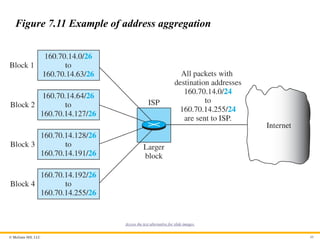
Example 7.6
Figure 7.11 shows how four small blocks of addresses are assigned
to four organizations by an ISP. The ISP combines these four
blocks into one single block and advertises the larger block to the
rest of the world. Any packet destined for this larger block should
be sent to this ISP. It is the responsibility of the ISP to forward the
packet to the appropriate organization. This is similar to routing we
can find in a postal network. All packages coming from outside a
country are sent first to the capital and then distributed to the
corresponding destination.
- 49.
© McGraw Hill,LLC 49
Figure 7.11 Example of address aggregation
Access the text alternative for slide images.
- 50.
© McGraw Hill,LLC 50
7.4.2 Four Related Protocols
The network layer in version 4 can be thought of as one main
protocol and three auxiliary ones. The main protocol, IPv4, is
responsible for packetizing, forwarding, and delivery of a
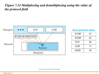
packet. The ICMPv4 helps IPv4 to handle some errors that
may occur in delivery. The IGMP is used to help IPv4 in
multicasting. ARP is used in address mapping.
- 51.
© McGraw Hill,LLC 51
Figure 7.12 Position of IP and other network-layer protocols in
TCP/IP protocol suite
Access the text alternative for slide images.
- 52.
© McGraw Hill,LLC 52
Datagram Format
Packets used by the IP are called datagrams. Figure 7.13 shows
the IPv4 datagram format. A datagram is a variable-length packet
consisting of two parts: header and payload (data). The header is
20 to 60 bytes in length and contains information essential to
routing and delivery. It is customary in TCP/IP to show the header
in 4-byte sections.
- 53.
© McGraw Hill,LLC 53
Figure 7.13 IP datagram
Access the text alternative for slide images.
- 54.
© McGraw Hill,LLC 54
Figure 7.14 Multiplexing and demultiplexing using the value of
the protocol field
Access the text alternative for slide images.
- 55.
© McGraw Hill,LLC 55
Example 7.7
An IPv4 packet has arrived with the first 8 bits as 2
01000010 .
The receiver discards the packet. Why?
Solution
There is an error in this packet. The 4 leftmost bits (0100)2 show
the version, which is correct. The next 4 bits (0010)2 show an
invalid header length (2 * 4 = 8). The minimum number of bytes in
the header must be 20. The packet has been corrupted in
transmission.
- 56.
© McGraw Hill,LLC 56
Example 7.8
In an IPv4 packet, the value of HLEN is 2
1000 . How many bytes
of options are being carried by this packet?
Solution
The HLEN value is 8, which means the total number of bytes in the
header is 8 * 4, or 32 bytes. The first 20 bytes are the base header,
the next 12 bytes are the options.
- 57.
© McGraw Hill,LLC 57
Example 7.9
In an IPv4 packet, the value of HLEN is 5, and the value of the
total length field is 16
0028 . How many bytes of data are being
carried by this packet?
Solution
The HLEN value is 5, which means the total number of bytes in the
header is 5 * 4, or 20 bytes (no options). The total length is 16
0028
or 40 bytes, which means the packet is carrying 20 bytes of data
(40 - 20).
- 58.
© McGraw Hill,LLC 58
Example 7.10
An IPv4 packet has arrived with the first few hexadecimal digits as
shown
16
45000028000100000102
How many hops can this packet travel before being dropped? The
data belong to what upper-layer protocol?
Solution
To find the time-to-live field, we skip 8 bytes (16 hexadecimal
digits). The time-to-live field is the ninth byte, which is 16
01 .This
means the packet can travel only one hop. The protocol field is the
next byte 16
02 , which means that the upper-layer protocol is
IGMP.
- 59.
© McGraw Hill,LLC 59
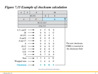
Example 7.11
Figure 7.15 shows an example of a checksum calculation for an
IPv4 header without options. The header is divided into 16-bit
sections. All the sections are added and the sum is complemented
after wrapping the leftmost digit. The result is inserted in the
checksum field.
- 60.
© McGraw Hill,LLC 60
Figure 7.15 Example of checksum calculation
Access the text alternative for slide images.
- 61.
© McGraw Hill,LLC 61
Fragmentation
A datagram can travel through different networks. Each router
decapsulates the IP datagram from the frame it receives, processes
it, and then encapsulates it in another frame. The format and size
of the received frame depend on the protocol used by the physical
network through which the frame has just traveled. The format and
size of the sent frame depend on the protocol used by the physical
network through which the frame is going to travel. For example, if
a router connects a LAN to a WAN, it receives a frame in the LAN
format and sends a frame in the WAN format.
- 62.
© McGraw Hill,LLC 62
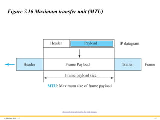
Maximum Transfer Unit
Each link-layer protocol has its own frame format. One of the
features of each format is the maximum size of the payload that can
be encapsulated in a frame, total size of the datagram must be less
than the maximum size (see Figure 7.16).
- 63.
© McGraw Hill,LLC 63
Figure 7.16 Maximum transfer unit (MTU)
Access the text alternative for slide images.
- 64.
© McGraw Hill,LLC 64
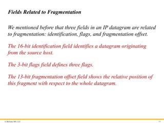
Fields Related to Fragmentation
We mentioned before that three fields in an IP datagram are related
to fragmentation: identification, flags, and fragmentation offset.
The 16-bit identification field identifies a datagram originating
from the source host.
The 3-bit flags field defines three flags.
The 13-bit fragmentation offset field shows the relative position of
this fragment with respect to the whole datagram.
- 65.
© McGraw Hill,LLC 65
Figure 7.18 Detailed fragmentation example
Access the text alternative for slide images.
- 66.
© McGraw Hill,LLC 66
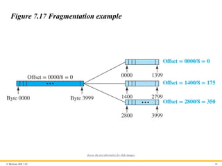
Figure 7.17 Fragmentation example
Access the text alternative for slide images.
- 67.
© McGraw Hill,LLC 67
Example 7.12
A packet has arrived with an M bit value of 0. Is this the first
fragment, the last fragment, or a middle fragment? Do we know if
the packet was fragmented?
Solution
If the M bit is 0, it means that there are no more fragments; the
fragment is the last one. However, we cannot say if the original
packet was fragmented or not. A non-fragmented packet is
considered the last fragment.
- 68.
© McGraw Hill,LLC 68
Example 7.13
A packet has arrived with an M bit value of 1. Is this the first
fragment, the last fragment, or a middle fragment? Do we know if
the packet was fragmented?
Solution
If the M bit is 1, it means that there is at least one more fragment.
This fragment can be the first one or a middle one, but not the last
one. We don’t know if it is the first one or a middle one; we need
more information (the value of the fragmentation offset).
- 69.
© McGraw Hill,LLC 69
Example 7.14
A packet has arrived with an M bit value of 1 and a fragmentation
offset value of 0. Is this the first fragment, the last fragment, or a
middle fragment?
Solution
Because the M bit is 1, it is either the first fragment or a middle
one. Because the offset value is 0, it is the first fragment.
- 70.
© McGraw Hill,LLC 70
Example 7.15
A packet has arrived in which the offset value is 100. What is the
number of the first byte? Do we know the number of the last byte?
Solution
To find the number of the first byte, we multiply the offset value by
8. This means that the first byte number is 800. We cannot
determine the number of the last byte unless we know the length of
the data.
- 71.
© McGraw Hill,LLC 71
Example 7.16
A packet has arrived in which the offset value is 100, the value of
HLEN is 5, and the value of the total length field is 100. What are
the numbers of the first byte and the last byte?
Solution
The first byte number is 100 * 8 = 800. The total length is 100
bytes, and the header length is 20 bytes (5 * 4), which means that
there are 80 bytes in this datagram. If the first byte number is 800,
the last byte number must be 879.
- 72.
© McGraw Hill,LLC 72
7.4.3 Options
The header of the IPv4 datagram is made of two parts: a fixed part
and a variable part. The fixed part is 20 bytes long and was
discussed in the previous section. The variable part comprises the
options that can be a maximum of 40 bytes (in multiples of 4 bytes)
to preserve the boundary of the header.
- 73.
© McGraw Hill,LLC 73
Single-Byte Options
There are two single-byte options.
No Operation
A no-operation option is a 1-byte option used as a filler between
options.
End of Option
An end-of-option option is a 1-byte option used for padding at the
end of the option field. It, however, can only be used as the last
option.
- 74.
© McGraw Hill,LLC 74
Security of IPv4 Datagrams
We give a brief idea about the security issues in IP protocol.
Packet Sniffing
An intruder may intercept an IP packet and make a copy of it.
Packet Modification
The attacker intercepts the packet, changes its contents, and sends
the new packet to the receiver..
IP Spoofing
An attacker can masquerade as somebody else and create an IP
packet that carries the source address of another computer.
- 75.
© McGraw Hill,LLC 75
IPSec
The IP packets today can be protected from the previously
mentioned attacks using a protocol called IPSec (IP Security). This
protocol, which is used in conjunction with the IP protocol, creates
a connection-oriented service between two entities in which they
can exchange IP packets without worrying about the three attacks
discussed above. We will discuss IPSec in detail in Chapter 13.
- 76.
© McGraw Hill,LLC 76
7.4.4 ICMPv4
The IPv4 has no error-reporting or error-correcting
mechanism. The IP protocol also lacks a mechanism for host
and management queries. The Internet Control Message
Protocol version 4 (ICMPv4) has been designed to
compensate for the above two deficiencies.
- 77.
© McGraw Hill,LLC 77
Messages
ICMP messages are divided into two broad categories: error-
reporting messages and query messages. The error-reporting
messages report problems that a router or a host (destination) may
encounter when it processes an IP packet. The query messages,
which occur in pairs, help a host or a network manager get specific
information from a router or another host. For example, nodes can
discover their neighbors. Also, hosts can discover and learn about
routers on their network and routers can help a node redirect its
messages.
- 78.
© McGraw Hill,LLC 78
Figure 7.19 General format of ICMP messages
Access the text alternative for slide images.
- 79.
© McGraw Hill,LLC 79
Figure 7.20 Contents of data field for error messages
Access the text alternative for slide images.
- 80.
© McGraw Hill,LLC 80
Deprecated Messages
Three pairs of messages are declared obsolete by IETF:
1. Information request and replay messages
2. Address mask request and reply messages
3. Router solicitation and advertisement messages
- 81.
© McGraw Hill,LLC 81
Debugging Tools
There are several tools that can be used in the Internet for
debugging. We can determine the viability of a host or router. We
can trace the route of a packet. We introduce two tools that use
ICMP for debugging: ping and traceroute.
- 82.
© McGraw Hill,LLC 82
Ping
We can use the ping program to find if a host is alive and is
responding.
- 83.
© McGraw Hill,LLC 83
Example 7.17
The following shows how we send a ping message to the
auniversity.edu site.
$ ping auniversity.edu
PING auniversity.edu (152.181.8.3) 56 (84) bytes of data. ttl=62 time=1.91 ms
64 bytes from auniversity.edu (152.181.8.3): icmp_seq=0 ttl=62 time=2.04 ms
64 bytes from auniversity.edu (152.181.8.3): icmp_seq=1 ttl=62 time=1.90 ms
64 bytes from auniversity.edu (152.181.8.3): icmp_seq=2 ttl=62 time=1.90 ms
64 bytes from auniversity.edu (152.181.8.3): icmp_seq=3 ttl=62 time=1.97 ms
64 bytes from auniversity.edu (152.181.8.3): icmp_seq=4 ttl=62 time=1.93 ms
64 bytes from auniversity.edu (152.181.8.3): icmp_seq=5 ttl=62 time=2.00 ms
--- auniversity.edu statistics ---
6 packets transmitted, 6 received, 0% packet loss
rtt min/avg/max = 1.90/1.95/2.04 ms
- 84.
© McGraw Hill,LLC 84
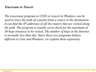
Traceroute or Tracert
The traceroute program in UNIX or tracert in Windows can be
used to trace the path of a packet from a source to the destination.
It can find the IP addresses of all the routers that are visited along
the path. The program is usually set to check for the maximum of
30 hops (routers) to be visited. The number of hops in the Internet
is normally less than this. Since these two programs behave
different in Unix and Windows, we explain them separately.
- 85.
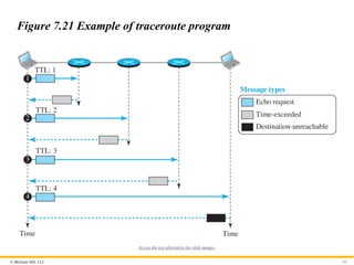
© McGraw Hill,LLC 85
Figure 7.21 Example of traceroute program
Access the text alternative for slide images.
- 86.
© McGraw Hill,LLC 86
ICMP Checksum
In ICMP, the checksum is calculated over the entire message
(header and data).
- 87.
© McGraw Hill,LLC 87
Example 7.18
Figure 7.22 shows an example of checksum calculation for a
simple echo-request message. We randomly chose the identifier to
be 1 and the sequence number to be 9. The message is divided into
16-bit (2-byte) words. The words are added and the sum is
complemented. Now the sender can put this value in the checksum
field.
- 88.
© McGraw Hill,LLC 88
Figure 7.22 Example of checksum calculation
Access the text alternative for slide images.
- 89.
© McGraw Hill,LLC 89
7.4.5 Mobile IP
In the last section of this chapter, we discuss mobile IP. As mobile
and personal computers such as notebooks become increasingly
popular, we need to think about mobile IP, the extension of IP
protocol that allows mobile computers to be connected to the
Internet at any location where the connection is possible. In this
section, we discuss this issue.
- 90.
© McGraw Hill,LLC 90
Addressing
The main problem that must be solved in providing mobile
communication using the IP protocol is addressing.
- 91.
© McGraw Hill,LLC 91
Figure 7.23 Home address and care-of address
Access the text alternative for slide images.
- 92.
© McGraw Hill,LLC 92
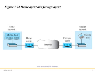
Agents
To make the change of address transparent to the rest of the
Internet requires a home agent and a foreign agent. Figure 7.24
shows the position of a home agent relative to the home network
and a foreign agent relative to the foreign network.
- 93.
© McGraw Hill,LLC 93
Figure 7.24 Home agent and foreign agent
Access the text alternative for slide images.
- 94.
© McGraw Hill,LLC 94
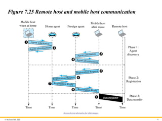
Three Phases
To communicate with a remote host, a mobile host goes through
three phases: agent discovery, registration, and data transfer, as
shown in Figure 7.25.
- 95.
© McGraw Hill,LLC 95
Figure 7.25 Remote host and mobile host communication
Access the text alternative for slide images.
- 96.
© McGraw Hill,LLC 96
Figure 7.26 Agent advertisement
Access the text alternative for slide images.
- 97.
© McGraw Hill,LLC 97
Table 7.1 Code Bits
Bit Meaning
0 Registration required. No collocated care-of address.
1 Agent is busy and does not accept registration at this moment.
2 Agent acts as a home agent.
3 Agent acts as a foreign agent.
4 Agent uses minimal encapsulation.
5 Agent uses generic routing encapsulation (GRE).
6 Agent uses generic routing encapsulation (GRE).
7 Unused (0).
- 98.
© McGraw Hill,LLC 98
Registration
The second phase in mobile communication is registration. After a
mobile host has moved to a foreign network and discovered the
foreign agent, it must register. There are four aspects of
registration:
1. The mobile host must register itself with the foreign agent.
2. The mobile host must register itself with its home agent.
3. The mobile host must renew registration if it has expired.
4. The mobile host must cancel its registration when it returns.
- 99.
© McGraw Hill,LLC 99
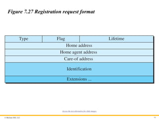
Figure 7.27 Registration request format
Access the text alternative for slide images.
- 100.
© McGraw Hill,LLC 100
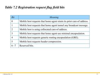
Table 7.2 Registration request flag field bits
Bit Meaning
0 Mobile host requests that home agent retain its prior care-of address.
1 Mobile host requests that home agent tunnel any broadcast message.
2 Mobile host is using collocated care-of address.
3 Mobile host requests that home agent use minimal encapsulation.
4 Mobile host requests generic routing encapsulation (GRE).
5 Mobile host requests header compression.
6 –7 Reserved bits.
- 101.
© McGraw Hill,LLC 101
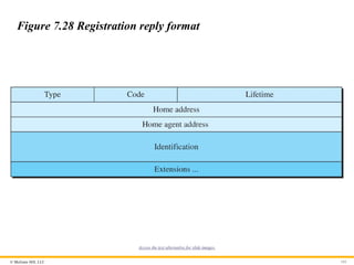
Figure 7.28 Registration reply format
Access the text alternative for slide images.
- 102.
© McGraw Hill,LLC 102
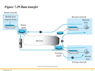
Data Transfer
After agent discovery and registration, a mobile host can
communicate with a remote host. Figure 7.29 shows the idea.
- 103.
© McGraw Hill,LLC 103
Figure 7.29 Data transfer
Access the text alternative for slide images.
- 104.
© McGraw Hill,LLC 104
Figure 7.30 Double crossing
Access the text alternative for slide images.
- 105.
© McGraw Hill,LLC 105
Figure 7.31 Triangle routing
Access the text alternative for slide images.
- 106.
© McGraw Hill,LLC 106
7.4.6 Forwarding of IP Packets
We discussed the concept of forwarding at the network layer earlier
in this chapter. In this section, we extend the concept to include the
role of IP addresses in forwarding. As we discussed before,
forwarding means to place the packet in its route to its destination.
Since the Internet today is made of a combination of links
(networks), forwarding means to deliver the packet to the next hop
(which can be the final destination or the intermediate connecting
device). Although the IP protocol was originally designed as a
connectionless protocol, today the tendency is to change it to
connection-oriented protocol. We discuss both cases.
- 107.
© McGraw Hill,LLC 107
Forwarding Based on Destination Address
We first discuss forwarding based on the destination address. This
is a traditional approach, which is prevalent today. In this case,
forwarding requires a host or a router to have a forwarding table.
When a host has a packet to send or when a router has received a
packet to be forwarded, it looks at this table to find the next hop to
deliver the packet to.
- 108.
© McGraw Hill,LLC 108
Figure 7.32 Simplified forwarding module in classless address
Access the text alternative for slide images.
- 109.
© McGraw Hill,LLC 109
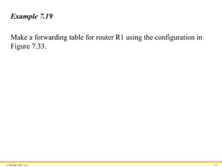
Example 7.19
Make a forwarding table for router R1 using the configuration in
Figure 7.33.
- 110.
© McGraw Hill,LLC 110
Figure 7.33 Configuration for Example 7.19
Access the text alternative for slide images.
- 111.
© McGraw Hill,LLC 111
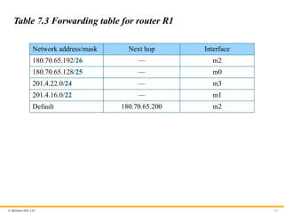
Table 7.3 Forwarding table for router R1
Network address/mask Next hop Interface
180.70.65.192/26 — m2
180.70.65.128/25 — m0
201.4.22.0/24 — m3
201.4.16.0/22 — m1
Default 180.70.65.200 m2
- 112.
© McGraw Hill,LLC 112
Example 7.20
Instead of Table 7.3, we can use Table 7.4, in which the network
address/mask is given in bits.
- 113.
© McGraw Hill,LLC 113
Table 7.4 Forwarding table for router R1 using prefix bit
Leftmost bits in the destination address Next hop Interface
10110100 01000110 01000001 11 — m2
10110100 01000110 01000001 1 — m0
11001001 00000100 00011100 — m3
11001001 00000100 000100 — m1
Default 180.70.65.200 m2
- 114.
© McGraw Hill,LLC 114
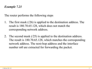
Example 7.21
The router performs the following steps
1. The first mask (/26) is applied to the destination address. The
result is 180.70.65.128, which does not match the
corresponding network address.
2. The second mask (/25) is applied to the destination address.
The result is 180.70.65.128, which matches the corresponding
network address. The next-hop address and the interface
number m0 are extracted for forwarding the packet.
- 115.
© McGraw Hill,LLC 115
Address Aggregation
When we use classful addressing, there is only one entry in the
forwarding table for each site outside the organization. The entry
defines the site even if that site is subnetted. When a packet arrives
at the router, the router checks the corresponding entry and
forwards the packet accordingly. When we use classless
addressing, it is likely that the number of forwarding table entries
will increase. To alleviate the problem, the idea of address
aggregation was designed. In Figure 7.34 we have two routers.
- 116.
© McGraw Hill,LLC 116
Figure 7.34 Address aggregation
Access the text alternative for slide images.
- 117.
© McGraw Hill,LLC 117
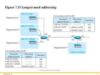
Figure 7.35 Longest mask addressing
Access the text alternative for slide images.
- 118.
© McGraw Hill,LLC 118
Example 7.22
As an example of hierarchical routing, let us consider . A regional
ISP is granted 16,384 addresses starting from 120.14.64.0. The
regional ISP has decided to divide this block into 4 subblocks, each
with 4096 addresses. Three of these subblocks are assigned to three
local ISPs, the second subblock is reserved for future use. Note that
the mask for each block is /20 because the original block with
mask /18 is divided into 4 blocks.
- 119.
© McGraw Hill,LLC 119
Figure 7.36 Hierarchical routing with ISPs
Access the text alternative for slide images.
- 120.
© McGraw Hill,LLC 120
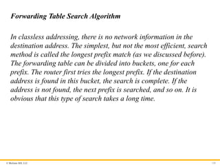
Forwarding Table Search Algorithm
In classless addressing, there is no network information in the
destination address. The simplest, but not the most efficient, search
method is called the longest prefix match (as we discussed before).
The forwarding table can be divided into buckets, one for each
prefix. The router first tries the longest prefix. If the destination
address is found in this bucket, the search is complete. If the
address is not found, the next prefix is searched, and so on. It is
obvious that this type of search takes a long time.
- 121.
© McGraw Hill,LLC 121
Forwarding Based on Label
In the 1980s, an effort started to somehow change IP to behave like
a connection-oriented protocol in which the routing is replaced by
switching. As we discussed earlier in the chapter, in a
connectionless network (datagram approach), a router forwards a
packet based on the destination address in the header of the packet.
On the other hand, in a connection-oriented network (virtual-
circuit approach), a switch forwards a packet based on the label
attached to the packet. Routing is normally based on searching the
contents of a table; switching can be done by accessing a table
using an index. In other words, routing involves searching;
switching involves accessing.
- 122.
© McGraw Hill,LLC 122
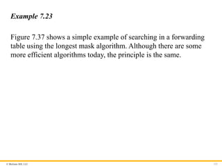
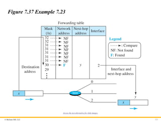
Example 7.23
Figure 7.37 shows a simple example of searching in a forwarding
table using the longest mask algorithm. Although there are some
more efficient algorithms today, the principle is the same.
- 123.
© McGraw Hill,LLC 123
Figure 7.37 Example 7.23
Access the text alternative for slide images.
- 124.
© McGraw Hill,LLC 124
Example 7.24
Figure 7.38 shows a simple example of using a label to access a
switching table. Since the labels are used as the index to the table,
finding the information in the table is immediate.
- 125.
© McGraw Hill,LLC 125
Figure 7.38 Example 7.24
Access the text alternative for slide images.
- 126.
© McGraw Hill,LLC 126
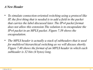
A New Header
• To simulate connection-oriented switching using a protocol like
IP, the first thing that is needed is to add a field to the packet
that carries the label discussed later. The IPv4 packet format
does not allow this extension The solution is to encapsulate the
IPv4 packet in an MPLS packet. Figure 7.39 shows the
encapsulation.
• The MPLS header is actually a stack of subheaders that is used
for multilevel hierarchical switching as we will discuss shortly.
Figure 7.40 shows the format of an MPLS header in which each
subheader is 32 bits (4 bytes) long.
- 127.
- 128.
© McGraw Hill,LLC 128
Figure 7.40 MPLS header made of a stack of labels
Access the text alternative for slide images.
- 129.
© McGraw Hill,LLC 129
Hierarchical Switching
A stack of labels in MPLS allows hierarchical switching. This is
similar to conventional hierarchical routing. For example, a packet
with two labels can use the top label to forward the packet through
switches outside an organization; the bottom label can be used to
route the packet inside the organization to reach the destination
subnet.
- 130.
© McGraw Hill,LLC 130
7.4.7 Routers as Packet Switches
A stack of labels in MPLS allows hierarchical switching. This is
similar to conventional hierarchical routing. For example, a packet
with two labels can use the top label to forward the packet through
switches outside an organization; the bottom label can be used to
route the packet inside the organization to reach the destination
subnet.
- 131.
© McGraw Hill,LLC 131
7.5 NEXT GENERATION IP (IPv6)
The address depletion of IPv4 and other shortcoming of this
protocol prompted a new version of IP protocol in the early
1990s, which is called Internet Protocol version 6 (IPv6) or
IP new generation (Ipng).
- 132.
© McGraw Hill,LLC 132
7.5.1 IPv6 Addressing
The main reason for migration from IPv4 to IPv6 was the small
size of the address space of IPv4. An IPv6 address is 128 bytes or
16 bytes, four times the address length in IPv4.
- 133.
© McGraw Hill,LLC 133
Representation
An IPv6 address is 128 bits or 16 bytes long; four times the address
length of IPv4.
Binary (128 bits) 11111110111101101011 …
1111111100000000
Colon hexadecimal FEF6:BA98:7654:3210:ADEF:BBFF:2922:FF00
- 134.
© McGraw Hill,LLC 134
Address Space2
The address space of IPv6 contains 2128
addresses. This address
space is 296
times the IPv4 address—definitely no address depletion
—as shown, the size of the space is
340, 282, 366, 920, 938, 463, 374, 607, 431, 768, 211, 456
- 135.
© McGraw Hill,LLC 135
Address Space Allocation
Like the address space of IPv4, the address space of IPv6 is divided
into several blocks of varying size and each block is allocated for a
special purpose. Most of the blocks are still unassigned and have
been set aside for future use. Table 7.5 shows only the assigned
blocks. In this table, the last column shows the fraction each block
occupies in the whole address space.
- 136.
© McGraw Hill,LLC 136
Table 7.5 Prefixes for assigned IPv6 addresses
Block prefix CIDR Block assignment Fraction
0000 0000 0000::/8 Special addresses 1/256
001 2000::/3 Global unicast 1/8
1111 110 FC00::/7 Unique local unicast 1/128
1111 1110 10 FE80::/10 Link local addresses 1/1024
1111 1111 FF00::/8 Multicast addresses 1/256
- 137.
© McGraw Hill,LLC 137
Figure 7.41 Global unicast address
Access the text alternative for slide images.
- 138.
© McGraw Hill,LLC 138
Figure 7.42 Mapping EUI-64
Access the text alternative for slide images.
- 139.
© McGraw Hill,LLC 139
Figure 7.43 Mapping for Ethernet MAC
Access the text alternative for slide images.
- 140.
© McGraw Hill,LLC 140
Example 7.25
An organization is assigned the block 2000:1456:2474/48. What is
the CIDR notation for the blocks in the first and second subnets in
this organization.
Solution
Theoretically, the first and second subnets should use the block
with subnet identifier 16 16
0001 and 0002 . This means that the
blocks are
2000:1456:2474:0000/64
and
2000:1456:2474:0001/64.
- 141.
© McGraw Hill,LLC 141
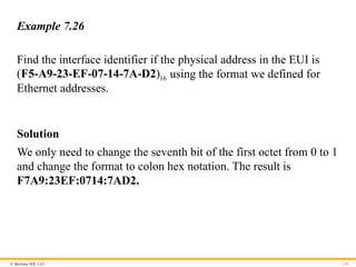
Example 7.26
Find the interface identifier if the physical address in the EUI is
16
( )
F5-A9-23-EF-07-14-7A-D2 using the format we defined for
Ethernet addresses.
Solution
We only need to change the seventh bit of the first octet from 0 to 1
and change the format to colon hex notation. The result is
F7A9:23EF:0714:7AD2.
- 142.
© McGraw Hill,LLC 142
Example 7.27
Find the interface identifier if the Ethernet physical address is
16
( )
F5-A9-23-14-7A-D2 using the format we defined for Ethernet
addresses.
Solution
We only need to change the seventh bit of the first octet from 0 to
1, insert two octet FFFE16 and change the format to colon hex
notation. The result is F7A9:23FF:FE14:7AD2 in colon hex.
- 143.
© McGraw Hill,LLC 143
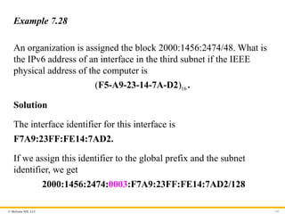
Example 7.28
An organization is assigned the block 2000:1456:2474/48. What is
the IPv6 address of an interface in the third subnet if the IEEE
physical address of the computer is
16
( )
F5-A9-23-14-7A-D2 .
Solution
The interface identifier for this interface is
F7A9:23FF:FE14:7AD2.
If we assign this identifier to the global prefix and the subnet
identifier, we get
2000:1456:2474:0003:F7A9:23FF:FE14:7AD2/128
- 144.
© McGraw Hill,LLC 144
Special Addresses
After discussing the global unicast block, let us discuss the
characteristics and purposes of assigned and reserved blocks in the
first row of Table 7.5. Addresses that use the prefix (0000::/8) are
reserved, but part of this block is used to define some special
addresses. Figure 7.44 shows the assigned addresses in this block.
- 145.
© McGraw Hill,LLC 145
Figure 7.44 Special addresses
Access the text alternative for slide images.
- 146.
© McGraw Hill,LLC 146
Other Assigned Blocks
IPv6 uses two large blocks for private addressing and one large
block for multicasting, as shown in Figure 7.45.
- 147.
© McGraw Hill,LLC 147
Figure 7.45 Unique local unicast block
Access the text alternative for slide images.
- 148.
© McGraw Hill,LLC 148
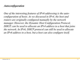
Autoconfiguration
One of the interesting features of IPv6 addressing is the auto-
configuration of hosts. As we discussed in IPv4, the host and
routers are originally configured manually by the network
manager. However, the Dynamic Host Configuration Protocol,
DHCP, can be used to allocate an IPv4 address to a host that joins
the network. In IPv6, DHCP protocol can still be used to allocate
an IPv6 address to a host, but a host can also configure itself.
- 149.
© McGraw Hill,LLC 149
Example 7.29(1)
Assume a host with Ethernet address 16
( )
F5-A9-23-11-9B-E2 has
joined the network. What would be its global unicast address if the
global unicast prefix of the organization is 3A21:1216:2165 and
the subnet identifier is A245:1232.
Solution
The host first creates its interface identifier as
F7A9:23FF:FE11:9BE2 using the Ethernet address read from its
card. The host then creates its link-local address as
FE80::F7A9:23FF:FE11:9BE2
- 150.
© McGraw Hill,LLC 150
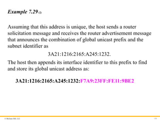
Example 7.29(2)
Assuming that this address is unique, the host sends a router
solicitation message and receives the router advertisement message
that announces the combination of global unicast prefix and the
subnet identifier as
3A21:1216:2165:A245:1232.
The host then appends its interface identifier to this prefix to find
and store its global unicast address as:
3A21:1216:2165:A245:1232:F7A9:23FF:FE11:9BE2
- 151.
© McGraw Hill,LLC 151
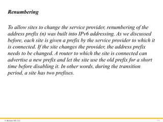
Renumbering
To allow sites to change the service provider, renumbering of the
address prefix (n) was built into IPv6 addressing. As we discussed
before, each site is given a prefix by the service provider to which it
is connected. If the site changes the provider, the address prefix
needs to be changed. A router to which the site is connected can
advertise a new prefix and let the site use the old prefix for a short
time before disabling it. In other words, during the transition
period, a site has two prefixes.
- 152.
© McGraw Hill,LLC 152
7.5.2 The IPv6 Protocol
The change of the IPv6 address size requires the change in the IPv4
packet format. The designer of IPv6 decided to implement remedies
for other shortcomings now that a change is inevitable. The
following shows other changes implemented in the protocol in
addition to changing address size and format.
- 153.
© McGraw Hill,LLC 153
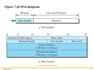
Packet Format
The IPv6 packet is shown in Figure 7.46. Each packet is composed
of a base header followed by the payload. The base header
occupies 40 bytes, whereas payload can be up to 65,535 bytes of
information. The description of fields follows.
- 154.
© McGraw Hill,LLC 154
Figure 7.46 IPv6 datagram
Access the text alternative for slide images.
- 155.
© McGraw Hill,LLC 155
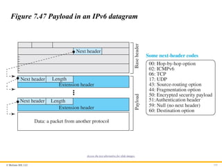
Figure 7.47 Payload in an IPv6 datagram
Access the text alternative for slide images.
- 156.
© McGraw Hill,LLC 156
Concept of Flow and Priority in IPv6
The IP protocol was originally designed as a connectionless
protocol. However, the tendency is to use the IP protocol as a
connection-oriented protocol. The MPLS technology described
earlier allows us to encapsulate an IPv4 packet in an MPLS header
using a label field. In version 6, the flow label has been directly
added to the format of the IPv6 datagram to allow us to use IPv6
as a connection-oriented protocol.
- 157.
© McGraw Hill,LLC 157
Fragmentation and Reassembly
There is still fragmentation and reassembly of datagrams in the
IPv6 protocol, but there is a major difference in this respect. IPv6
datagrams can be fragmented only by the source, not by the
routers; the reassembly takes place at the destination.
- 158.
© McGraw Hill,LLC 158
Extension Header
An IPv6 packet is made of a base header and some extension
headers. The length of the base header is fixed at 40 bytes.
However, to give more functionality to the IP datagram, the base
header can be followed by up to six extension headers. Many of
these headers are options in IPv4. Six types of extension headers
have been defined. These are hop-by-hop option, source routing,
fragmentation, authentication, encrypted security payload, and
destination option (see Figure 7.48).
- 159.
- 160.
© McGraw Hill,LLC 160
Comparison of Options (IPv4 and IPv6)1
The following shows a quick comparison between the options used
in IPv4 and the options used in IPv6.
• The no-operation and end-of-option options are replaced by Pad1 and
PadN.
• The record route option is not implemented in IPv6 because it was not used.
• The timestamp option is not implemented because it was not used.
• The source route option is called the source route extension header in IPv6.
- 161.
© McGraw Hill,LLC 161
Comparison of Options (IPv4 and IPv6)2
The following shows a quick comparison between the options used
in IPv4 and the options used in IPv6.
• The fragmentation fields in the base header section of IPv4 have moved to
the fragmentation extension header in IPv6.
• The authentication extension header is new in IPv6.
• The encrypted security payload extension header is new in IPv6.
- 162.
© McGraw Hill,LLC 162
7.5.3 The ICMPv6 Protocol
Another protocol that has been modified in version 6 of the TCP/IP
protocol suite is ICMP. This new version, ICMPv6, follows the
same strategy and purposes of version 4. ICMPv6, however, is
more complicated than ICMPv4: some protocols that were
independent in version 4 are now part of ICMPv6 and some new
messages have been added to make it more useful.
- 163.
© McGraw Hill,LLC 163
Figure 7.49 Comparison of network layer in version 4 and
version 6
Access the text alternative for slide images.
- 164.
© McGraw Hill,LLC 164
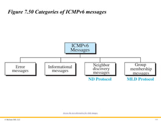
Figure 7.50 Categories of ICMPv6 messages
Access the text alternative for slide images.
- 165.
© McGraw Hill,LLC 165
Error-Reporting Messages
As we saw in our discussion of version 4, one of the main
responsibilities of ICMPv6 is to report errors. Four types of errors
are handled: destination unreachable, packet too big, time
exceeded, and parameter problems. Note that the source-quenched
message, which is used to control congestion in version 4, is
eliminated in this version because the priority and flow label fields
in IPv6 are supposed to take care of congestion.
- 166.
© McGraw Hill,LLC 166
Neighbor-Discovery Messages
Several messages in ICMPv4 have been redefined in ICMPv6 to
handle the issue of neighbor discovery. Some new messages have
also been added to provide extension. The most important issue is
the definition of two new protocols that clearly define the
functionality of these group messages: the Neighbor-Discovery
(ND) protocol and the Inverse-Neighbor-Discovery (IND) protocol.
- 167.
© McGraw Hill,LLC 167
Group Membership Messages
The management of multicast delivery handling in IPv4 is given to
the IGMPv3 protocol. In IPv6, this responsibility is given to the
Multicast Listener Delivery protocol. MLDv1 is the counterpart to
IGMPv2; MLDv2 is the counterpart to IGMPv3. The
material discussed in this section is taken from RFC 3810. The idea
is the same as we discussed in IGMPv3, but the sizes and formats
of the messages have been changed to fit the larger multicast
address size in IPv6. Like IGMPv3, MLDv2 has two types of
messages: membership-query message and membership-report
message.
- 168.
© McGraw Hill,LLC 168
7-6 TRANSITION FROM IPv4 TO IPv6
Although we have a new version of the IP protocol, how can we
make the transition to stop using IPv4 and start using IPv6? in the
Internet can move The transition must be smooth to prevent any
problems between IPv4 and IPv6 systems.
- 169.
© McGraw Hill,LLC 169
7.6.1 Strategies
Three strategies have been devised for transition: dual stack,
tunneling, and header translation. One or all of these three
strategies can be implemented during the transition period.
- 170.
© McGraw Hill,LLC 170
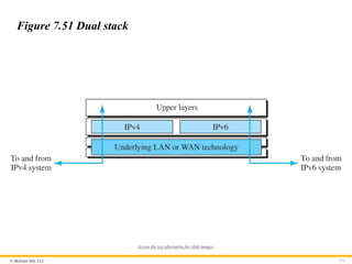
Dual Stack
It is recommended that all hosts, before migrating completely to
version 6, have a dual stack of protocols during the transition. In
other words, a station must run IPv4 and IPv6 simultaneously until
all the Internet uses IPv6. See Figure 7.51 for the layout of a dual-
stack configuration
- 171.
© McGraw Hill,LLC 171
Figure 7.51 Dual stack
Access the text alternative for slide images.
- 172.
© McGraw Hill,LLC 172
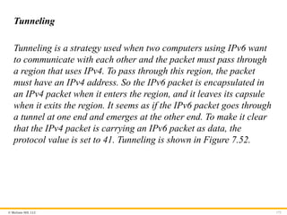
Tunneling
Tunneling is a strategy used when two computers using IPv6 want
to communicate with each other and the packet must pass through
a region that uses IPv4. To pass through this region, the packet
must have an IPv4 address. So the IPv6 packet is encapsulated in
an IPv4 packet when it enters the region, and it leaves its capsule
when it exits the region. It seems as if the IPv6 packet goes through
a tunnel at one end and emerges at the other end. To make it clear
that the IPv4 packet is carrying an IPv6 packet as data, the
protocol value is set to 41. Tunneling is shown in Figure 7.52.
- 173.
© McGraw Hill,LLC 173
Figure 7.52 Tunneling strategy
Access the text alternative for slide images.
- 174.
© McGraw Hill,LLC 174
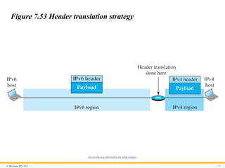
Header Translation
Header translation is necessary when the majority of the Internet
has moved to IPv6 but some systems still use IPv4. The sender
wants to use IPv6, but the receiver does not understand IPv6.
Tunneling does not work in this situation because the packet must
be in the IPv4 format to be understood by the receiver. In this case,
the header format must be totally changed through header
translation. The header of the IPv6 packet is converted to an IPv4
header (see Figure 7.53).
- 175.
© McGraw Hill,LLC 175
Figure 7.53 Header translation strategy
Access the text alternative for slide images.
- 176.
Because learning changeseverything.®
www.mheducation.com
End of Main Content
© 2022 McGraw Hill, LLC. All rights reserved. Authorized only for instructor use in the classroom.
No reproduction or further distribution permitted without the prior written consent of McGraw Hill, LLC.