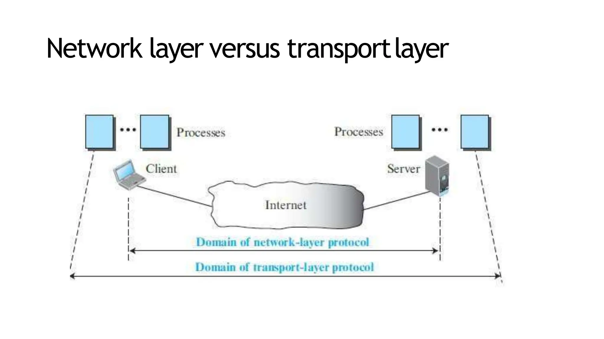
SlideShare a Scribd company logo
1 of 119
Module2
Transport Layer
Transport Layer
• The transport layer in the TCP/IP suite is located
between the application layer and the network layer.
• It provides services to the application layer and receives
services from the network layer.
• The transport layer acts as a liaison between a client program
and a server program, a process-to-process connection.
• The transport layer is the heart of the TCP/IP protocol suite;
• it is the end-to-end logical vehicle for transferring data from
one point to another in the Internet.
Transport-Layer Services
• Process-to-Process
Communication
• Addressing: Port Numbers
• Encapsulation and
Decapsulation
• Multiplexing and Demultiplexing
• Flow Control
• Error Control
• Congestion Control
process-to-process communication
• The first duty of a transport-layer protocol is to provide
process-to- process communication.
• A process is an application-layer entity (running program) that
uses the services of the transport layer.
• A process on the local host, called a client, needs services
from a process usually on the remote host, called a server.
• Both processes (client and server) have the same name.
Difference between host-to-host communication
and process-to-process communication
• The network layer is responsible for communication at the computer
level (host-to-host communication).
• A network-layer protocol can deliver the message only to the
destination computer.
• The message still needs to be handed to the correct process. This
is done by transport-layer protocol.
• A transport-layer protocol is responsible for delivery of the message
to the appropriate process.
• The destination IP address defines the host among the different
hosts in the world.
• After the host has been selected, the port number defines one
of the processes on this particular host.
Network layer versus transportlayer
Addressing: PortNumbers
• For communication, we must define the local host, local process,
remote host, and remote process.
• The local host and the remote host are defined using IP addresses .
• To define the processes, we need second identifiers, called port
numbers.
• In the TCP/IP protocol suite, the port numbers are integers between
0 and 65,535 (16 bits).
• The client program defines itself with a port number, called the
ephemeral port number.
• The word ephemeral means short-lived and is used because the
life of a client is normally short.
• An ephemeral port number is recommended to be greater than
• The server process must also define itself with a port number.
• This port number cannot be chosen randomly.
• TCP/IP has decided to use universal port numbers for servers;
these are called well-known port numbers.
• ICANN has divided the port numbers into three ranges: well-
known, registered, and dynamic (or private).
• The ports ranging from 0 to 1,023 are assigned and
controlled by ICANN. These are the well-known ports.
• The ports ranging from 1,024 to 49,151 are not assigned or
controlled by ICANN. They can only be registered with ICANN
to prevent duplication.
• The ports ranging from 49,152 to 65,535 are neither controlled
nor registered. They can be used as temporary or private port
numbers.
Encapsulation andDecapsulation
• To send a message from one process to another, the
transport-layer protocol encapsulates and decapsulates
messages.
• Encapsulation happens at the sender site.
• When a process has a message to send, it passes the
message to the transport layer along with a pair of socket
addresses and some other pieces of information, which
depend on the transport-layer protocol.
• The transport layer receives the data and adds the transport-
layer header.
• The packets at the transport layers in the Internet are called
user datagrams, segments, or packets, depending on what
transport-layer protocol we use.
• Decapsulation happens at the receiver site.
• When the message arrives at the destination transport layer, the
header is dropped and the transport layer delivers the message
to the process running at the application layer.
• The sender socket address is passed to the process in case it
needs to respond to the message received.
Multiplexing andDemultiplexing
• Whenever an entity accepts items from more than one source,
this is referred to as multiplexing (many to one);
• whenever an entity delivers items to more than one source,
this is referred to as demultiplexing (one to many).
• The transport layer at the source performs multiplexing; the
transport layer at the destination performs demultiplexing.
• Although there is only one message, we use demultiplexer.
Flow Control
• If the items are produced faster than they can be consumed, the
consumer can be overwhelmed and may need to discard some
items.
• Flow control is related to this issue.
• We need to prevent losing the data items at the consumer site.
• If the sender delivers items whenever they are produced without a
prior request from the consumer⎯the delivery is referred to as
pushing.
• If the producer delivers the items after the consumer has requested
them, the delivery is referred to as pulling.
• When the producer pushes the items, the consumer may be
overwhelmed and there is a need for flow control, in the opposite
direction, to prevent discarding of the items.
• we need at least two cases of flow control: from the sending
transport layer to the sending application layer and from the
receiving transport layer to the sending transport layer.
• One of the solutions is normally to use two buffers: one at the
sending transport layer and the other at the receiving transport
layer.
• A buffer is a set of memory locations that can hold packets
at the sender and receiver.
• The flow control communication can occur by sending signals
from the consumer to the producer.
• When the buffer of the sending transport layer is full, it informs
the application layer to stop passing chunks of messages;
when there are some vacancies, it informs the application layer
that it can pass message chunks again.
• When the buffer of the receiving transport layer is full, it informs
the sending transport layer to stop sending packets. When there
are some vacancies, it informs the sending transport layer that it
can send packets again.
Error Control
• In the Internet, since the underlying network layer (IP) is
unreliable, we need to make the transport layer reliable if the
application requires reliability.
• Reliability can be achieved to add error control services
to the transport layer.
• Error control at the transport layer is responsible for
• 1. Detecting and discarding corrupted packets.
• 2. Keeping track of lost and discarded packets and resending
them.
• 3. Recognizing duplicate packets and discarding them.
• 4. Buffering out-of-order packets until the missing packets
arrive.
• We can add a field to the transport-layer packet to hold the
sequence number of the packet.
• When a packet is corrupted or lost, the receiving transport
layer can somehow inform the sending transport layer to
resend that packet using the sequence number.
• For error control, the sequence numbers are modulo 2m,
where m is the size of the sequence number field in bits.
• The receiver side can send an acknowledgment (ACK) for
each of a collection of packets.
• The sender can detect lost packets if it uses a timer.
• When a packet is sent, the sender starts a timer. If an ACK
does not arrive before the timer expires, the sender resends
the packet.
• These two requirements can be combined if we use two
numbered buffers, one at the sender, one at the receiver.
• At the sender, when a packet is prepared to be sent, we use
the number of the next free location, x, in the buffer as the
sequence number of the packet.
• When the packet is sent, a copy is stored at memory
location x, awaiting the acknowledgment from the other
end.
• When an acknowledgment related to a sent packet arrives, the
packet is purged and the memory location becomes free.
• At the receiver, when a packet with sequence number y arrives,
it is stored at the memory location y until the application layer
is ready to receive it.
• An acknowledgment can be sent to announce the arrival of
packet y.
Sliding Window
• A circle can represent the sequence numbers from 0 to 2^m − 1
• The buffer is represented as a set of slices, called the sliding window, that
occupies part of the circle at any time.
• At the sender site, when a packet is sent, the corresponding slice is marked.
• When an acknowledgment arrives, the corresponding slice is unmarked.
Congestion Control
• Congestion in a network may occur if the load on the network—the
number of packets sent to the network—is greater than the capacity
of the network—the number of packets a network can handle.
• Congestion control refers to the mechanisms and techniques that
control the congestion and keep the load below the capacity.
• Congestion in a network or internetwork occurs because routers and
switches have queues—buffers that hold the packets before
and after processing.
• A router, for example, has an input queue and an output queue for
each interface.
• If a router cannot process the packets at the same rate at
which they arrive, the queues become overloaded and
congestion occurs.
• Congestion at the transport layer is actually the result of congestion
at the network layer.
Principles of CongestionControl
• A TCP sender can also be throttled due to congestion within
the IP network; this form of sender control is referred to as
congestion control.
• Specific TCP mechanisms are used to provide for a
reliable data transfer service in the face of packet loss.
• Such loss typically results from the overflowing of router
buffers as the network becomes congested.
• Packet retransmission thus treats a symptom of network
congestion (the loss of a specific transport-layer segment) but
does not treat the cause of network congestion.
Scenario:TwoSendersand a Routerwith
FiniteBuffers
• The amount of router buffering is assumed to be finite.
• A consequence of this real-world assumption is that
packets will be dropped when arriving to an already
fullbuffer.
• Second, we assume that each connection is reliable.
If a packet containing a transport-level segment is
dropped at the router, the sender will eventually
retransmit it.
Scenario:Four Senders,Routers withFinite
Buffers, and MultihopPaths
• Each host uses a timeout/retransmission mechanism to
implement a reliable data transfer service, that all hosts
have the same value of Yin, and that all router links
have capacity R bytes/sec.
• In the high-traffic scenario, whenever a packet is
dropped at a second-hop router, the work done by the
first-hop router in forwarding a packet to the second-hop
router ends up being “wasted.”
Approaches to CongestionControl
• End-to-end congestion control
• Network-assisted congestion
control.
End-to-end congestion control.
• The network layer provides no explicit support to the transport
layer for congestion control purposes.
• Even the presence of congestion in the network must be
inferred by the end systems based only on observed network
behaviour.
• TCP must necessarily take this end-to- end approach toward
congestion control, since the IP layer provides no feedback to
the end systems regarding network congestion.
• TCP segment loss (as indicated by a timeout or a triple
duplicate acknowledgment) is taken as an indication of network
congestion and TCP decreases its window size accordingly.
Network-assisted congestion control.
• The network-layer components (that is, routers) provide explicit
feedback to the sender regarding the congestion state in the
network.
• This feedback may be as simple as a single bit indicating
congestion at a link.
• Direct feedback may be sent from a network router to the
sender. This form of notification typically takes the form of a
choke packet (essentially saying, “I’m congested!”).
• The second form of notification occurs when a router
marks/updates a field in a packet flowing from sender to
receiver to indicate congestion.
• Upon receipt of a marked packet, the receiver then
notifies the sender of the congestion indication.
Network-Assisted Congestion-ControlExample:
ATM ABR CongestionControl
• A protocol that takes a network-assisted approach toward
congestion control.
• Asynchronous Transfer Mode Available Bit-Rate
• ATM ABR congestion control is a rate-based approach.
• That is, the sender explicitly computes a maximum rate at
which it can send and regulates itself accordingly.
• ABR provides three mechanisms for signaling congestion-
related information from the switches to the receiver:
• EFCI bit. Each data cell contains an explicit
forward congestion indication (EFCI) bit. A
congested network switch can set the EFCI bit in
a data cell to 1 to signal congestion to the
destination host.
• congestion indication (CI) bit and a no increase (NI)
bit that can be set by a congested network switch.
• explicit rate (ER) field. A congested switch may
lower the value contained in the ER field in a
passing packet.
TCP/IP Protocol
Suite
12
CONGESTION CONTROL
TCP uses a congestion window and a congestion policy that avoid
congestion and detect and alleviate congestion after it has
occurred.
CongestionWindow
• The sender window size is determined by the available buffer
space in the receiver (rwnd).
• It is only the receiver that can dictate to the sender the size of
the sender’s window.
CongestionWindow
• If the network cannot deliver the data as fast as it is created by
the sender, it must tell the sender to slow down.
• In other words, in addition to the receiver, the network is a
second entity that determines the size of the sender’s window.
CongestionWindow
• The sender has two pieces of information:
 the receiver-advertised window size
 and the congestion window size.
• The actual size of the window is the minimum of these
two.
• Actual window size = minimum (rwnd, cwnd)
CongestionPolicy
• TCP’s general policy for handling congestion is based on three
phases:
• Slow start, congestion avoidance, and congestion detection.
• In the slow start phase, the sender starts with a slow
transmission, but increases the rate rapidly to reach a
threshold.
• When the threshold is reached, the rate of increase is
reduced.
rate of
• Finally if ever congestion is detected, the sender goes back to the
slow start or congestion avoidance phase, based on how the
congestion is detected.
Slow Start:ExponentialIncrease
• The slow start algorithm is based on the idea that the size of the
congestion window (cwnd) starts with one maximum segment size
(MSS).
• The MSS is determined during connection establishment using an
option of the same name.
• The size of the window increases one MSS each time one
acknowledgement arrives.
• As the name implies, the algorithm starts slowly, but grows
exponentially.
TCP/IP Protocol
Suite
18
Figure 15.34 Slow start, exponential increase
Slow start, exponential increase
Congestion Avoidance: AdditiveIncrease
• If we start with the slow start algorithm, the size of the congestion
window increases exponentially.
• To avoid congestion before it happens, one must slow down this
exponential growth.
• TCP defines another algorithm called congestion avoidance, which
increases the cwnd additively instead of exponentially.
TCP/IP Protocol
Suite
21
Figure 15.35 Congestion avoidance, additive increase
Congestion Avoidance: AdditiveIncrease
Congestion Detection: MultiplicativeDecrease
• If congestion occurs, the congestion window size must be
decreased.
• The only way a sender can guess that congestion has occurred is
the need to retransmit a segment.
• This is a major assumption made by TCP.
• Retransmission is needed to recover a missing packet which is assumed to
have been dropped (i.e., lost) by a router that had so many incoming
packets, that had to drop the missing segment, i.e., the router/network
became overloaded or congested.
• However, retransmission can occur in one of two cases:
• when the RTO timer times out or
• when three duplicate ACKs are received.
• In both cases, the size of the threshold is dropped to half (multiplicative decrease).
1. If a time-out occurs, there is a stronger possibility of
congestion; a segment has probably been dropped in the
network and there is no news about the following sent segments.
In this case TCP reacts strongly:
a.It sets the value of the threshold to half of the current window
size.
b. It reduces cwnd back to one segment.
c.It starts the slow start phase again.
2. If three duplicate ACKs are received, there is a weaker
possibility of congestion; a segment may have been dropped but
some segments after that have arrived safely since three duplicate
ACKs are received. This is called fast transmission and fast recovery.
In this case, TCP has a weaker reaction as shownbelow:
a. It sets the value of the threshold to half of the current window size.
b.It sets cwnd to the value of the threshold (some implementations add
three segment sizes to the threshold).
c. It starts the congestion avoidance phase.
ConnectionlessandConnection-Oriented Services
• Connectionless service at the transport layer means
independency between packets;
• Connection-oriented means dependency.
ConnectionlessService
• In a connectionless service, the source process (application program)
needs to divide its message into chunks of data of the size acceptable
by the transport layer and deliver them to the transport layer one by
one.
• When a chunk arrives from the application layer, the transport
layer encapsulates it in a packet and sends it.
• Assume that a client process has three chunks of messages to
send to a server process.
• The chunks are handed over to the connectionless transport
protocol in order.
• However, since there is no dependency between the packets at the
transport layer, the packets may arrive out of order at the destination
and will be delivered out of order to the server process.
• If these three chunks of data belong to the same message, the
server process may have received a strange message.
• Since there is no numbering on the packets, the receiving
transport layer has no idea that one of the messages has
been lost.
• no flow control, error control, or congestion control can be
effectively implemented in a connectionless service.
Connection-OrientedService
• The client and the server first need to establish a logical
connection between themselves.
• The data exchange can only happen after the
connection establishment.
• After data exchange, the connection needs to be turn down.
• We can implement flow control, error control, and congestion
control in a connection oriented protocol.
PROTOCOLSFORRELIABLEDATATRANSFER
• Simple Protocol
• Stop-and-Wait Protocol
• Go-Back-N Protocol
(GBN)
• Selective-Repeat
Protocol
SimpleProtocol
StatesofSimpleProtocol
Stop-and-WaitProtocol
• It is a connection-oriented protocol, which uses both flow and error
control.
• Both the sender and the receiver use a sliding window of size 1.
• The sender sends one packet at a time and waits for an
acknowledgment before sending the next one.
• To detect corrupted packets, we need to add a checksum to
each data packet.
• When a packet arrives at the receiver site, it is checked. If its
checksum is incorrect, the packet is corrupted and silently
discarded.
• Every time the sender sends a packet, it starts a timer. If the timer
expires, the sender resends the previous packet.
• To prevent duplicate packets, the protocol uses sequence
numbers and acknowledgment numbers.
• In the Stop-and-Wait protocol, the acknowledgment number
always announces, in modulo-2 arithmetic, the sequence
number of the next packet expected.
• The new packet is x + 1, not x + 2. If only x and x + 1 are needed
let x = 0 and x + 1 = 1.
• This means that the sequence is 0, 1, 0, 1, 0, and so on. This is
referred to as modulo 2 arithmetic.
• The Stop-and-Wait protocol is very inefficient if our channel has a
large bandwidth and the round-trip delay is long .
• The product of these two is called the bandwidth delay product.
• The bandwidth-delay product is a measure of the number of bits a
sender can transmit through the system while waiting for an
acknowledgment from the receiver.
• There is no pipelining in the Stop-and-Wait protocol because a
sender must wait for a packet to reach the destination and be
acknowledged before the next packet can be sent.
Go-Back-NProtocol(GBN)
• The key to Go-back-N is that we can send several packets
before receiving acknowledgments, but the receiver can
only buffer one packet.
• We keep a copy of the sent packets until the acknowledgments
arrive.
• several data packets and acknowledgments can be in the
channel at the same time.
• if the acknowledgment number (ackNo) is 7, it means all
packets with sequence number up to 6 have arrived, safe and
sound, and the receiver is expecting the packet with sequence
number 7.
• This protocol is inefficient if the underlying network protocol
loses a lot of packets.
• Each time a single packet is lost or corrupted, the sender
resends all outstanding packets, even though some of these
packets may have been received safe and sound but out of
order.
• If the network layer is losing many packets because of
congestion in the network, the resending of all of these
outstanding packets makes the congestion worse, and
eventually more packets are lost.
• This has an avalanche effect that may result in the total
collapse of the network.
Selective-RepeatProtocol
• It resends only selective packets, those that are actually lost.
• The Selective-Repeat protocol uses two windows: a send
window and a receive window.
• The receive window is the same size as the send window.
• ackNo defines the sequence number of one single packet
that is received safe and sound.
BidirectionalProtocols:Piggybacking
• In real life, data packets are normally flowing in both directions:
from client to server and from server to client.
• This means that acknowledgments also need to flow in
both directions.
• A technique called piggybacking is used to improve the
efficiency of the bidirectional protocols.
• When a packet is carrying data from A to B, it can also
carry acknowledgment feedback about arrived
packets from B.
InternetTransport-LayerProtocols
• Although the Internet uses several transport-layer
protocols, we discuss only two : UDP and TCP
• These protocols are located between the application layer and
the network layer and serve as the intermediary between the
application programs and the network operations.
• UDP is an unreliable connectionless transport-layer protocol
used for its simplicity and efficiency in applications where error
control can be provided by the application-layer process.
• TCP is a reliable connection-oriented protocol that can be used
in any application where reliability is important.
• Both are responsible to create a process-to-process
communication
UDP does just about as little as a transport protocol can do.
Aside from the multiplexing/demultiplexing function and
some light error checking, it adds nothing to IP.
UDP takes messages from the application process, attaches
source and destination port number fields for the
multiplexing/demultiplexing service, adds two other small
fields, and passes the resulting segment to the network
layer.
The network layer encapsulates the transport-
layer segment into an IP datagram and then
makes a best-effort attempt to deliver the segment
to the receiving host.
If the segment arrives at the receiving host, UDP uses the
destination port number to deliver the segment’s data to
the correct application process.
Note that with UDP there is no handshaking between
sending and receiving transport-layer entities before
sending a segment. For this reason, UDP is said to be
connectionless.
Many applications are better suited for
UDP for the following reasons:
1. application-level control over what data is sent, and when.
2. No connection establishment-UDP does not introduce any
delay to establish a connection. This is probably the principal
reason why DNS runs over UDP rather than TCP.
3. No connection state.
4. Small packet header overhead. The TCP segment has 20
bytes of header overhead in every segment, whereas UDP has
only 8 bytes of overhead.
Explanation
application-level control over what data is sent, and when
an application process passes data to UDP, UDP will package
the data inside a UDP segment and immediately pass the
segment to the network layer.
TCP, on the other hand, has a congestion-control
mechanism that throttles the transport-layer TCP sender.
TCP will also continue to resend a segment until the receipt
of the segment has been acknowledged by the destination,
regardless of how long reliable delivery takes.
Since real-time applications often require a minimum
sending rate, do not want to overly delay segment
transmission, and can tolerate some data loss, TCP’s service
model is not particularly well matched to these applications’
needs.
Explanation
No connection state
TCP maintains connection state in the end systems. This
connection state includes receive and send buffers,
congestion-control parameters, and sequence and
acknowledgment number parameters.
UDP, on the other hand, does not maintain connection state
and does not track any of these parameters. For this reason,
a server devoted to a particular application can typically
support many more active clients when the application runs
over UDP rather than TCP.
The UDP header has only four fields, each consisting of two
bytes.
The port numbers allow the destination host to pass the
application data to the correct process running on the
destination end system (that is, to perform the demultiplexing
function).
The length field specifies the number of bytes in the UDP
segment (header plus data).
An explicit length value is needed since the size of the data
field may differ from one UDP segment to the next.
The checksum is used by the receiving host to check whether
errors have been introduced into the segment.
The UDP checksum provides for error detection.
That is, the checksum is used to determine whether bits
within the UDP segment have been altered (for example, by
noise in the links or while stored in a router) as it moved
from source to destination.
UDP at the sender side performs the 1s complement of the
sum of all the 16-bit words in the segment, with any
overflow encountered during the sum being wrapped
around.
This result is put in the checksum field of the UDP segment.
0110011001100000
0101010101010101
1000111100001100
The sum of first two of these 16-bit words is
0110011001100000
0101010101010101
1011101110110101
Adding the third word to the above sum gives
1011101110110101
1000111100001100
1,0100101011000001
0100101011000001
1
-----------------------
0100101011000010
Note that this last addition had overflow, which was wrapped
around.
The 1s complement is obtained by converting all the 0s to 1s and
converting all the 1s to 0s.
Thus the 1s complement of the sum 0100101011000010 is
1011010100111101, which becomes the checksum.
At the receiver, all four 16-bit words are added, including the
checksum. If no errors are introduced into the packet, then
clearly the sum at the receiver will be 1111111111111111.
If one of the bits is a 0, then we know that errors have been
introduced into the packet.
0110011001100000
0101010101010101
1000111100001100
1011010100111101
----------------------------
1111111111111111
Message is accepted.
TRANSMISSION CONTROL PROTOCOL(TCP)
• Transmission Control Protocol (TCP) is a connection-oriented,
reliable protocol.
• TCP explicitly defines connection establishment, data
transfer, and connection teardown phases to provide a
connection-oriented service.
• TCP uses a combination of GBN and SR protocols to provide
reliablity.
• To achieve this goal, TCP uses checksum (for error detection),
retransmission of lost or corrupted packets, cumulative and
selective acknowledgments, and timers.
• TCP is the most common transport-layer protocol in the
Internet.
TCP
Services
89
TCP/IP Protocol Suite
 Process-to-Process Communication
 Stream Delivery Service
 Full-Duplex Communication
 Multiplexing and Demultiplexing
 Connection-Oriented Service
 Reliable Service
TCP segment format
90
TCP/IP Protocol Suite
• Source port address. This is a 16-bit field that defines the
port number of the application program in the host that is
sending the segment.
• Destination port address. This is a 16-bit field that defines
the port number of the application program in the host that is
receiving the segment.
• Sequence number. This 32-bit field defines the number
assigned to the first byte of data contained in this segment.
• Acknowledgment number. This 32-bit field defines the byte
number that the receiver of the segment is expecting to
receive from the other party.
• Header length. This 4-bit field indicates the number of 4-byte
words in the TCP header.
• Control. This field defines 6 different control bits or flags.
• One or more of these bits can be set at a time.
• These bits enable flow control, connection establishment and
termination, connection abortion, and the mode of data
transfer in TCP.
• Window size. This field defines the window size of the sending
TCP in bytes.The length of this field is 16 bits. This value is
normally referred to as the receiving window (rwnd) and is
determined by the receiver.
• Checksum. This 16-bit field contains the checksum. The
calculation of the checksum for TCP follows the same
procedure as the one described for UDP. However, the use of
the checksum in the UDP datagram is optional, whereas the
use of the checksum for TCP is mandatory.
• The pseudoheader is added to the segment. For the
TCP pseudo header, the value for the protocol field is 6.
• Urgent pointer. This 16-bit field, which is valid only if the
urgent flag is set, is used when the segment contains urgent
data.
• Options. There can be up to 40 bytes of optional information
in the TCP header.
Frame
header
IP
header
Figure 15.8 Encapsulation
Application-layer data
TCP
header
TCPpayload
IP payload
Data-linklayer payload
96
TCP/IP Protocol Suite
 Connection Establishment
 Data Transfer
 Connection Termination
 Connection Reset
Three phases
97
TCP/IP Protocol Suite
TCPConnectionphases
• TCP is connection-oriented.
• In TCP, connection-oriented transmission requires three
phases:
• connection establishment
• data transfer
• connection termination.
ConnectionEstablishment
• TCP transmits data in full-duplex mode.
• Each party must initialize communication and get approval
from the other party before any data are transferred.
• The connection establishment in TCP is called
three-way handshaking.
• The process starts with the server. The server program tells its
TCP that it is ready to accept a connection. This request is
called a passive open.
• The client program issues a request for an active open.
• 1. The client sends the first segment, a SYN segment, in
which only the SYN flag is set.
• This segment is for synchronization of sequence numbers.
• The SYN segment is a control segment and carries no data.
• However, it consumes one sequence number because it
needs to be acknowledged.
• 2. The server sends the second segment, a SYN + ACK
segment.
• This segment has a dual purpose. First, it is a SYN segment
for communication in the other direction. The server also
acknowledges the receipt of the SYN segment from the client
by setting the ACK flag. It also needs to define the receive
window size, rwnd (to be used by the client).
• 3. The client sends the third segment. This is just an ACK
segment. An ACK segment, if carrying no data, consumes no
DataTransfer
• After connection is established, bidirectional data transfer can
take place. The client and server can send data and
acknowledgments in both directions.
• In this example, after a connection is established, the client
sends 2,000 bytes of data in two segments. The server then
sends 2,000 bytes in one segment. The client sends one
more segment.
• The data segments sent by the client have the PSH (push)
flag set.
ConnectionTermination
• Either of the two parties involved in exchanging data (client or
server) can close the connection, although it is usually initiated
by the client.
• Most implementations today allow two options for connection
termination: three-way handshaking and four-way handshaking
with a half-close option.
• In TCP, one end can stop sending data while still receiving data.
This is called a halfclose. Either the server or the client can
issue a half-close request. It can occur when the server needs
all the data before processing can begin.
Three-WayHandshakingfortermination
• 1. In this situation, the client TCP, after receiving a close
command from the client process, sends the first segment, a
FIN segment in which the FIN flag is set.
• 2. The server TCP, after receiving the FIN segment, informs its
process of the situation and sends the second segment, a
FIN+ACK segment.
• 3. The client TCP sends the last segment, an ACK segment, to
confirm the receipt of the FIN segment from the TCP server.
Three way Handshaking for termination
Three-WayHandshakingfor termination with Half-Close
ConnectionReset
• TCP at one end may deny a connection request, may abort an
existing connection, or may terminate an idle connection.
• All of these are done with the RST (reset) flag.
Mechanisms forreliabledatatransfer
• Checksum
• Used to detect bit errors in a transmitted packet.
• Timer
• Used to timeout/retransmit a packet, possibly because the packet (or its
ACK) was lost within the channel.
• Sequence number
• Used for sequential numbering of packets of data flowing from sender to
receiver.
• Acknowledgment
• Used by the receiver to tell the sender that a packet or set of packets
has been received correctly.
• Negative acknowledgment
• Used by the receiver to tell the sender that a packet has not been received
correctly.
• Window, pipelining
• The sender may be restricted to sending only packets with sequence
numbers that fall within a given range.
ErrorControl:Alternating-bitprotocol.
• If the packet sequence numbers alternate between 0 and
1,then the protocol is known as the alternating-bit protocol.
• The operations with this protocol are:
• a. Operation with no loss
• b. Lost packet
• c. Lost ACK
• d. Premature timeout
pipelining
• The sender is allowed to send multiple packets without
waiting for acknowledgments.
• Since the many in-transit sender-to-receiver packets can be
visualized as filling a pipeline, this technique is known as
pipelining.
• Pipelining has the following consequences for reliable data
transfer protocols:
• The range of sequence numbers must be increased,
since each in- transit packet (not counting retransmissions)
must have a unique sequence number and there may be
multiple, in-transit, unacknowledged packets.
• The sender and receiver sides of the protocols may have
to buffer
more than one packet.
• A data transfer protocol responds to lost, corrupted, and
overly delayed packets.
• Two basic approaches toward pipelined error recovery
can be identified: Go-Back-N and selective repeat.
FlowcontrolinTCP
• TCP provides a flow-control service to its applications to
eliminate the possibility of the sender overflowing the
receiver’s buffer.
• Flow control is thus a speed-matching service—matching the
rate at which the sender is sending against the rate at which
the receiving application is reading.
• TCP provides flow control by having the sender maintain a
variable called the receive window.
• Informally, the receive window is used to give the sender an
idea of how much free buffer space is available at the
receiver.
• Because TCP is not permitted to overflow the allocated buffer, we
must have
• LastByteRcvd – LastByteRead <= RcvBuffer
• The receive window, denoted rwnd is set to the amount of spare
room in the buffer:
• rwnd = RcvBuffer – [LastByteRcvd – LastByteRead]
• Suppose that Host A is sending a large file to Host B
over a TCP connection.
• Host B allocates a receive buffer to this connection; denote its
size by RcvBuffer.
• Host B tells Host A how much spare room it has in the
connection buffer by placing its current value of rwnd in the
receive window field of every segment it sends to A.
• By keeping the amount of unacknowledged data less than the
value of rwnd, Host A is assured that it is not overflowing the
receive buffer at Host B.
• Thus, Host A makes sure throughout the connection’s life that
• LastByteSent – LastByteAcked <= rwnd
SYNFloodingAttack
• The connection establishment procedure in TCP is susceptible to a serious
security problem called SYN flooding attack.
• This happens when one or more malicious attackers send a large number of SYN
segments to a server pretending that each of them is coming from a different
client by faking the source IP addresses in the datagrams.
• The server, assuming that the clients are issuing an active open, allocates the
necessary resources, such as creating transfer control block (TCB) tables and
setting timers.
• The TCP server then sends the SYN + ACK segments to the fake clients, which are
lost.
• When the server waits for the third leg of the handshaking process, however,
resources are allocated without being used.
• If, during this short period of time, the number of SYN segments is large, the server
eventually runs out of resources and may be unable to accept connection requests
from valid clients.
• This SYN flooding attack belongs to a group of security attacks known as a denial of
service attack, in which an attacker monopolizes a system with so many service
requests that the system overloads and denies service to valid requests.
• Fortunately, an effective defense known as SYN cookies are now deployed in most
major operating systems.

More Related Content

Similar to Module 2.pptx.............sdvsdcdssdfsdf

Unit-4 (1).pptx
Unit-4 (1).pptxUnit-4 (1).pptx
Unit-4 (1).pptxpoonamsngr
 
UNIT-3 network security layers andits types
UNIT-3 network security layers andits typesUNIT-3 network security layers andits types
UNIT-3 network security layers andits typesgjeyasriitaamecnew
 
Computer networks unit iv
Computer networks    unit ivComputer networks    unit iv
Computer networks unit ivJAIGANESH SEKAR
 
Computer network coe351- part4- final
Computer network coe351- part4- finalComputer network coe351- part4- final
Computer network coe351- part4- finalTaymoor Nazmy
 
Unit 4-Transport Layer Protocols-3.pptx
Unit 4-Transport Layer Protocols-3.pptxUnit 4-Transport Layer Protocols-3.pptx
Unit 4-Transport Layer Protocols-3.pptxDESTROYER39
 
Unit 4-Transport Layer Protocols.pptx
Unit 4-Transport Layer Protocols.pptxUnit 4-Transport Layer Protocols.pptx
Unit 4-Transport Layer Protocols.pptxsarosh32
 
Dcn ppt by roma
Dcn ppt by romaDcn ppt by roma
Dcn ppt by romaboraroma
 
Dcn ppt on data link layer
Dcn ppt on data link layerDcn ppt on data link layer
Dcn ppt on data link layerroma bora
 
Trasport layer
Trasport layerTrasport layer
Trasport layerRAJ ANAND
 
DATA COMMUNICATION BY BP. ...
DATA COMMUNICATION BY BP.                                                    ...DATA COMMUNICATION BY BP.                                                    ...
DATA COMMUNICATION BY BP. ...BPRAVEENROLEX
 
Congestion control
Congestion controlCongestion control
Congestion controlNithin Raj
 
Traffic Characterization
Traffic CharacterizationTraffic Characterization
Traffic CharacterizationIsmail Mukiibi
 
Congestion control 1
Congestion control 1Congestion control 1
Congestion control 1Aman Jaiswal
 

Similar to Module 2.pptx.............sdvsdcdssdfsdf (20)

Transport layer
Transport layerTransport layer
Transport layer
 
Unit-4 (1).pptx
Unit-4 (1).pptxUnit-4 (1).pptx
Unit-4 (1).pptx
 
UNIT-3 network security layers andits types
UNIT-3 network security layers andits typesUNIT-3 network security layers andits types
UNIT-3 network security layers andits types
 
Computer networks unit iv
Computer networks    unit ivComputer networks    unit iv
Computer networks unit iv
 
Computer network coe351- part4- final
Computer network coe351- part4- finalComputer network coe351- part4- final
Computer network coe351- part4- final
 
Unit 4-Transport Layer Protocols-3.pptx
Unit 4-Transport Layer Protocols-3.pptxUnit 4-Transport Layer Protocols-3.pptx
Unit 4-Transport Layer Protocols-3.pptx
 
Unit 4-Transport Layer Protocols.pptx
Unit 4-Transport Layer Protocols.pptxUnit 4-Transport Layer Protocols.pptx
Unit 4-Transport Layer Protocols.pptx
 
9_Network.ppt
9_Network.ppt9_Network.ppt
9_Network.ppt
 
MODULE-4_CCN.pptx
MODULE-4_CCN.pptxMODULE-4_CCN.pptx
MODULE-4_CCN.pptx
 
Dcn ppt by roma
Dcn ppt by romaDcn ppt by roma
Dcn ppt by roma
 
Dcn ppt on data link layer
Dcn ppt on data link layerDcn ppt on data link layer
Dcn ppt on data link layer
 
Trasport layer
Trasport layerTrasport layer
Trasport layer
 
DATA COMMUNICATION BY BP. ...
DATA COMMUNICATION BY BP.                                                    ...DATA COMMUNICATION BY BP.                                                    ...
DATA COMMUNICATION BY BP. ...
 
Tcp(no ip) review part1
Tcp(no ip) review part1Tcp(no ip) review part1
Tcp(no ip) review part1
 
Congestion control
Congestion controlCongestion control
Congestion control
 
Nigga.pdf
Nigga.pdfNigga.pdf
Nigga.pdf
 
Traffic Characterization
Traffic CharacterizationTraffic Characterization
Traffic Characterization
 
Transport layer protocol
Transport layer protocolTransport layer protocol
Transport layer protocol
 
Congestion control 1
Congestion control 1Congestion control 1
Congestion control 1
 
DATA LINK LAYER.pdf
DATA LINK LAYER.pdfDATA LINK LAYER.pdf
DATA LINK LAYER.pdf
 

Recently uploaded

VIP Call Girls Kolkata Ananya 🤌 8250192130 🚀 Vip Call Girls Kolkata
VIP Call Girls Kolkata Ananya 🤌  8250192130 🚀 Vip Call Girls KolkataVIP Call Girls Kolkata Ananya 🤌  8250192130 🚀 Vip Call Girls Kolkata
VIP Call Girls Kolkata Ananya 🤌 8250192130 🚀 Vip Call Girls Kolkataanamikaraghav4
 
Complet Documnetation for Smart Assistant Application for Disabled Person
Complet Documnetation   for Smart Assistant Application for Disabled PersonComplet Documnetation   for Smart Assistant Application for Disabled Person
Complet Documnetation for Smart Assistant Application for Disabled Personfurqan222004
 
Denver Web Design brochure for public viewing
Denver Web Design brochure for public viewingDenver Web Design brochure for public viewing
Denver Web Design brochure for public viewingbigorange77
 
Call Girls In Mumbai Central Mumbai ❤️ 9920874524 👈 Cash on Delivery
Call Girls In Mumbai Central Mumbai ❤️ 9920874524 👈 Cash on DeliveryCall Girls In Mumbai Central Mumbai ❤️ 9920874524 👈 Cash on Delivery
Call Girls In Mumbai Central Mumbai ❤️ 9920874524 👈 Cash on Deliverybabeytanya
 
定制(Management毕业证书)新加坡管理大学毕业证成绩单原版一比一
定制(Management毕业证书)新加坡管理大学毕业证成绩单原版一比一定制(Management毕业证书)新加坡管理大学毕业证成绩单原版一比一
定制(Management毕业证书)新加坡管理大学毕业证成绩单原版一比一Fs
 
VIP Kolkata Call Girl Alambazar 👉 8250192130 Available With Room
VIP Kolkata Call Girl Alambazar 👉 8250192130  Available With RoomVIP Kolkata Call Girl Alambazar 👉 8250192130  Available With Room
VIP Kolkata Call Girl Alambazar 👉 8250192130 Available With Roomdivyansh0kumar0
 
Gram Darshan PPT cyber rural in villages of india
Gram Darshan PPT cyber rural  in villages of indiaGram Darshan PPT cyber rural  in villages of india
Gram Darshan PPT cyber rural in villages of indiaimessage0108
 
How is AI changing journalism? (v. April 2024)
How is AI changing journalism? (v. April 2024)How is AI changing journalism? (v. April 2024)
How is AI changing journalism? (v. April 2024)Damian Radcliffe
 
VIP Kolkata Call Girl Kestopur 👉 8250192130 Available With Room
VIP Kolkata Call Girl Kestopur 👉 8250192130  Available With RoomVIP Kolkata Call Girl Kestopur 👉 8250192130  Available With Room
VIP Kolkata Call Girl Kestopur 👉 8250192130 Available With Roomdivyansh0kumar0
 
VIP 7001035870 Find & Meet Hyderabad Call Girls Dilsukhnagar high-profile Cal...
VIP 7001035870 Find & Meet Hyderabad Call Girls Dilsukhnagar high-profile Cal...VIP 7001035870 Find & Meet Hyderabad Call Girls Dilsukhnagar high-profile Cal...
VIP 7001035870 Find & Meet Hyderabad Call Girls Dilsukhnagar high-profile Cal...aditipandeya
 
Call Girls South Delhi Delhi reach out to us at ☎ 9711199012
Call Girls South Delhi Delhi reach out to us at ☎ 9711199012Call Girls South Delhi Delhi reach out to us at ☎ 9711199012
Call Girls South Delhi Delhi reach out to us at ☎ 9711199012rehmti665
 
Git and Github workshop GDSC MLRITM
Git and Github  workshop GDSC MLRITMGit and Github  workshop GDSC MLRITM
Git and Github workshop GDSC MLRITMgdsc13
 
Russian Call Girls in Kolkata Ishita 🤌 8250192130 🚀 Vip Call Girls Kolkata
Russian Call Girls in Kolkata Ishita 🤌  8250192130 🚀 Vip Call Girls KolkataRussian Call Girls in Kolkata Ishita 🤌  8250192130 🚀 Vip Call Girls Kolkata
Russian Call Girls in Kolkata Ishita 🤌 8250192130 🚀 Vip Call Girls Kolkataanamikaraghav4
 
定制(Lincoln毕业证书)新西兰林肯大学毕业证成绩单原版一比一
定制(Lincoln毕业证书)新西兰林肯大学毕业证成绩单原版一比一定制(Lincoln毕业证书)新西兰林肯大学毕业证成绩单原版一比一
定制(Lincoln毕业证书)新西兰林肯大学毕业证成绩单原版一比一Fs
 
Sushant Golf City / best call girls in Lucknow | Service-oriented sexy call g...
Sushant Golf City / best call girls in Lucknow | Service-oriented sexy call g...Sushant Golf City / best call girls in Lucknow | Service-oriented sexy call g...
Sushant Golf City / best call girls in Lucknow | Service-oriented sexy call g...akbard9823
 
Russian Call Girls in Kolkata Samaira 🤌 8250192130 🚀 Vip Call Girls Kolkata
Russian Call Girls in Kolkata Samaira 🤌  8250192130 🚀 Vip Call Girls KolkataRussian Call Girls in Kolkata Samaira 🤌  8250192130 🚀 Vip Call Girls Kolkata
Russian Call Girls in Kolkata Samaira 🤌 8250192130 🚀 Vip Call Girls Kolkataanamikaraghav4
 
Call Girls in Uttam Nagar Delhi 💯Call Us 🔝8264348440🔝
Call Girls in Uttam Nagar Delhi 💯Call Us 🔝8264348440🔝Call Girls in Uttam Nagar Delhi 💯Call Us 🔝8264348440🔝
Call Girls in Uttam Nagar Delhi 💯Call Us 🔝8264348440🔝soniya singh
 

Recently uploaded (20)

sasti delhi Call Girls in munirka 🔝 9953056974 🔝 escort Service-
sasti delhi Call Girls in munirka 🔝 9953056974 🔝 escort Service-sasti delhi Call Girls in munirka 🔝 9953056974 🔝 escort Service-
sasti delhi Call Girls in munirka 🔝 9953056974 🔝 escort Service-
 
VIP Call Girls Kolkata Ananya 🤌 8250192130 🚀 Vip Call Girls Kolkata
VIP Call Girls Kolkata Ananya 🤌  8250192130 🚀 Vip Call Girls KolkataVIP Call Girls Kolkata Ananya 🤌  8250192130 🚀 Vip Call Girls Kolkata
VIP Call Girls Kolkata Ananya 🤌 8250192130 🚀 Vip Call Girls Kolkata
 
Complet Documnetation for Smart Assistant Application for Disabled Person
Complet Documnetation   for Smart Assistant Application for Disabled PersonComplet Documnetation   for Smart Assistant Application for Disabled Person
Complet Documnetation for Smart Assistant Application for Disabled Person
 
Denver Web Design brochure for public viewing
Denver Web Design brochure for public viewingDenver Web Design brochure for public viewing
Denver Web Design brochure for public viewing
 
Call Girls In Mumbai Central Mumbai ❤️ 9920874524 👈 Cash on Delivery
Call Girls In Mumbai Central Mumbai ❤️ 9920874524 👈 Cash on DeliveryCall Girls In Mumbai Central Mumbai ❤️ 9920874524 👈 Cash on Delivery
Call Girls In Mumbai Central Mumbai ❤️ 9920874524 👈 Cash on Delivery
 
定制(Management毕业证书)新加坡管理大学毕业证成绩单原版一比一
定制(Management毕业证书)新加坡管理大学毕业证成绩单原版一比一定制(Management毕业证书)新加坡管理大学毕业证成绩单原版一比一
定制(Management毕业证书)新加坡管理大学毕业证成绩单原版一比一
 
VIP Kolkata Call Girl Alambazar 👉 8250192130 Available With Room
VIP Kolkata Call Girl Alambazar 👉 8250192130  Available With RoomVIP Kolkata Call Girl Alambazar 👉 8250192130  Available With Room
VIP Kolkata Call Girl Alambazar 👉 8250192130 Available With Room
 
Gram Darshan PPT cyber rural in villages of india
Gram Darshan PPT cyber rural  in villages of indiaGram Darshan PPT cyber rural  in villages of india
Gram Darshan PPT cyber rural in villages of india
 
How is AI changing journalism? (v. April 2024)
How is AI changing journalism? (v. April 2024)How is AI changing journalism? (v. April 2024)
How is AI changing journalism? (v. April 2024)
 
VIP Kolkata Call Girl Kestopur 👉 8250192130 Available With Room
VIP Kolkata Call Girl Kestopur 👉 8250192130  Available With RoomVIP Kolkata Call Girl Kestopur 👉 8250192130  Available With Room
VIP Kolkata Call Girl Kestopur 👉 8250192130 Available With Room
 
VIP 7001035870 Find & Meet Hyderabad Call Girls Dilsukhnagar high-profile Cal...
VIP 7001035870 Find & Meet Hyderabad Call Girls Dilsukhnagar high-profile Cal...VIP 7001035870 Find & Meet Hyderabad Call Girls Dilsukhnagar high-profile Cal...
VIP 7001035870 Find & Meet Hyderabad Call Girls Dilsukhnagar high-profile Cal...
 
Call Girls In South Ex 📱 9999965857 🤩 Delhi 🫦 HOT AND SEXY VVIP 🍎 SERVICE
Call Girls In South Ex 📱  9999965857  🤩 Delhi 🫦 HOT AND SEXY VVIP 🍎 SERVICECall Girls In South Ex 📱  9999965857  🤩 Delhi 🫦 HOT AND SEXY VVIP 🍎 SERVICE
Call Girls In South Ex 📱 9999965857 🤩 Delhi 🫦 HOT AND SEXY VVIP 🍎 SERVICE
 
Call Girls South Delhi Delhi reach out to us at ☎ 9711199012
Call Girls South Delhi Delhi reach out to us at ☎ 9711199012Call Girls South Delhi Delhi reach out to us at ☎ 9711199012
Call Girls South Delhi Delhi reach out to us at ☎ 9711199012
 
Git and Github workshop GDSC MLRITM
Git and Github  workshop GDSC MLRITMGit and Github  workshop GDSC MLRITM
Git and Github workshop GDSC MLRITM
 
Russian Call Girls in Kolkata Ishita 🤌 8250192130 🚀 Vip Call Girls Kolkata
Russian Call Girls in Kolkata Ishita 🤌  8250192130 🚀 Vip Call Girls KolkataRussian Call Girls in Kolkata Ishita 🤌  8250192130 🚀 Vip Call Girls Kolkata
Russian Call Girls in Kolkata Ishita 🤌 8250192130 🚀 Vip Call Girls Kolkata
 
定制(Lincoln毕业证书)新西兰林肯大学毕业证成绩单原版一比一
定制(Lincoln毕业证书)新西兰林肯大学毕业证成绩单原版一比一定制(Lincoln毕业证书)新西兰林肯大学毕业证成绩单原版一比一
定制(Lincoln毕业证书)新西兰林肯大学毕业证成绩单原版一比一
 
Sushant Golf City / best call girls in Lucknow | Service-oriented sexy call g...
Sushant Golf City / best call girls in Lucknow | Service-oriented sexy call g...Sushant Golf City / best call girls in Lucknow | Service-oriented sexy call g...
Sushant Golf City / best call girls in Lucknow | Service-oriented sexy call g...
 
Russian Call Girls in Kolkata Samaira 🤌 8250192130 🚀 Vip Call Girls Kolkata
Russian Call Girls in Kolkata Samaira 🤌  8250192130 🚀 Vip Call Girls KolkataRussian Call Girls in Kolkata Samaira 🤌  8250192130 🚀 Vip Call Girls Kolkata
Russian Call Girls in Kolkata Samaira 🤌 8250192130 🚀 Vip Call Girls Kolkata
 
Call Girls in Uttam Nagar Delhi 💯Call Us 🔝8264348440🔝
Call Girls in Uttam Nagar Delhi 💯Call Us 🔝8264348440🔝Call Girls in Uttam Nagar Delhi 💯Call Us 🔝8264348440🔝
Call Girls in Uttam Nagar Delhi 💯Call Us 🔝8264348440🔝
 
Call Girls Service Dwarka @9999965857 Delhi 🫦 No Advance VVIP 🍎 SERVICE
Call Girls Service Dwarka @9999965857 Delhi 🫦 No Advance  VVIP 🍎 SERVICECall Girls Service Dwarka @9999965857 Delhi 🫦 No Advance  VVIP 🍎 SERVICE
Call Girls Service Dwarka @9999965857 Delhi 🫦 No Advance VVIP 🍎 SERVICE
 

Module 2.pptx.............sdvsdcdssdfsdf

  • 2. Transport Layer • The transport layer in the TCP/IP suite is located between the application layer and the network layer. • It provides services to the application layer and receives services from the network layer. • The transport layer acts as a liaison between a client program and a server program, a process-to-process connection. • The transport layer is the heart of the TCP/IP protocol suite; • it is the end-to-end logical vehicle for transferring data from one point to another in the Internet.
  • 3. Transport-Layer Services • Process-to-Process Communication • Addressing: Port Numbers • Encapsulation and Decapsulation • Multiplexing and Demultiplexing • Flow Control • Error Control • Congestion Control
  • 4. process-to-process communication • The first duty of a transport-layer protocol is to provide process-to- process communication. • A process is an application-layer entity (running program) that uses the services of the transport layer. • A process on the local host, called a client, needs services from a process usually on the remote host, called a server. • Both processes (client and server) have the same name.
  • 5. Difference between host-to-host communication and process-to-process communication • The network layer is responsible for communication at the computer level (host-to-host communication). • A network-layer protocol can deliver the message only to the destination computer. • The message still needs to be handed to the correct process. This is done by transport-layer protocol. • A transport-layer protocol is responsible for delivery of the message to the appropriate process. • The destination IP address defines the host among the different hosts in the world. • After the host has been selected, the port number defines one of the processes on this particular host.
  • 6. Network layer versus transportlayer
  • 7.
  • 8. Addressing: PortNumbers • For communication, we must define the local host, local process, remote host, and remote process. • The local host and the remote host are defined using IP addresses . • To define the processes, we need second identifiers, called port numbers. • In the TCP/IP protocol suite, the port numbers are integers between 0 and 65,535 (16 bits). • The client program defines itself with a port number, called the ephemeral port number. • The word ephemeral means short-lived and is used because the life of a client is normally short. • An ephemeral port number is recommended to be greater than
  • 9. • The server process must also define itself with a port number. • This port number cannot be chosen randomly. • TCP/IP has decided to use universal port numbers for servers; these are called well-known port numbers.
  • 10. • ICANN has divided the port numbers into three ranges: well- known, registered, and dynamic (or private). • The ports ranging from 0 to 1,023 are assigned and controlled by ICANN. These are the well-known ports. • The ports ranging from 1,024 to 49,151 are not assigned or controlled by ICANN. They can only be registered with ICANN to prevent duplication. • The ports ranging from 49,152 to 65,535 are neither controlled nor registered. They can be used as temporary or private port numbers.
  • 11. Encapsulation andDecapsulation • To send a message from one process to another, the transport-layer protocol encapsulates and decapsulates messages. • Encapsulation happens at the sender site. • When a process has a message to send, it passes the message to the transport layer along with a pair of socket addresses and some other pieces of information, which depend on the transport-layer protocol. • The transport layer receives the data and adds the transport- layer header. • The packets at the transport layers in the Internet are called user datagrams, segments, or packets, depending on what transport-layer protocol we use.
  • 12.
  • 13. • Decapsulation happens at the receiver site. • When the message arrives at the destination transport layer, the header is dropped and the transport layer delivers the message to the process running at the application layer. • The sender socket address is passed to the process in case it needs to respond to the message received.
  • 14. Multiplexing andDemultiplexing • Whenever an entity accepts items from more than one source, this is referred to as multiplexing (many to one); • whenever an entity delivers items to more than one source, this is referred to as demultiplexing (one to many). • The transport layer at the source performs multiplexing; the transport layer at the destination performs demultiplexing. • Although there is only one message, we use demultiplexer.
  • 15.
  • 16. Flow Control • If the items are produced faster than they can be consumed, the consumer can be overwhelmed and may need to discard some items. • Flow control is related to this issue. • We need to prevent losing the data items at the consumer site. • If the sender delivers items whenever they are produced without a prior request from the consumer⎯the delivery is referred to as pushing. • If the producer delivers the items after the consumer has requested them, the delivery is referred to as pulling. • When the producer pushes the items, the consumer may be overwhelmed and there is a need for flow control, in the opposite direction, to prevent discarding of the items. • we need at least two cases of flow control: from the sending transport layer to the sending application layer and from the receiving transport layer to the sending transport layer.
  • 17.
  • 18. • One of the solutions is normally to use two buffers: one at the sending transport layer and the other at the receiving transport layer. • A buffer is a set of memory locations that can hold packets at the sender and receiver. • The flow control communication can occur by sending signals from the consumer to the producer. • When the buffer of the sending transport layer is full, it informs the application layer to stop passing chunks of messages; when there are some vacancies, it informs the application layer that it can pass message chunks again. • When the buffer of the receiving transport layer is full, it informs the sending transport layer to stop sending packets. When there are some vacancies, it informs the sending transport layer that it can send packets again.
  • 19. Error Control • In the Internet, since the underlying network layer (IP) is unreliable, we need to make the transport layer reliable if the application requires reliability. • Reliability can be achieved to add error control services to the transport layer. • Error control at the transport layer is responsible for • 1. Detecting and discarding corrupted packets. • 2. Keeping track of lost and discarded packets and resending them. • 3. Recognizing duplicate packets and discarding them. • 4. Buffering out-of-order packets until the missing packets arrive.
  • 20. • We can add a field to the transport-layer packet to hold the sequence number of the packet. • When a packet is corrupted or lost, the receiving transport layer can somehow inform the sending transport layer to resend that packet using the sequence number. • For error control, the sequence numbers are modulo 2m, where m is the size of the sequence number field in bits. • The receiver side can send an acknowledgment (ACK) for each of a collection of packets. • The sender can detect lost packets if it uses a timer. • When a packet is sent, the sender starts a timer. If an ACK does not arrive before the timer expires, the sender resends the packet.
  • 21. • These two requirements can be combined if we use two numbered buffers, one at the sender, one at the receiver. • At the sender, when a packet is prepared to be sent, we use the number of the next free location, x, in the buffer as the sequence number of the packet. • When the packet is sent, a copy is stored at memory location x, awaiting the acknowledgment from the other end. • When an acknowledgment related to a sent packet arrives, the packet is purged and the memory location becomes free. • At the receiver, when a packet with sequence number y arrives, it is stored at the memory location y until the application layer is ready to receive it. • An acknowledgment can be sent to announce the arrival of packet y.
  • 22. Sliding Window • A circle can represent the sequence numbers from 0 to 2^m − 1 • The buffer is represented as a set of slices, called the sliding window, that occupies part of the circle at any time. • At the sender site, when a packet is sent, the corresponding slice is marked. • When an acknowledgment arrives, the corresponding slice is unmarked.
  • 23. Congestion Control • Congestion in a network may occur if the load on the network—the number of packets sent to the network—is greater than the capacity of the network—the number of packets a network can handle. • Congestion control refers to the mechanisms and techniques that control the congestion and keep the load below the capacity. • Congestion in a network or internetwork occurs because routers and switches have queues—buffers that hold the packets before and after processing. • A router, for example, has an input queue and an output queue for each interface. • If a router cannot process the packets at the same rate at which they arrive, the queues become overloaded and congestion occurs. • Congestion at the transport layer is actually the result of congestion at the network layer.
  • 24. Principles of CongestionControl • A TCP sender can also be throttled due to congestion within the IP network; this form of sender control is referred to as congestion control. • Specific TCP mechanisms are used to provide for a reliable data transfer service in the face of packet loss. • Such loss typically results from the overflowing of router buffers as the network becomes congested. • Packet retransmission thus treats a symptom of network congestion (the loss of a specific transport-layer segment) but does not treat the cause of network congestion.
  • 25.
  • 26. Scenario:TwoSendersand a Routerwith FiniteBuffers • The amount of router buffering is assumed to be finite. • A consequence of this real-world assumption is that packets will be dropped when arriving to an already fullbuffer. • Second, we assume that each connection is reliable. If a packet containing a transport-level segment is dropped at the router, the sender will eventually retransmit it.
  • 27. Scenario:Four Senders,Routers withFinite Buffers, and MultihopPaths • Each host uses a timeout/retransmission mechanism to implement a reliable data transfer service, that all hosts have the same value of Yin, and that all router links have capacity R bytes/sec. • In the high-traffic scenario, whenever a packet is dropped at a second-hop router, the work done by the first-hop router in forwarding a packet to the second-hop router ends up being “wasted.”
  • 28.
  • 29. Approaches to CongestionControl • End-to-end congestion control • Network-assisted congestion control.
  • 30. End-to-end congestion control. • The network layer provides no explicit support to the transport layer for congestion control purposes. • Even the presence of congestion in the network must be inferred by the end systems based only on observed network behaviour. • TCP must necessarily take this end-to- end approach toward congestion control, since the IP layer provides no feedback to the end systems regarding network congestion. • TCP segment loss (as indicated by a timeout or a triple duplicate acknowledgment) is taken as an indication of network congestion and TCP decreases its window size accordingly.
  • 31. Network-assisted congestion control. • The network-layer components (that is, routers) provide explicit feedback to the sender regarding the congestion state in the network. • This feedback may be as simple as a single bit indicating congestion at a link. • Direct feedback may be sent from a network router to the sender. This form of notification typically takes the form of a choke packet (essentially saying, “I’m congested!”). • The second form of notification occurs when a router marks/updates a field in a packet flowing from sender to receiver to indicate congestion. • Upon receipt of a marked packet, the receiver then notifies the sender of the congestion indication.
  • 32.
  • 33. Network-Assisted Congestion-ControlExample: ATM ABR CongestionControl • A protocol that takes a network-assisted approach toward congestion control. • Asynchronous Transfer Mode Available Bit-Rate • ATM ABR congestion control is a rate-based approach. • That is, the sender explicitly computes a maximum rate at which it can send and regulates itself accordingly. • ABR provides three mechanisms for signaling congestion- related information from the switches to the receiver:
  • 34. • EFCI bit. Each data cell contains an explicit forward congestion indication (EFCI) bit. A congested network switch can set the EFCI bit in a data cell to 1 to signal congestion to the destination host. • congestion indication (CI) bit and a no increase (NI) bit that can be set by a congested network switch. • explicit rate (ER) field. A congested switch may lower the value contained in the ER field in a passing packet.
  • 35. TCP/IP Protocol Suite 12 CONGESTION CONTROL TCP uses a congestion window and a congestion policy that avoid congestion and detect and alleviate congestion after it has occurred.
  • 36. CongestionWindow • The sender window size is determined by the available buffer space in the receiver (rwnd). • It is only the receiver that can dictate to the sender the size of the sender’s window.
  • 37. CongestionWindow • If the network cannot deliver the data as fast as it is created by the sender, it must tell the sender to slow down. • In other words, in addition to the receiver, the network is a second entity that determines the size of the sender’s window.
  • 38. CongestionWindow • The sender has two pieces of information:  the receiver-advertised window size  and the congestion window size. • The actual size of the window is the minimum of these two. • Actual window size = minimum (rwnd, cwnd)
  • 39. CongestionPolicy • TCP’s general policy for handling congestion is based on three phases: • Slow start, congestion avoidance, and congestion detection. • In the slow start phase, the sender starts with a slow transmission, but increases the rate rapidly to reach a threshold. • When the threshold is reached, the rate of increase is reduced. rate of • Finally if ever congestion is detected, the sender goes back to the slow start or congestion avoidance phase, based on how the congestion is detected.
  • 40. Slow Start:ExponentialIncrease • The slow start algorithm is based on the idea that the size of the congestion window (cwnd) starts with one maximum segment size (MSS). • The MSS is determined during connection establishment using an option of the same name. • The size of the window increases one MSS each time one acknowledgement arrives. • As the name implies, the algorithm starts slowly, but grows exponentially.
  • 41. TCP/IP Protocol Suite 18 Figure 15.34 Slow start, exponential increase
  • 43. Congestion Avoidance: AdditiveIncrease • If we start with the slow start algorithm, the size of the congestion window increases exponentially. • To avoid congestion before it happens, one must slow down this exponential growth. • TCP defines another algorithm called congestion avoidance, which increases the cwnd additively instead of exponentially.
  • 44. TCP/IP Protocol Suite 21 Figure 15.35 Congestion avoidance, additive increase
  • 46. Congestion Detection: MultiplicativeDecrease • If congestion occurs, the congestion window size must be decreased. • The only way a sender can guess that congestion has occurred is the need to retransmit a segment. • This is a major assumption made by TCP. • Retransmission is needed to recover a missing packet which is assumed to have been dropped (i.e., lost) by a router that had so many incoming packets, that had to drop the missing segment, i.e., the router/network became overloaded or congested.
  • 47. • However, retransmission can occur in one of two cases: • when the RTO timer times out or • when three duplicate ACKs are received. • In both cases, the size of the threshold is dropped to half (multiplicative decrease).
  • 48. 1. If a time-out occurs, there is a stronger possibility of congestion; a segment has probably been dropped in the network and there is no news about the following sent segments. In this case TCP reacts strongly: a.It sets the value of the threshold to half of the current window size. b. It reduces cwnd back to one segment. c.It starts the slow start phase again.
  • 49. 2. If three duplicate ACKs are received, there is a weaker possibility of congestion; a segment may have been dropped but some segments after that have arrived safely since three duplicate ACKs are received. This is called fast transmission and fast recovery. In this case, TCP has a weaker reaction as shownbelow: a. It sets the value of the threshold to half of the current window size. b.It sets cwnd to the value of the threshold (some implementations add three segment sizes to the threshold). c. It starts the congestion avoidance phase.
  • 50. ConnectionlessandConnection-Oriented Services • Connectionless service at the transport layer means independency between packets; • Connection-oriented means dependency.
  • 51. ConnectionlessService • In a connectionless service, the source process (application program) needs to divide its message into chunks of data of the size acceptable by the transport layer and deliver them to the transport layer one by one. • When a chunk arrives from the application layer, the transport layer encapsulates it in a packet and sends it. • Assume that a client process has three chunks of messages to send to a server process. • The chunks are handed over to the connectionless transport protocol in order. • However, since there is no dependency between the packets at the transport layer, the packets may arrive out of order at the destination and will be delivered out of order to the server process.
  • 52.
  • 53. • If these three chunks of data belong to the same message, the server process may have received a strange message. • Since there is no numbering on the packets, the receiving transport layer has no idea that one of the messages has been lost. • no flow control, error control, or congestion control can be effectively implemented in a connectionless service.
  • 54. Connection-OrientedService • The client and the server first need to establish a logical connection between themselves. • The data exchange can only happen after the connection establishment. • After data exchange, the connection needs to be turn down. • We can implement flow control, error control, and congestion control in a connection oriented protocol.
  • 55.
  • 56. PROTOCOLSFORRELIABLEDATATRANSFER • Simple Protocol • Stop-and-Wait Protocol • Go-Back-N Protocol (GBN) • Selective-Repeat Protocol
  • 59. Stop-and-WaitProtocol • It is a connection-oriented protocol, which uses both flow and error control. • Both the sender and the receiver use a sliding window of size 1. • The sender sends one packet at a time and waits for an acknowledgment before sending the next one. • To detect corrupted packets, we need to add a checksum to each data packet. • When a packet arrives at the receiver site, it is checked. If its checksum is incorrect, the packet is corrupted and silently discarded. • Every time the sender sends a packet, it starts a timer. If the timer expires, the sender resends the previous packet. • To prevent duplicate packets, the protocol uses sequence numbers and acknowledgment numbers.
  • 60.
  • 61. • In the Stop-and-Wait protocol, the acknowledgment number always announces, in modulo-2 arithmetic, the sequence number of the next packet expected. • The new packet is x + 1, not x + 2. If only x and x + 1 are needed let x = 0 and x + 1 = 1. • This means that the sequence is 0, 1, 0, 1, 0, and so on. This is referred to as modulo 2 arithmetic. • The Stop-and-Wait protocol is very inefficient if our channel has a large bandwidth and the round-trip delay is long . • The product of these two is called the bandwidth delay product. • The bandwidth-delay product is a measure of the number of bits a sender can transmit through the system while waiting for an acknowledgment from the receiver. • There is no pipelining in the Stop-and-Wait protocol because a sender must wait for a packet to reach the destination and be acknowledged before the next packet can be sent.
  • 62.
  • 63. Go-Back-NProtocol(GBN) • The key to Go-back-N is that we can send several packets before receiving acknowledgments, but the receiver can only buffer one packet. • We keep a copy of the sent packets until the acknowledgments arrive. • several data packets and acknowledgments can be in the channel at the same time. • if the acknowledgment number (ackNo) is 7, it means all packets with sequence number up to 6 have arrived, safe and sound, and the receiver is expecting the packet with sequence number 7.
  • 64.
  • 65.
  • 66. • This protocol is inefficient if the underlying network protocol loses a lot of packets. • Each time a single packet is lost or corrupted, the sender resends all outstanding packets, even though some of these packets may have been received safe and sound but out of order. • If the network layer is losing many packets because of congestion in the network, the resending of all of these outstanding packets makes the congestion worse, and eventually more packets are lost. • This has an avalanche effect that may result in the total collapse of the network.
  • 67. Selective-RepeatProtocol • It resends only selective packets, those that are actually lost. • The Selective-Repeat protocol uses two windows: a send window and a receive window. • The receive window is the same size as the send window. • ackNo defines the sequence number of one single packet that is received safe and sound.
  • 68.
  • 69.
  • 70. BidirectionalProtocols:Piggybacking • In real life, data packets are normally flowing in both directions: from client to server and from server to client. • This means that acknowledgments also need to flow in both directions. • A technique called piggybacking is used to improve the efficiency of the bidirectional protocols. • When a packet is carrying data from A to B, it can also carry acknowledgment feedback about arrived packets from B.
  • 71.
  • 72. InternetTransport-LayerProtocols • Although the Internet uses several transport-layer protocols, we discuss only two : UDP and TCP • These protocols are located between the application layer and the network layer and serve as the intermediary between the application programs and the network operations. • UDP is an unreliable connectionless transport-layer protocol used for its simplicity and efficiency in applications where error control can be provided by the application-layer process. • TCP is a reliable connection-oriented protocol that can be used in any application where reliability is important. • Both are responsible to create a process-to-process communication
  • 73.
  • 74.
  • 75.
  • 76. UDP does just about as little as a transport protocol can do. Aside from the multiplexing/demultiplexing function and some light error checking, it adds nothing to IP. UDP takes messages from the application process, attaches source and destination port number fields for the multiplexing/demultiplexing service, adds two other small fields, and passes the resulting segment to the network layer.
  • 77. The network layer encapsulates the transport- layer segment into an IP datagram and then makes a best-effort attempt to deliver the segment to the receiving host. If the segment arrives at the receiving host, UDP uses the destination port number to deliver the segment’s data to the correct application process. Note that with UDP there is no handshaking between sending and receiving transport-layer entities before sending a segment. For this reason, UDP is said to be connectionless.
  • 78. Many applications are better suited for UDP for the following reasons: 1. application-level control over what data is sent, and when. 2. No connection establishment-UDP does not introduce any delay to establish a connection. This is probably the principal reason why DNS runs over UDP rather than TCP. 3. No connection state. 4. Small packet header overhead. The TCP segment has 20 bytes of header overhead in every segment, whereas UDP has only 8 bytes of overhead.
  • 79. Explanation application-level control over what data is sent, and when an application process passes data to UDP, UDP will package the data inside a UDP segment and immediately pass the segment to the network layer. TCP, on the other hand, has a congestion-control mechanism that throttles the transport-layer TCP sender. TCP will also continue to resend a segment until the receipt of the segment has been acknowledged by the destination, regardless of how long reliable delivery takes. Since real-time applications often require a minimum sending rate, do not want to overly delay segment transmission, and can tolerate some data loss, TCP’s service model is not particularly well matched to these applications’ needs.
  • 80. Explanation No connection state TCP maintains connection state in the end systems. This connection state includes receive and send buffers, congestion-control parameters, and sequence and acknowledgment number parameters. UDP, on the other hand, does not maintain connection state and does not track any of these parameters. For this reason, a server devoted to a particular application can typically support many more active clients when the application runs over UDP rather than TCP.
  • 81.
  • 82.
  • 83. The UDP header has only four fields, each consisting of two bytes. The port numbers allow the destination host to pass the application data to the correct process running on the destination end system (that is, to perform the demultiplexing function). The length field specifies the number of bytes in the UDP segment (header plus data). An explicit length value is needed since the size of the data field may differ from one UDP segment to the next. The checksum is used by the receiving host to check whether errors have been introduced into the segment.
  • 84. The UDP checksum provides for error detection. That is, the checksum is used to determine whether bits within the UDP segment have been altered (for example, by noise in the links or while stored in a router) as it moved from source to destination. UDP at the sender side performs the 1s complement of the sum of all the 16-bit words in the segment, with any overflow encountered during the sum being wrapped around. This result is put in the checksum field of the UDP segment.
  • 85. 0110011001100000 0101010101010101 1000111100001100 The sum of first two of these 16-bit words is 0110011001100000 0101010101010101 1011101110110101 Adding the third word to the above sum gives 1011101110110101 1000111100001100 1,0100101011000001 0100101011000001 1 ----------------------- 0100101011000010
  • 86. Note that this last addition had overflow, which was wrapped around. The 1s complement is obtained by converting all the 0s to 1s and converting all the 1s to 0s. Thus the 1s complement of the sum 0100101011000010 is 1011010100111101, which becomes the checksum. At the receiver, all four 16-bit words are added, including the checksum. If no errors are introduced into the packet, then clearly the sum at the receiver will be 1111111111111111. If one of the bits is a 0, then we know that errors have been introduced into the packet.
  • 88. TRANSMISSION CONTROL PROTOCOL(TCP) • Transmission Control Protocol (TCP) is a connection-oriented, reliable protocol. • TCP explicitly defines connection establishment, data transfer, and connection teardown phases to provide a connection-oriented service. • TCP uses a combination of GBN and SR protocols to provide reliablity. • To achieve this goal, TCP uses checksum (for error detection), retransmission of lost or corrupted packets, cumulative and selective acknowledgments, and timers. • TCP is the most common transport-layer protocol in the Internet.
  • 89. TCP Services 89 TCP/IP Protocol Suite  Process-to-Process Communication  Stream Delivery Service  Full-Duplex Communication  Multiplexing and Demultiplexing  Connection-Oriented Service  Reliable Service
  • 91. • Source port address. This is a 16-bit field that defines the port number of the application program in the host that is sending the segment. • Destination port address. This is a 16-bit field that defines the port number of the application program in the host that is receiving the segment. • Sequence number. This 32-bit field defines the number assigned to the first byte of data contained in this segment. • Acknowledgment number. This 32-bit field defines the byte number that the receiver of the segment is expecting to receive from the other party. • Header length. This 4-bit field indicates the number of 4-byte words in the TCP header.
  • 92. • Control. This field defines 6 different control bits or flags. • One or more of these bits can be set at a time. • These bits enable flow control, connection establishment and termination, connection abortion, and the mode of data transfer in TCP.
  • 93. • Window size. This field defines the window size of the sending TCP in bytes.The length of this field is 16 bits. This value is normally referred to as the receiving window (rwnd) and is determined by the receiver. • Checksum. This 16-bit field contains the checksum. The calculation of the checksum for TCP follows the same procedure as the one described for UDP. However, the use of the checksum in the UDP datagram is optional, whereas the use of the checksum for TCP is mandatory. • The pseudoheader is added to the segment. For the TCP pseudo header, the value for the protocol field is 6.
  • 94.
  • 95. • Urgent pointer. This 16-bit field, which is valid only if the urgent flag is set, is used when the segment contains urgent data. • Options. There can be up to 40 bytes of optional information in the TCP header.
  • 96. Frame header IP header Figure 15.8 Encapsulation Application-layer data TCP header TCPpayload IP payload Data-linklayer payload 96 TCP/IP Protocol Suite
  • 97.  Connection Establishment  Data Transfer  Connection Termination  Connection Reset Three phases 97 TCP/IP Protocol Suite
  • 98. TCPConnectionphases • TCP is connection-oriented. • In TCP, connection-oriented transmission requires three phases: • connection establishment • data transfer • connection termination.
  • 99. ConnectionEstablishment • TCP transmits data in full-duplex mode. • Each party must initialize communication and get approval from the other party before any data are transferred. • The connection establishment in TCP is called three-way handshaking. • The process starts with the server. The server program tells its TCP that it is ready to accept a connection. This request is called a passive open. • The client program issues a request for an active open.
  • 100.
  • 101. • 1. The client sends the first segment, a SYN segment, in which only the SYN flag is set. • This segment is for synchronization of sequence numbers. • The SYN segment is a control segment and carries no data. • However, it consumes one sequence number because it needs to be acknowledged. • 2. The server sends the second segment, a SYN + ACK segment. • This segment has a dual purpose. First, it is a SYN segment for communication in the other direction. The server also acknowledges the receipt of the SYN segment from the client by setting the ACK flag. It also needs to define the receive window size, rwnd (to be used by the client). • 3. The client sends the third segment. This is just an ACK segment. An ACK segment, if carrying no data, consumes no
  • 102. DataTransfer • After connection is established, bidirectional data transfer can take place. The client and server can send data and acknowledgments in both directions. • In this example, after a connection is established, the client sends 2,000 bytes of data in two segments. The server then sends 2,000 bytes in one segment. The client sends one more segment. • The data segments sent by the client have the PSH (push) flag set.
  • 103.
  • 104. ConnectionTermination • Either of the two parties involved in exchanging data (client or server) can close the connection, although it is usually initiated by the client. • Most implementations today allow two options for connection termination: three-way handshaking and four-way handshaking with a half-close option. • In TCP, one end can stop sending data while still receiving data. This is called a halfclose. Either the server or the client can issue a half-close request. It can occur when the server needs all the data before processing can begin.
  • 105. Three-WayHandshakingfortermination • 1. In this situation, the client TCP, after receiving a close command from the client process, sends the first segment, a FIN segment in which the FIN flag is set. • 2. The server TCP, after receiving the FIN segment, informs its process of the situation and sends the second segment, a FIN+ACK segment. • 3. The client TCP sends the last segment, an ACK segment, to confirm the receipt of the FIN segment from the TCP server.
  • 106. Three way Handshaking for termination
  • 108.
  • 109. ConnectionReset • TCP at one end may deny a connection request, may abort an existing connection, or may terminate an idle connection. • All of these are done with the RST (reset) flag.
  • 110. Mechanisms forreliabledatatransfer • Checksum • Used to detect bit errors in a transmitted packet. • Timer • Used to timeout/retransmit a packet, possibly because the packet (or its ACK) was lost within the channel. • Sequence number • Used for sequential numbering of packets of data flowing from sender to receiver. • Acknowledgment • Used by the receiver to tell the sender that a packet or set of packets has been received correctly. • Negative acknowledgment • Used by the receiver to tell the sender that a packet has not been received correctly. • Window, pipelining • The sender may be restricted to sending only packets with sequence numbers that fall within a given range.
  • 111. ErrorControl:Alternating-bitprotocol. • If the packet sequence numbers alternate between 0 and 1,then the protocol is known as the alternating-bit protocol. • The operations with this protocol are: • a. Operation with no loss • b. Lost packet • c. Lost ACK • d. Premature timeout
  • 112.
  • 113. pipelining • The sender is allowed to send multiple packets without waiting for acknowledgments. • Since the many in-transit sender-to-receiver packets can be visualized as filling a pipeline, this technique is known as pipelining. • Pipelining has the following consequences for reliable data transfer protocols:
  • 114. • The range of sequence numbers must be increased, since each in- transit packet (not counting retransmissions) must have a unique sequence number and there may be multiple, in-transit, unacknowledged packets. • The sender and receiver sides of the protocols may have to buffer more than one packet. • A data transfer protocol responds to lost, corrupted, and overly delayed packets. • Two basic approaches toward pipelined error recovery can be identified: Go-Back-N and selective repeat.
  • 115. FlowcontrolinTCP • TCP provides a flow-control service to its applications to eliminate the possibility of the sender overflowing the receiver’s buffer. • Flow control is thus a speed-matching service—matching the rate at which the sender is sending against the rate at which the receiving application is reading. • TCP provides flow control by having the sender maintain a variable called the receive window. • Informally, the receive window is used to give the sender an idea of how much free buffer space is available at the receiver.
  • 116. • Because TCP is not permitted to overflow the allocated buffer, we must have • LastByteRcvd – LastByteRead <= RcvBuffer • The receive window, denoted rwnd is set to the amount of spare room in the buffer: • rwnd = RcvBuffer – [LastByteRcvd – LastByteRead]
  • 117. • Suppose that Host A is sending a large file to Host B over a TCP connection. • Host B allocates a receive buffer to this connection; denote its size by RcvBuffer. • Host B tells Host A how much spare room it has in the connection buffer by placing its current value of rwnd in the receive window field of every segment it sends to A. • By keeping the amount of unacknowledged data less than the value of rwnd, Host A is assured that it is not overflowing the receive buffer at Host B. • Thus, Host A makes sure throughout the connection’s life that • LastByteSent – LastByteAcked <= rwnd
  • 118. SYNFloodingAttack • The connection establishment procedure in TCP is susceptible to a serious security problem called SYN flooding attack. • This happens when one or more malicious attackers send a large number of SYN segments to a server pretending that each of them is coming from a different client by faking the source IP addresses in the datagrams. • The server, assuming that the clients are issuing an active open, allocates the necessary resources, such as creating transfer control block (TCB) tables and setting timers. • The TCP server then sends the SYN + ACK segments to the fake clients, which are lost.
  • 119. • When the server waits for the third leg of the handshaking process, however, resources are allocated without being used. • If, during this short period of time, the number of SYN segments is large, the server eventually runs out of resources and may be unable to accept connection requests from valid clients. • This SYN flooding attack belongs to a group of security attacks known as a denial of service attack, in which an attacker monopolizes a system with so many service requests that the system overloads and denies service to valid requests. • Fortunately, an effective defense known as SYN cookies are now deployed in most major operating systems.