Unit 3
NETWORK LAYER
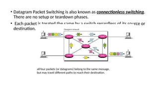
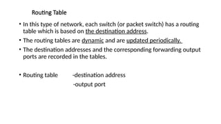
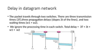
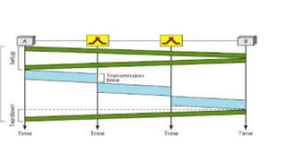
• The network layer in the TCP/IP protocol suite is responsible for the host-tohost
delivery of datagrams.
• It provides services to the transport layer and receives services from the datalink
layer.
• The network layer translates the logical addresses into physical addresses
• It determines the route from the source to the destination and also manages the
traffic problems such as switching, routing and controls the congestion of data
packets.
• The main role of the network layer is to move the packets from sending host to
the receiving host.
• PACKETIZING
• This means encapsulating the payload (data received from upper layer) in a network-layer
packet at the source and decapsulating the payload from the network-layer packet at the
destination.
• ROUTING AND FORWARDING
• Routing
• The network layer is responsible for routing the packet from its source to the
destination and for finding the best one among these possible routes. The
network layer needs to have some specific strategies for defining the best
route.
• Routing is the concept of applying strategies and running routing protocols to
create the decision-making tables for each router. These tables are called as
routing tables.
• Forwarding
• It can be defined as the action applied by each router when a packet
arrives at one of its interfaces.
• The decision-making table, a router normally uses for applying this
action is called the forwarding table.
• When a router receives a packet from one of its attached networks, it
needs to forward the packet to another attached network.
• FLOW CONTROL
• Flow control regulates the amount of data a source can send without
overwhelming the receiver.
• The network layer in the Internet, however, does not directly provide
any flow control. The datagrams are sent by the sender when they
are ready, without any attention to the readiness of the receiver.
• Flow control is provided for most of the upper-layer protocols that
use the services of the network layer, so another level of flow control
makes the network layer more complicated and the whole system less
efficient.
• CONGESTION CONTROL
• Another issue in a network-layer protocol is congestion control. 
Congestion in the network layer is a situation in which too many
datagrams are present in an area of the Internet.
• Congestion may occur if the number of datagrams sent by source
computers is beyond the capacity of the network or routers.
• In this situation, some routers may drop some of the datagrams.
• SECURITY
• Another issue related to communication at the network layer is
security.
• To provide security for a connectionless network layer, we need to
have another virtual level that changes the connectionless service to a
connectionoriented service.
• This virtual layer is called as called IPSec (IP Security).
• SECURITY
• To provide security for a connectionless network layer, we need to
have another virtual level that changes the connectionless service to a
connection oriented service.
• This virtual layer is called as called IPSec (IP Security)
PACKET SWITCHING
• The packet switching is a switching technique in which the message is
sent in one go, but it is divided into smaller pieces, and they are sent
individually.
• The message splits into smaller pieces known as packets and packets
are given a unique number to identify their order at the receiving end.
• Every packet contains some information in its headers such as source
address, destination address and sequence number.
• Packets will travel across the network, taking the shortest path as
possible.
• All the packets are reassembled at the receiving end in correct order.
If any packet is missing or corrupted, then the message will be sent to
resend the message.
• If the correct order of the packets is reached, then the
acknowledgment message will be sent.
ADVANTAGES
• Cost-effective: In packet switching technique, switching devices do
not require massive secondary storage to store the packets, so cost is
minimized to some extent.
• Reliable: If any node is busy, then the packets can be rerouted. This
ensures that the Packet Switching technique provides reliable
communication.
• Efficient: Packet Switching is an efficient technique. It does not
require any established path prior to the transmission, and many
users can use the same communication channel simultaneously,
hence makes use of available bandwidth very efficiently.
DISADVANTAGES
• Packet Switching technique cannot be implemented in the
applications that require low delay and high-quality services.
• The protocols used in a packet switching technique are very complex
and requires high implementation cost.
• If the network is overloaded or corrupted, then it requires
retransmission of lost packets. It can also lead to the loss of critical
information if errors are nor recovered.
APPROACHES OF PACKET SWITCHING
o Datagram Packet switching
o Virtual Circuit Switching
• Datagram Packet switching (connectionless switching)
• It is a packet switching technology in which packet is known as a
datagram, is considered as an independent entity.
• Each packet contains the information about the destination and
switch uses this information to forward the packet to the correct
destination.
• The packets are reassembled at the receiving end in correct order.
• In Datagram Packet Switching technique, the path is not fixed.
Intermediate nodes take the routing decisions to forward the packets.
• Datagram Packet Switching is also known as connectionless switching.
There are no setup or teardown phases.
• Each packet is treated the same by a switch regardless of its source or
destination.
all four packets (or datagrams) belong to the same message,
but may travel different paths to reach their destination.
Routing Table
• In this type of network, each switch (or packet switch) has a routing
table which is based on the destination address.
• The routing tables are dynamic and are updated periodically.
• The destination addresses and the corresponding forwarding output
ports are recorded in the tables.
• Routing table -destination address
-output port
Delay in datagram network
• The packet travels through two switches. There are three transmission
times (3T),three propagation delays (slopes 3t of the lines), and two
waiting times (w1 + w2).
• We ignore the processing time in each switch. Total delay = 3T + 3t +
w1 + w2
• Virtual Circuit Switching
• Virtual Circuit Switching is also known as connection-oriented
switching.
• In the case of Virtual circuit switching, a virtual connection is
established before the messages are sent.
• Call request and call accept packets are used to establish the
connection between sender and receiver.
• In this case, the path is fixed for the duration of a logical connection
• Virtual Circuit Identifier (VCI)
• A virtual circuit identifier (VCI) that uniquely identifies the connection
at this switch.
• A VCI, unlike a global address, is a small number that has only switch
scope; it is used by a frame between two switches.
• When a frame arrives at a switch, it has a VCI; when it leaves, it has a
different VCI.
• Virtual Circuit Table
• Every Virtual Circuit (VC) maintains a table called Virtual Circuit table.
One entry in the VC table on a single switch contains the following :
• An incoming interface on which packets for this VC arrive at the switch
• An outgoing interface in which packets for this VC leave the switch
• A outgoing VCI that will be used for outgoing packets
• Types of Virtual Circuits
• There are two broad classes of Virtual Circuits.
• They are 1. PVC – Permanent Virtual Circuit
• Network Administrator will configure the state
• The virtual circuit is permanent (PVC)
• 2. SVC – Switched Virtual Circuit
• A host can send messages into the network to cause the state to be
established. This is referred as signaling.
• A host may set up and delete such a VC dynamically without the
involvement of a network administrator.
Delay in Virtual-Circuit Networks
The packet is traveling through two switches (routers)
• There are three transmission times (3T ),
• three propagation times (3t)
• data transfer depicted by the sloping lines,
• setup delay (which includes transmission and propagation in two directions),
• teardown delay (which includes transmission and propagation in one direction).
INTERNET PROTOCOL
• The Internet Protocol is the key tool used today to build scalable,
heterogeneous internetworks.
• IP runs on all the nodes (both hosts and routers) in a collection of
networks.
• IP defines the infrastructure that allows these nodes and networks to
function as a single logical internetwork.
• IP SERVICE MODEL
• Service Model defines the host-to-host services that we want to provide
• The main concern in defining a service model for an internetwork is that
we can provide a host-to-host service only if this service can somehow be
provided over each of the underlying physical networks.
• The Internet Protocol is the key tool used today to build scalable,
heterogeneous internetworks.
• The IP service model can be thought of as having two parts:
• A GLOBAL ADDRESSING SCHEME - which provides a way to identify
all hosts in the internetwork
• A DATAGRAM DELIVERY MODEL – A connectionless model of data
delivery.
IP PACKET FORMAT / IP DATAGRAM FORMAT
• A key part of the IP service model is the type of packets that can be
carried.
• The IP datagram consists of a header followed by a number of bytes
of data.
• FIELD DESCRIPTION
• Version Specifies the version of IP.
• Two versions exists – IPv4 and IPv6.
• HLen Specifies the length of the header
• TOS (Type of Service) An indication of the parameters of the quality of
service desired such as Precedence, Delay, Throughput and Reliability.
• Length Length of the entire datagram,including the header.
• The maximum size of an IP datagram is 65,535(210 )bytes
• Ident (Identification) Uniquely identifies the packet sequence number.
Used for fragmentation and re-assembly.
• Flags Used to control whether routers are allowed to fragment a packet. If a packet is
fragmented , this flag value is 1.If not, flag value is 0.
• Offset (Fragmentation offset) Indicates where in the datagram, this fragment belongs.
The fragment offset is measured in units of 8 octets (64 bits). The first fragment has
offset zero.
• TTL (Time to Live) Indicates the maximum time the datagram is allowed to remain in
the network. If this field contains the value zero, then the datagram must be destroyed.
• Protocol Indicates the next level protocol used in the data portion of the datagram
• Checksum Used to detect the processing errors introduced into the packet
• Source Address The IP address of the original sender of the packet. Destination
Address The IP address of the final destination of the packet. Options This is optional
field. These options may contain values for options such as Security, Record Route, Time
Stamp, etc
• Pad Used to ensure that the internet header ends on a 32 bit boundary. The padding is
zero.
IP DATAGRAM- FRAGMENTATION AND REASSEMBLY
• Every network type has a maximum transmission unit (MTU), which is the largest
IP datagram that it can carry in a frame.
• Fragmentation of a datagram will only be necessary if the path to the destination
includes a network with a smaller MTU.
• When a host sends an IP datagram,it can choose any size that it wants.
• Fragmentation typically occurs in a router when it receives a datagram that it
wants to forward over a network that has an MTU that is smaller than the
received datagram.
• Each fragment is itself a self-contained IP datagram that is transmitted over a
sequence of physical networks, independent of the other fragments.
• Each IP datagram is re-encapsulated for each physical network over which it
travels.
The original packet starts at the client; the fragments are reassembled at the server.
The value of the identification field is the same in all fragments, as is the value of the flags field with the
more bit set for all fragments except the last.
Also, the value of the offset field for each fragment is shown.
Although the fragments arrived out of order at the destination, they can be correctly reassembled.
• 1) The first fragment has an offset field value of zero.
• 2) Divide the length of the first fragment by 8.
• The second fragment has an offset value equal to that result.
• 3) Divide the total length of the first and second fragment by 8. The
third fragment has an offset value equal to that result.
• 4) Continue the process. The last fragment has its M bit set to 0. 5)
Continue the process.
• The last fragment has a more bit value of 0.
• ((((divide by 0))))
• Reassembly:
• Reassembly is done at the receiving host and not at each router.
• To enable these fragments to be reassembled at the receiving host, they all carry
the same identifier in the Ident field.
• This identifier is chosen by the sending host and is intended to be unique among
all the datagrams that might arrive at the destination from this source over some
reasonable time period.
• Since all fragments of the original datagram contain this identifier, the
reassembling host will be able to recognize those fragments that go together.
• For example, if a single fragment is lost, the receiver will still attempt to
reassemble the datagram, and it will eventually give up and have to garbagecollect
the resources that were used to perform the failed reassembly.
• Hosts are now strongly encouraged to perform “path MTU discovery,” a process
by which fragmentation is avoided by sending packets that are small enough to
traverse the link with the smallest MTU in the path from sender to receiver.
• IP SECURITY There are three security issues that are particularly
applicable to the IP protocol:
• (1)Packet Sniffing
• (2) Packet Modification and
• (3) IP Spoofing.
• (1)Packet Sniffing
An intruder may intercept an IP packet and make a copy of it.
Packet sniffing is a passive attack, in which the attacker does not change
the contents of the packet.(may or maynot know)
Encrypting the packet .still they can copy but cant detect the data.
• Packet Modification
• The second type of attack is to modify the packet.
• The attacker intercepts the packet,changes its contents, and sends
the new packet to the receiver.
• The receiver believes that the packet is coming from the original
sender.
• This type of attack can be detected using a data integrity mechanism.
• The receiver, before opening and using the contents of the message,
can use this mechanism to make sure that the packet has not been
changed during the transmission
• IP Spoofing
• An attacker can masquerade as somebody else and create an IP packet that
carries the source address of another computer.
• An attacker can send an IP packet to a bank pretending that it is coming from
one of the customers.
• This type of attack can be prevented using an origin authentication
mechanism .((((FAKE ID)))
• IP Sec (SOLUTION)
• The IP packets today can be protected from the previously mentioned attacks
using a protocol called IPSec (IP Security).
• This protocol is used in conjunction with the IP protocol.
• IPSec protocol creates a connection-oriented service between two entities
in which they can exchange IP packets without worrying about the three
attacks such as Packet Sniffing, Packet Modification and IP Spoofing.
• 1.Defining Algorithms and Keys : The two entities that want to create a
secure channel between themselves can agree on some available algorithms
and keys to be used for security purposes.
• 2) Packet Encryption : The packets exchanged between two parties can be
encrypted for privacy using one of the encryption algorithms and a shared
key agreed upon in the first step. This makes the packet sniffing attack
useless.
• 3) Data Integrity : Data integrity guarantees that the packet is not modified
during the transmission. If the received packet does not pass the data
integrity test, it is discarded.This prevents the second attack, packet
modification.
• 4)Origin Authentication : IPSec can authenticate the origin of the packet to
be sure that the packet is not created by an imposter. This can prevent IP
spoofing attacks.

unit 3 computer networks-switching,packet switching,internet protocol.

  • 1.
  • 2.
    NETWORK LAYER • Thenetwork layer in the TCP/IP protocol suite is responsible for the host-tohost delivery of datagrams. • It provides services to the transport layer and receives services from the datalink layer. • The network layer translates the logical addresses into physical addresses • It determines the route from the source to the destination and also manages the traffic problems such as switching, routing and controls the congestion of data packets. • The main role of the network layer is to move the packets from sending host to the receiving host.
  • 3.
    • PACKETIZING • Thismeans encapsulating the payload (data received from upper layer) in a network-layer packet at the source and decapsulating the payload from the network-layer packet at the destination. • ROUTING AND FORWARDING • Routing • The network layer is responsible for routing the packet from its source to the destination and for finding the best one among these possible routes. The network layer needs to have some specific strategies for defining the best route. • Routing is the concept of applying strategies and running routing protocols to create the decision-making tables for each router. These tables are called as routing tables.
  • 4.
    • Forwarding • Itcan be defined as the action applied by each router when a packet arrives at one of its interfaces. • The decision-making table, a router normally uses for applying this action is called the forwarding table. • When a router receives a packet from one of its attached networks, it needs to forward the packet to another attached network.
  • 5.
    • FLOW CONTROL •Flow control regulates the amount of data a source can send without overwhelming the receiver. • The network layer in the Internet, however, does not directly provide any flow control. The datagrams are sent by the sender when they are ready, without any attention to the readiness of the receiver. • Flow control is provided for most of the upper-layer protocols that use the services of the network layer, so another level of flow control makes the network layer more complicated and the whole system less efficient.
  • 6.
    • CONGESTION CONTROL •Another issue in a network-layer protocol is congestion control.  Congestion in the network layer is a situation in which too many datagrams are present in an area of the Internet. • Congestion may occur if the number of datagrams sent by source computers is beyond the capacity of the network or routers. • In this situation, some routers may drop some of the datagrams.
  • 7.
    • SECURITY • Anotherissue related to communication at the network layer is security. • To provide security for a connectionless network layer, we need to have another virtual level that changes the connectionless service to a connectionoriented service. • This virtual layer is called as called IPSec (IP Security).
  • 8.
    • SECURITY • Toprovide security for a connectionless network layer, we need to have another virtual level that changes the connectionless service to a connection oriented service. • This virtual layer is called as called IPSec (IP Security)
  • 9.
    PACKET SWITCHING • Thepacket switching is a switching technique in which the message is sent in one go, but it is divided into smaller pieces, and they are sent individually. • The message splits into smaller pieces known as packets and packets are given a unique number to identify their order at the receiving end. • Every packet contains some information in its headers such as source address, destination address and sequence number. • Packets will travel across the network, taking the shortest path as possible.
  • 10.
    • All thepackets are reassembled at the receiving end in correct order. If any packet is missing or corrupted, then the message will be sent to resend the message. • If the correct order of the packets is reached, then the acknowledgment message will be sent.
  • 11.
    ADVANTAGES • Cost-effective: Inpacket switching technique, switching devices do not require massive secondary storage to store the packets, so cost is minimized to some extent. • Reliable: If any node is busy, then the packets can be rerouted. This ensures that the Packet Switching technique provides reliable communication. • Efficient: Packet Switching is an efficient technique. It does not require any established path prior to the transmission, and many users can use the same communication channel simultaneously, hence makes use of available bandwidth very efficiently.
  • 12.
    DISADVANTAGES • Packet Switchingtechnique cannot be implemented in the applications that require low delay and high-quality services. • The protocols used in a packet switching technique are very complex and requires high implementation cost. • If the network is overloaded or corrupted, then it requires retransmission of lost packets. It can also lead to the loss of critical information if errors are nor recovered.
  • 13.
    APPROACHES OF PACKETSWITCHING o Datagram Packet switching o Virtual Circuit Switching • Datagram Packet switching (connectionless switching) • It is a packet switching technology in which packet is known as a datagram, is considered as an independent entity. • Each packet contains the information about the destination and switch uses this information to forward the packet to the correct destination. • The packets are reassembled at the receiving end in correct order. • In Datagram Packet Switching technique, the path is not fixed. Intermediate nodes take the routing decisions to forward the packets.
  • 14.
    • Datagram PacketSwitching is also known as connectionless switching. There are no setup or teardown phases. • Each packet is treated the same by a switch regardless of its source or destination. all four packets (or datagrams) belong to the same message, but may travel different paths to reach their destination.
  • 15.
    Routing Table • Inthis type of network, each switch (or packet switch) has a routing table which is based on the destination address. • The routing tables are dynamic and are updated periodically. • The destination addresses and the corresponding forwarding output ports are recorded in the tables. • Routing table -destination address -output port
  • 16.
    Delay in datagramnetwork • The packet travels through two switches. There are three transmission times (3T),three propagation delays (slopes 3t of the lines), and two waiting times (w1 + w2). • We ignore the processing time in each switch. Total delay = 3T + 3t + w1 + w2
  • 17.
    • Virtual CircuitSwitching • Virtual Circuit Switching is also known as connection-oriented switching. • In the case of Virtual circuit switching, a virtual connection is established before the messages are sent. • Call request and call accept packets are used to establish the connection between sender and receiver. • In this case, the path is fixed for the duration of a logical connection
  • 18.
    • Virtual CircuitIdentifier (VCI) • A virtual circuit identifier (VCI) that uniquely identifies the connection at this switch. • A VCI, unlike a global address, is a small number that has only switch scope; it is used by a frame between two switches. • When a frame arrives at a switch, it has a VCI; when it leaves, it has a different VCI.
  • 19.
    • Virtual CircuitTable • Every Virtual Circuit (VC) maintains a table called Virtual Circuit table. One entry in the VC table on a single switch contains the following : • An incoming interface on which packets for this VC arrive at the switch • An outgoing interface in which packets for this VC leave the switch • A outgoing VCI that will be used for outgoing packets
  • 20.
    • Types ofVirtual Circuits • There are two broad classes of Virtual Circuits. • They are 1. PVC – Permanent Virtual Circuit • Network Administrator will configure the state • The virtual circuit is permanent (PVC) • 2. SVC – Switched Virtual Circuit • A host can send messages into the network to cause the state to be established. This is referred as signaling. • A host may set up and delete such a VC dynamically without the involvement of a network administrator.
  • 21.
    Delay in Virtual-CircuitNetworks The packet is traveling through two switches (routers) • There are three transmission times (3T ), • three propagation times (3t) • data transfer depicted by the sloping lines, • setup delay (which includes transmission and propagation in two directions), • teardown delay (which includes transmission and propagation in one direction).
  • 23.
    INTERNET PROTOCOL • TheInternet Protocol is the key tool used today to build scalable, heterogeneous internetworks. • IP runs on all the nodes (both hosts and routers) in a collection of networks. • IP defines the infrastructure that allows these nodes and networks to function as a single logical internetwork. • IP SERVICE MODEL • Service Model defines the host-to-host services that we want to provide • The main concern in defining a service model for an internetwork is that we can provide a host-to-host service only if this service can somehow be provided over each of the underlying physical networks.
  • 24.
    • The InternetProtocol is the key tool used today to build scalable, heterogeneous internetworks. • The IP service model can be thought of as having two parts: • A GLOBAL ADDRESSING SCHEME - which provides a way to identify all hosts in the internetwork • A DATAGRAM DELIVERY MODEL – A connectionless model of data delivery.
  • 25.
    IP PACKET FORMAT/ IP DATAGRAM FORMAT • A key part of the IP service model is the type of packets that can be carried. • The IP datagram consists of a header followed by a number of bytes of data.
  • 26.
    • FIELD DESCRIPTION •Version Specifies the version of IP. • Two versions exists – IPv4 and IPv6. • HLen Specifies the length of the header • TOS (Type of Service) An indication of the parameters of the quality of service desired such as Precedence, Delay, Throughput and Reliability. • Length Length of the entire datagram,including the header. • The maximum size of an IP datagram is 65,535(210 )bytes • Ident (Identification) Uniquely identifies the packet sequence number. Used for fragmentation and re-assembly.
  • 27.
    • Flags Usedto control whether routers are allowed to fragment a packet. If a packet is fragmented , this flag value is 1.If not, flag value is 0. • Offset (Fragmentation offset) Indicates where in the datagram, this fragment belongs. The fragment offset is measured in units of 8 octets (64 bits). The first fragment has offset zero. • TTL (Time to Live) Indicates the maximum time the datagram is allowed to remain in the network. If this field contains the value zero, then the datagram must be destroyed. • Protocol Indicates the next level protocol used in the data portion of the datagram • Checksum Used to detect the processing errors introduced into the packet • Source Address The IP address of the original sender of the packet. Destination Address The IP address of the final destination of the packet. Options This is optional field. These options may contain values for options such as Security, Record Route, Time Stamp, etc • Pad Used to ensure that the internet header ends on a 32 bit boundary. The padding is zero.
  • 28.
    IP DATAGRAM- FRAGMENTATIONAND REASSEMBLY • Every network type has a maximum transmission unit (MTU), which is the largest IP datagram that it can carry in a frame. • Fragmentation of a datagram will only be necessary if the path to the destination includes a network with a smaller MTU. • When a host sends an IP datagram,it can choose any size that it wants. • Fragmentation typically occurs in a router when it receives a datagram that it wants to forward over a network that has an MTU that is smaller than the received datagram. • Each fragment is itself a self-contained IP datagram that is transmitted over a sequence of physical networks, independent of the other fragments. • Each IP datagram is re-encapsulated for each physical network over which it travels.
  • 29.
    The original packetstarts at the client; the fragments are reassembled at the server. The value of the identification field is the same in all fragments, as is the value of the flags field with the more bit set for all fragments except the last. Also, the value of the offset field for each fragment is shown. Although the fragments arrived out of order at the destination, they can be correctly reassembled.
  • 30.
    • 1) Thefirst fragment has an offset field value of zero. • 2) Divide the length of the first fragment by 8. • The second fragment has an offset value equal to that result. • 3) Divide the total length of the first and second fragment by 8. The third fragment has an offset value equal to that result. • 4) Continue the process. The last fragment has its M bit set to 0. 5) Continue the process. • The last fragment has a more bit value of 0. • ((((divide by 0))))
  • 31.
    • Reassembly: • Reassemblyis done at the receiving host and not at each router. • To enable these fragments to be reassembled at the receiving host, they all carry the same identifier in the Ident field. • This identifier is chosen by the sending host and is intended to be unique among all the datagrams that might arrive at the destination from this source over some reasonable time period. • Since all fragments of the original datagram contain this identifier, the reassembling host will be able to recognize those fragments that go together. • For example, if a single fragment is lost, the receiver will still attempt to reassemble the datagram, and it will eventually give up and have to garbagecollect the resources that were used to perform the failed reassembly. • Hosts are now strongly encouraged to perform “path MTU discovery,” a process by which fragmentation is avoided by sending packets that are small enough to traverse the link with the smallest MTU in the path from sender to receiver.
  • 32.
    • IP SECURITYThere are three security issues that are particularly applicable to the IP protocol: • (1)Packet Sniffing • (2) Packet Modification and • (3) IP Spoofing. • (1)Packet Sniffing An intruder may intercept an IP packet and make a copy of it. Packet sniffing is a passive attack, in which the attacker does not change the contents of the packet.(may or maynot know) Encrypting the packet .still they can copy but cant detect the data.
  • 33.
    • Packet Modification •The second type of attack is to modify the packet. • The attacker intercepts the packet,changes its contents, and sends the new packet to the receiver. • The receiver believes that the packet is coming from the original sender. • This type of attack can be detected using a data integrity mechanism. • The receiver, before opening and using the contents of the message, can use this mechanism to make sure that the packet has not been changed during the transmission
  • 34.
    • IP Spoofing •An attacker can masquerade as somebody else and create an IP packet that carries the source address of another computer. • An attacker can send an IP packet to a bank pretending that it is coming from one of the customers. • This type of attack can be prevented using an origin authentication mechanism .((((FAKE ID))) • IP Sec (SOLUTION) • The IP packets today can be protected from the previously mentioned attacks using a protocol called IPSec (IP Security). • This protocol is used in conjunction with the IP protocol. • IPSec protocol creates a connection-oriented service between two entities in which they can exchange IP packets without worrying about the three attacks such as Packet Sniffing, Packet Modification and IP Spoofing.
  • 35.
    • 1.Defining Algorithmsand Keys : The two entities that want to create a secure channel between themselves can agree on some available algorithms and keys to be used for security purposes. • 2) Packet Encryption : The packets exchanged between two parties can be encrypted for privacy using one of the encryption algorithms and a shared key agreed upon in the first step. This makes the packet sniffing attack useless. • 3) Data Integrity : Data integrity guarantees that the packet is not modified during the transmission. If the received packet does not pass the data integrity test, it is discarded.This prevents the second attack, packet modification. • 4)Origin Authentication : IPSec can authenticate the origin of the packet to be sure that the packet is not created by an imposter. This can prevent IP spoofing attacks.