SlideShare a Scribd company logo
1 of 51
Download to read offline
Fluid Mechanics – Cengel and Cimbala + NPTEL
(Condensed)
A solid can resist an applied shear stress by deforming, whereas a fluid deforms continuously under
the influence of a shear stress, no matter how small. In solids, stress is proportional to strain, but
in fluids, stress is proportional to strain rate. When a constant shear force is applied, a solid
eventually stops deforming at some fixed strain angle, whereas a fluid never stops deforming and
approaches a constant rate of strain.
Particularly at low densities, the intermolecular forces are very small, and collisions are the only
mode of interaction between the molecules. Molecules in the gas phase are at a considerably
higher energy level than they are in the liquid or solid phase. Therefore, the gas must release a
large amount of its energy before it can condense or freeze.
NO SLIP CONDITION
Water in a river cannot flow through large rocks and must go around them. That is, the water
velocity normal to the rock surface must be zero, and water approaching the surface normally
comes to a complete stop at the surface. What is not as obvious is that water approaching the
rock at any angle also comes to a complete stop at the rock surface, and thus the tangential
velocity of water at the surface is also zero. That is, a fluid in direct contact with a solid “sticks” to
the surface, and there is no slip. This is known as the no-slip condition. The fluid property
responsible for the no-slip condition and the development of the boundary layer is viscosity.
The no-slip condition is responsible for the development of the velocity profile. The flow
region adjacent to the wall in which the viscous effects (and thus the velocity gradients) are
significant is called the boundary layer. Another consequence of the no-slip condition is the surface
drag, or skin friction drag, which is the force a fluid exerts on a surface in the flow direction.
When a fluid is forced to flow over a curved surface, such as the back side of a cylinder, the
boundary layer may no longer remain attached to the surface and separates from the surface—a
process called flow separation.
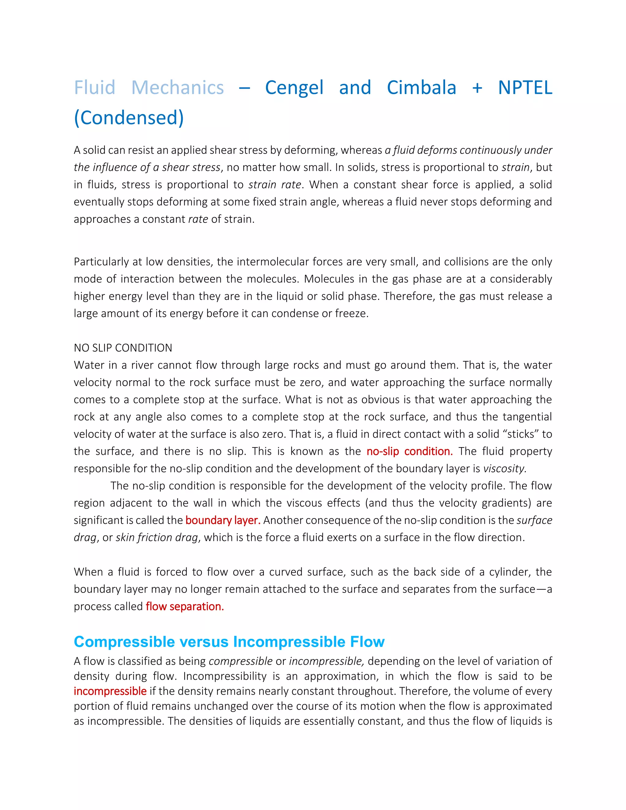
Compressible versus Incompressible Flow
A flow is classified as being compressible or incompressible, depending on the level of variation of
density during flow. Incompressibility is an approximation, in which the flow is said to be
incompressible if the density remains nearly constant throughout. Therefore, the volume of every
portion of fluid remains unchanged over the course of its motion when the flow is approximated
as incompressible. The densities of liquids are essentially constant, and thus the flow of liquids is
typically incompressible. Therefore, liquids are usually referred to as incompressible substances. A
pressure of 210 atm, for example, causes the density of liquid water at 1 atm to change by just 1
percent. Gases, on the other hand, are highly compressible. A pressure change of just 0.01 atm,
for example, causes a change of 1 percent in the density of atmospheric air.
When analyzing rockets, spacecraft, and other systems that involve high-speed gas flows,
the flow speed is often expressed in terms of the dimensionless Mach number defined as
Where c is the speed of sound whose value is 346 m/s in air at room temperature at sea level. A
flow is called Sonic when Ma = 1, subsonic when Ma<1, supersonic when Ma>1, and hypersonic
when Ma>>1. Liquid flows are incompressible to a high level of accuracy, but the level of variation
of density in gas flows and the consequent level of approximation made when modeling gas flows
as incompressible depends on the Mach number. Gas flows can often be approximated as
incompressible if the density changes are under about 5 percent, which is usually the case when
Ma<0.3. Therefore, the compressibility effects of air at room temperature can be neglected at
speeds under about 100 m/s.
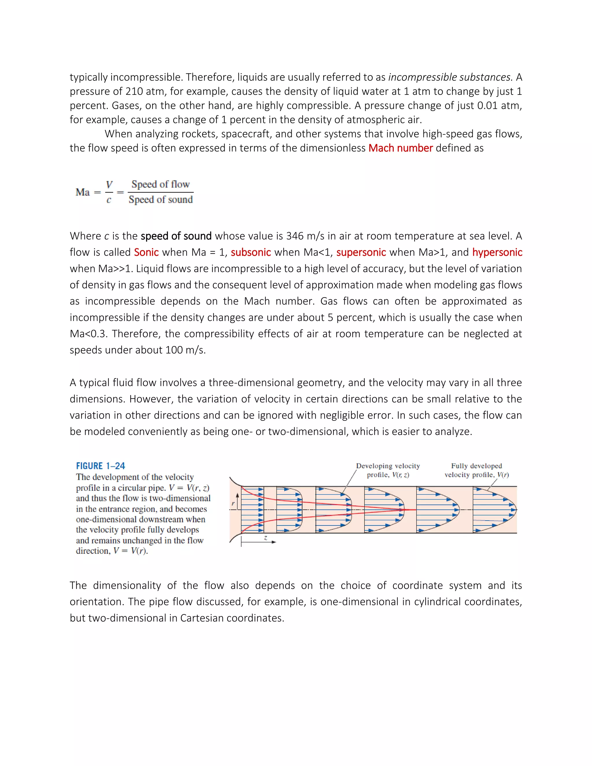
A typical fluid flow involves a three-dimensional geometry, and the velocity may vary in all three
dimensions. However, the variation of velocity in certain directions can be small relative to the
variation in other directions and can be ignored with negligible error. In such cases, the flow can
be modeled conveniently as being one- or two-dimensional, which is easier to analyze.
The dimensionality of the flow also depends on the choice of coordinate system and its
orientation. The pipe flow discussed, for example, is one-dimensional in cylindrical coordinates,
but two-dimensional in Cartesian coordinates.
CONTINUUM
A fluid is composed of molecules which may be widely spaced apart, especially in the gas phase.
Yet it is convenient to disregard the atomic nature of the fluid and view it as continuous,
homogeneous matter with no holes, that is, a continuum. The continuum idealization allows us to
treat properties as point functions and to assume that the properties vary continually in space
with no jump discontinuities. This idealization is valid as long as the size of the system we deal with
is large relative to the space between the molecules.
VAPOR PRESSURE AND CAVITATION
At a given pressure, the temperature at which a pure substance changes phase is called the
saturation temperature Tsat. Likewise, at a given temperature, the pressure at which a pure
substance changes phase is called the saturation pressure Psat. The vapor pressure Pv of a pure
substance is defined as the pressure exerted by its vapor in phase equilibrium with its liquid at a
given temperature. Pv is a property of the pure substance, and turns out to be identical to the
saturation pressure Psat of the liquid (Pv = Psat).
The partial pressure of a vapor must be less than or equal to the vapor pressure if there is no liquid
present. However, when both vapor and liquid are present and the system is in phase equilibrium,
the partial pressure of the vapor must equal the vapor pressure, and the system is said to be
saturated.
The vapor pressure of water at 20°C is 2.34 kPa. Therefore, a bucket of water at 20°C left in a room
with dry air at 1 atm will continue evaporating until one of two things happens: the water
evaporates away (there is not enough water to establish phase equilibrium in the room), or the
evaporation stops when the partial pressure of the water vapor in the room rises to 2.34 kPa at
which point phase equilibrium is established.
For phase-change processes between the liquid and vapor phases of a pure substance, the
saturation pressure and the vapor pressure are equivalent since the vapor is pure. The pressure
value would be the same whether it is measured in the vapor or liquid phase (provided that it is
measured at a location close to the liquid–vapor interface to avoid any hydrostatic effects). Vapor
pressure increases with temperature. Thus, a substance at higher pressure boils at higher
temperature. For example, water boils at 134°C in a pressure cooker operating at 3 atm absolute
pressure, but it boils at 93°C in an ordinary pan at a 2000-m elevation, where the atmospheric
pressure is 0.8 atm.
There is a possibility of the liquid pressure in liquid-flow systems dropping below the vapor
pressure at some locations, and the resulting unplanned vaporization. For example, water at 10°C
may vaporize and form bubbles at locations (such as the tip regions of impellers or suction sides
of pumps) where the pressure drops below 1.23 kPa. The vapor bubbles (called cavitation bubbles
since they form “cavities” in the liquid) collapse as they are swept away from the low-pressure
regions, generating highly destructive, extremely high-pressure waves
A large value of κ indicates that a large change in pressure is needed to cause a small fractional
change in volume, and thus a fluid with a large k is essentially incompressible. This is typical for
liquids, and explains why liquids are usually considered to be incompressible.
Therefore, the coefficient of compressibility of an ideal gas is equal to its absolute pressure.
The viscosity of a fluid depends on both temperature and pressure, although the dependence on
pressure is rather weak. For liquids, both the dynamic and kinematic viscosities are practically
independent of pressure, and any small variation with pressure is usually disregarded, except at
extremely high pressures. For gases, this is also the case for dynamic viscosity (at low to moderate
pressures), but not for kinematic viscosity since the density of a gas is proportional to its pressure.
The viscosity of a fluid is a measure of its “resistance to deformation.” Viscosity is due to the
internal frictional force that develops between different layers of fluids as they are forced to move
relative to each other.
The viscosity of a fluid is directly related to the pumping power needed to transport a fluid in a
pipe or to move a body (such as a car in air or a submarine in the sea) through a fluid. Viscosity is
caused by the cohesive forces between the molecules in liquids and by the molecular collisions in
gases, and it varies greatly with temperature. The viscosity of liquids decreases with temperature,
whereas the viscosity of gases increases with temperature. This is because in a liquid the molecules
possess more energy at higher temperatures, and they can oppose the large cohesive
intermolecular forces more strongly. As a result, the energized liquid molecules can move more
freely. In a gas, on the other hand, the intermolecular forces are negligible, and the gas molecules
at high temperatures move randomly at higher velocities. This results in more molecular collisions
per unit volume per unit time and therefore in greater resistance to flow.
SURFACE TENSION AND CAPILLARY EFFECT
Therefore, there is a net attractive force acting on the
molecule at the surface of the liquid, which tends to pull the molecules on the surface toward the
interior of the liquid. This force is balanced by the repulsive forces from the molecules below the
surface that are trying to be compressed. The result is that the liquid minimizes its surface area.
This is the reason for the tendency of liquid droplets to attain a spherical shape, which has the
minimum surface area for a given volume.
A curved interface indicates a pressure difference (or “pressure jump”) across the interface with
pressure being higher on the concave side. Consider, for example, a droplet of liquid in air, an air
(or other gas) bubble in water, or a soap bubble in air. The excess pressure ΔP above atmospheric
pressure can be determined by considering a free-body diagram of half the droplet or bubble (Fig.
2–34). Noting that surface tension acts along the circumference
and the pressure acts on the area, horizontal force balances for the droplet or air bubble and the
soap bubble give
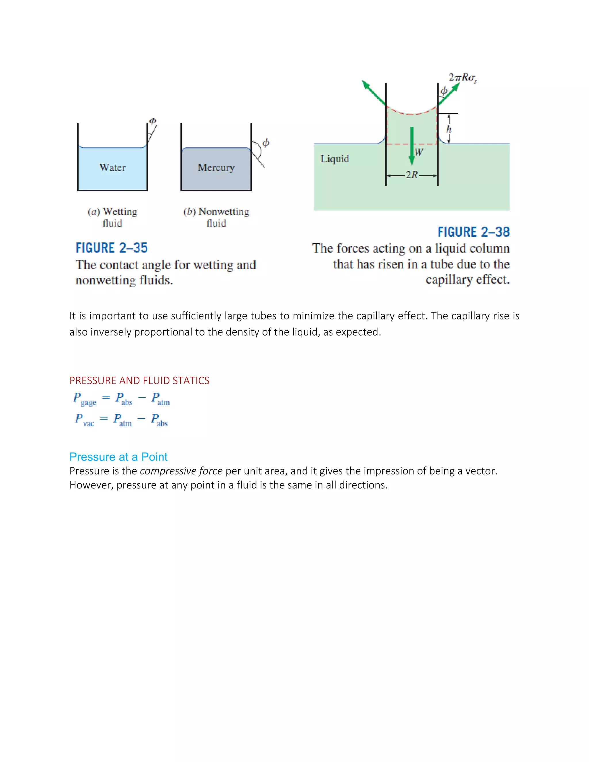
Capillary Effect
Another consequence of surface tension is the capillary effect, which is the rise or fall of a liquid in
a small-diameter tube inserted into the liquid. Such narrow tubes or confined flow channels are
called capillaries.
It is important to use sufficiently large tubes to minimize the capillary effect. The capillary rise is
also inversely proportional to the density of the liquid, as expected.
PRESSURE AND FLUID STATICS
Pressure at a Point
Pressure is the compressive force per unit area, and it gives the impression of being a vector.
However, pressure at any point in a fluid is the same in all directions.
Pressure in a fluid at rest is independent of the
shape or cross section of the container. It changes with the vertical distance, but remains
constant in other directions. Therefore, the pressure is the same at all points on a horizontal
plane in a given fluid.
A consequence of the pressure in a fluid remaining constant in the horizontal direction is
that the pressure applied to a confined fluid increases the pressure throughout by the same
amount. This is called Pascal’s law.
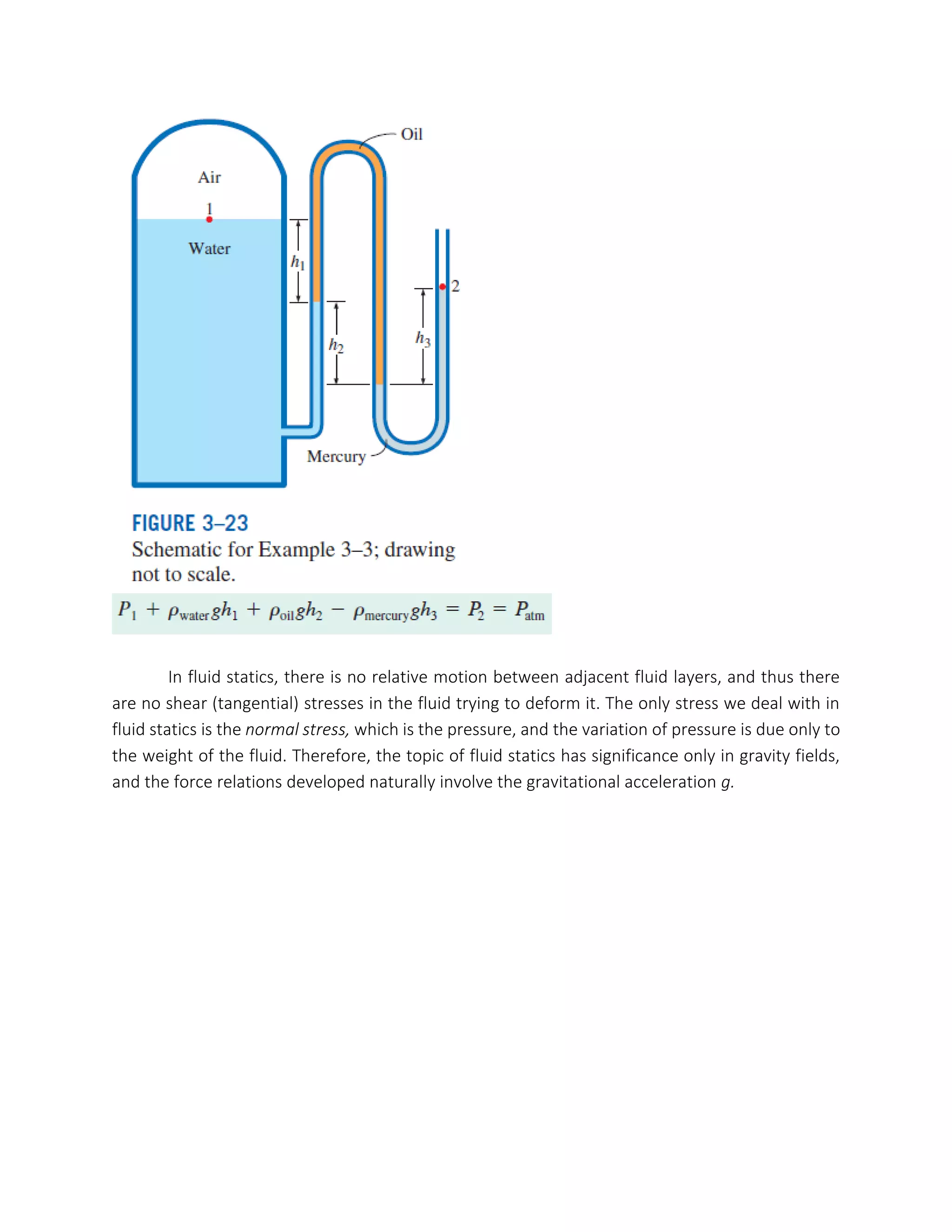
In fluid statics, there is no relative motion between adjacent fluid layers, and thus there
are no shear (tangential) stresses in the fluid trying to deform it. The only stress we deal with in
fluid statics is the normal stress, which is the pressure, and the variation of pressure is due only to
the weight of the fluid. Therefore, the topic of fluid statics has significance only in gravity fields,
and the force relations developed naturally involve the gravitational acceleration g.
if tube is inclined, difference in elevation measures piezometric head difference rather than just static
pressure head difference between two points.
to measure very low pressure difference, difference between working fluid and manometric fluid should
be low as possible but at the same time we have to see proper meniscus formation which not possible
fluids having nearly same density.
above is a solution to show large deflection even for low pressure change.
Geometrical magnification done by just providing inclination. Experimenter will measure the
displacement of manometric fluid along the length of the tube.
We do not make container transparent.
But we cannot make theta so small that free surface will cause error in the measurement.
The magnitude of the resultant force acting on a
plane surface of a completely submerged plate in a homogeneous (constant density) fluid is equal
to the product of the pressure PC at the centroid of the surface and the area A of the surface.
Same force whether placed inclined or horizontal; point is vertical depth of horizontally placed plate
should be same as the centre of area of inclined plate. When we discuss the hydrostatic forces of plates
submerged, we assume other side is kind of atmospheric, because net force is zero on the plate. How
could we say that the forces are acting.
forces are parallel to each other in the case of flat plates, but in curved surfaces forces will act normal to
the surface which are not parallel to each other. Therefore simple scalar summation is not possible here.
Therefore we have to take components and add them in particular directions.
We used to find the forces on submerged body and liquid is open to atmosphere.
Technique: to find vertical component of force we have to calculate the weight of water above the body
upto free surface of water. Now here there is no free surface that means we have to imagine whole
system is immersed in the water the depth of system would be calculated using pressure head formula,
as we know the pressure at the top inside the container.
BUOYANCY (Thread from Physicsforums)
If the person sitting in the boat throws a pebble to the swimming pool. Pebble was initially
contained inside the boat and of course it has higher density than water.
Consider the extreme case and the problem is much easier to understand; The boat is
weightless and the pebble has close to infinite density.
Now what I understood reading the complete thread. Boat is assumed weightless and
stone is of finite density & some finite volume. Now only weight of stone will contribute in
displacing certain volume of water. The proportion of density between water and pebble will
decide how much volume (multiple of stone's volume) water will be displaced. As the weight of
stone will be equal to the weight of displaced water I.e. Archimedes principle. Let's say the density
of stone is 1000 times that of water. So when pebble is in the boat it will displace 1000 times more
volume compared to the pebble sinking to the bottom of the pool. Because when pebble is sinking
it is only displacing its own volume. So level of swimming pool will fall after throwing the pebble.
center of buoyancy below center of gravity does not define the equilibrium is stable or unstable. How far
B shifts after tilting will decide; whether it is restoring or non-restoring.
If B shifts more than the vertical line of center of gravity then restoring couple is there. i.e.
metacenter is above the center of gravity. Metacenter is the geometrical property.
Time period is inversely proportional to the metacentric height which will cause discomfort to
the passengers. Thus we sacrifice some stability to increase the time period. Centre of buoyancy
shifts gives positive effect but think of if center of gravity changes somehow; cargo shifted to one
side or ship is carrying liquid. Therefore there are large number of compartments to avoid
deviation of free surfaces of liquid.
Direct calculation of “y” in case of cylinder.
Acceleration on a Straight Path
ROTATION IN A CYLINDRICAL CONTAINER
We know from experience that when a glass filled with water is rotated about its axis, the fluid is
forced outward as a result of the so-called centrifugal force (but more properly explained in terms
of centripetal acceleration), and the free surface of the liquid becomes concave. This is known as
the forced vortex motion.
Consider a vertical cylindrical container partially filled with a liquid. The container is now rotated
about its axis at a constant angular velocity of v, as shown in Fig. 3–59. After initial transients, the
liquid will move as a rigid body together with the container. There is no deformation, and thus
there can be no shear stress, and every fluid particle in the container moves with the same angular
velocity.
The Bernoulli equation is obtained from Newton’s second law for a fluid particle moving along a
streamline. It can also be obtained from the first law of thermodynamics applied to a steady-flow
system.
Some of the Limitations on the Use of the Bernoulli Equation
1. Steady flow: It is applicable to steady flow. Therefore, it should not be used during the transient
start-up and shut-down periods, or during periods of change in the flow conditions. Note that
there is an unsteady form of the Bernoulli equation
2. Negligible viscous effects: Every flow involves some friction, no matter how small, and frictional
effects may or may not be negligible. The situation is complicated even more by the amount of
error that can be tolerated. In general, frictional effects are negligible for short flow sections with
large cross sections, especially at low flow velocities. Frictional effects are usually significant in
long and narrow flow passages, in the wake region downstream of an object, and in diverging flow
sections such as diffusers because of the increased possibility of the fluid separating from the walls
in such geometries. Frictional effects are also significant near solid surfaces, and thus the Bernoulli
equation is usually applicable along a streamline in the core region of the flow, but not along a
streamline close to the surface. A component that disturbs the streamlined structure of flow and
thus causes considerable mixing and backflow such as a sharp entrance of a tube or a partially
closed valve in a flow section can make the Bernoulli equation inapplicable.
4. Incompressible flow: This condition is satisfied by liquids and also by gases at Mach numbers less
than about 0.3 since compressibility effects and thus density variations of gases are negligible at
such relatively low velocities. Note that there is a compressible form of the Bernoulli equation.
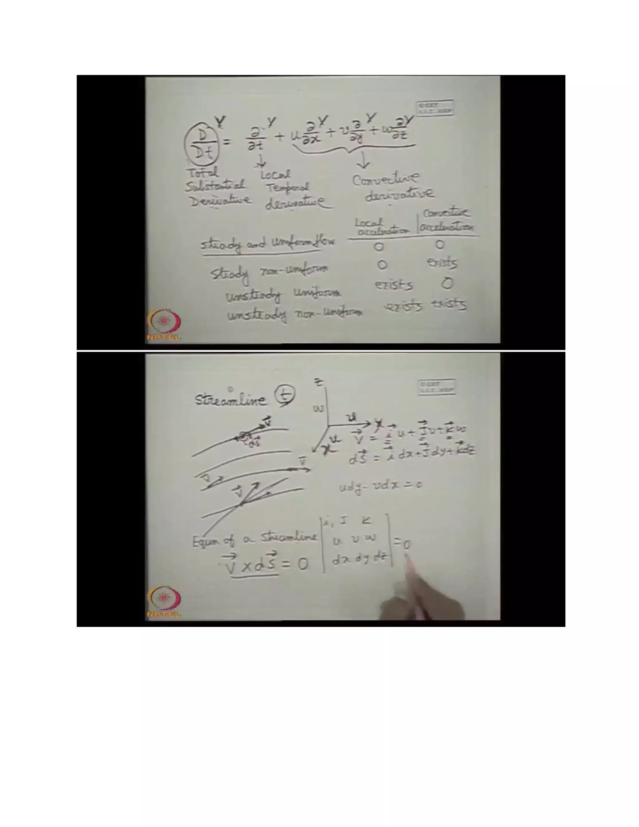
6. Flow along a streamline: Strictly speaking, the Bernoulli equation is applicable along a streamline,
and the value of the constant C is generally different for different streamlines. However, when a
region of the flow is irrotational and there is no vorticity in the flow field, the value of the constant
C remains the same for all streamlines, and the Bernoulli equation becomes applicable across
streamlines as well. Therefore, we do not need to be concerned about the streamlines when the
flow is irrotational, and we can apply the Bernoulli equation between any two points in the
irrotational region of the flow.
Frictional effects, heat transfer, and components that disturb the streamlined structure of flow
make the Bernoulli equation invalid. It should not be used in any of the flows shown here.
Hydraulic Grade Line (HGL) and Energy Grade Line (EGL)
INTERNAL FLOW
For internal flow in pipes:
In pipes:
The thickness of the boundary layer increases in the flow direction until the boundary layer
reaches the pipe center and thus fills the entire pipe and the velocity becomes fully developed a
little farther downstream. The region from the pipe inlet to the point at which the velocity profile
is fully developed is called the hydrodynamic entrance region, and the length of this region is called
the hydrodynamic entry length Lh. Flow in the entrance region is called hydrodynamically
developing flow since this is the region where the velocity profile develops. The region beyond the
entrance region in which the velocity profile is fully developed and remains unchanged is called
the hydrodynamically fully developed region. The flow is said to be fully developed
The shear stress at the pipe wall is related to the slope of the velocity profile at the surface. Noting
that the velocity profile remains unchanged in the hydrodynamically fully developed region, the
wall shear stress also remains constant in that region.
Consider fluid flow in the hydrodynamic entrance region of a pipe. The wall shear stress is
the highest at the pipe inlet where the thickness of the boundary layer is smallest, and decreases
gradually to the fully developed value. Therefore, the pressure drop is higher in the entrance
regions of a pipe, and the effect of the entrance region is always to increase the average friction
factor for the entire pipe. This increase may be significant for short pipes but is negligible for long
ones.
In fully developed laminar flow, each fluid particle moves at a constant axial velocity along
a streamline and the velocity profile u(r) remains unchanged in the flow direction. There is no
motion in the radial direction, and thus the velocity component in the direction normal to the pipe
axis is everywhere zero. There is no acceleration since the flow is steady and fully developed.
In laminar flow, fluid particles flow in an orderly manner along pathlines, and momentum and
energy are transferred across streamlines by molecular diffusion. In turbulent flow, the swirling
eddies transport mass, momentum, and energy to other regions of flow much more rapidly than
molecular diffusion, greatly enhancing mass, momentum, and heat transfer. As a result, turbulent
flow is associated with much higher values of friction, heat transfer, and mass transfer coefficients.
In turbulent flow despite the small thickness of the viscous sub-layer (usually much less than 1
percent of the pipe diameter), the characteristics of the flow in this layer are very important since
they set the stage for flow in the rest of the pipe. Any irregularity or roughness on the surface
disturbs this layer and affects the flow. Therefore, unlike laminar flow, the friction factor in
turbulent flow is a strong function of surface roughness. It should be kept in mind that roughness
is a relative concept, and it has significance when its height e is comparable to the thickness of the
viscous sub-layer (which is a function of the Reynolds number). All materials appear “rough” under
a microscope with sufficient magnification. In fluid mechanics, a surface is characterized as being
rough when the hills of roughness protrude out of the viscous sub-layer. A surface is said to be
hydrodynamically smooth when the sub-layer submerges the roughness elements. Glass and
plastic surfaces are generally considered to be hydrodynamically smooth.
The Moody Chart and the Colebrook Equation
The friction factor in fully developed turbulent pipe flow depends on the Reynolds number and
the relative roughness e/D, which is the ratio of the mean height of roughness of the pipe to the
pipe diameter.
The force a flowing fluid exerts on a body in the flow direction is called drag.
A stationary fluid exerts only normal pressure forces on the surface of a body immersed in it. A
moving fluid, however, also exerts tangential shear forces on the surface because of the no-slip
condition caused by viscous effects. Both of these forces, in general, have components in the
direction of flow, and thus the drag force is due to the combined effects of pressure and wall shear
forces in the flow direction. The components of the pressure and wall shear forces in the direction
normal to the flow tend to move the body in that direction, and their sum is called lift.
Both the skin friction (wall shear) and pressure, in general, contribute to the drag and the
lift. If the flat plate is tilted at an angle relative to the flow direction, then the drag force depends
on both the pressure and the shear stress.
The wings of airplanes are shaped and positioned specifically to generate lift with minimal
drag. This is done by maintaining an angle of attack during cruising. Both lift and drag are strong
functions of the angle of attack. The pressure difference between the top and bottom surfaces of
the wing generates an upward force that tends to lift the wing and thus the airplane to which it is
connected.
For slender bodies such as wings, the shear force acts nearly parallel to the flow direction,
and thus its contribution to the lift is small. The drag force for such slender bodies is mostly due
to shear forces (the skin friction). The drag and lift forces depend on the density of the fluid, the
upstream velocity V, and the size, shape, and orientation of the body. It is more convenient to
work with appropriate dimensionless numbers that represent the drag and lift characteristics of
the body. These numbers are the drag coefficient CD, and the lift coefficient CL, and they are defined
as
Where A is ordinarily the frontal area (the area projected on a plane normal to the direction of
flow) of the body.
The forces acting on a falling body are usually the drag force, the buoyant force, and the
weight of the body. When a body is dropped into the atmosphere or a lake, it first accelerates
under the influence of its weight. The motion of the body is resisted by the drag force, which acts
in the direction opposite to motion. As the velocity of the body increases, so does the drag force.
This continues until all the forces balance each other and the net force acting on the body (and
thus its acceleration) is zero. Then the velocity of the body remains constant during the rest of its
fall if the properties of the fluid in the path of the body remain essentially constant. This is the
maximum velocity a falling body can attain and is called the terminal velocity.
The Reynolds number is inversely proportional to the viscosity of the fluid. Therefore, the
contribution of friction drag to total drag for blunt bodies is less at higher Reynolds numbers and
may be negligible at very high Reynolds numbers. The drag in such cases is mostly due to pressure
drag.
At low Reynolds numbers, most drag is due to friction drag. This is especially the case for
highly streamlined bodies such as airfoils. The friction drag is also proportional to the surface area.
Therefore, bodies with a larger surface area experience a larger friction drag. Large commercial
airplanes, for example, reduce their total surface area and thus their drag by retracting their wing
extensions when they reach cruising altitudes to save fuel.
The friction drag coefficient is independent of surface roughness in laminar flow, but is a
strong function of surface roughness in turbulent flow due to surface roughness elements
protruding further into the boundary layer. The friction drag coefficient is analogous to the friction
factor in pipe flow.
Reducing Drag by Streamlining
The first thought that comes to mind to reduce drag is to streamline a body in order to reduce
flow separation and thus to reduce pressure drag. Even car salespeople are quick to point out the
low drag coefficients of their cars, owing to streamlining. But streamlining has opposite effects on
pressure and friction drag forces. It decreases pressure drag by delaying boundary layer separation
and thus reducing the pressure difference between the front and back of the body and increases
the friction drag by increasing the surface area. The end result depends on which effect dominates.
Therefore, any optimization study to reduce the drag of a body must consider both effects and
must attempt to minimize the sum of the two.
Streamlining has the added benefit of reducing vibration and noise. Streamlining should be
considered only for bluff bodies that are subjected to high-velocity fluid flow (and thus high
Reynolds numbers) for which flow separation is a real possibility. It is not necessary for bodies that
typically involve low Reynolds number flows (e.g., creeping flows in which Re < 1), since the drag
in those cases is almost entirely due to friction drag, and streamlining would only increase the
surface area and thus the total drag. Therefore, careless streamlining may actually increase drag
instead of decreasing it.
Effect of Surface Roughness
We mentioned earlier that surface roughness, in general, increases the drag coefficient in
turbulent flow. This is especially the case for streamlined bodies. For blunt bodies such as a circular
cylinder or sphere, however an increase in the surface roughness may actually decrease the drag
coefficient for a sphere. This is done by tripping the boundary layer into turbulence at a lower
Reynolds number, and thus delaying flow separation, causing the fluid to close in behind the body,
narrowing the wake, and reducing pressure drag considerably. This results in a much smaller drag
coefficient and thus drag force for a rough-surfaced cylinder or sphere in a certain range of
Reynolds number compared to a smooth one of identical size at the same velocity.
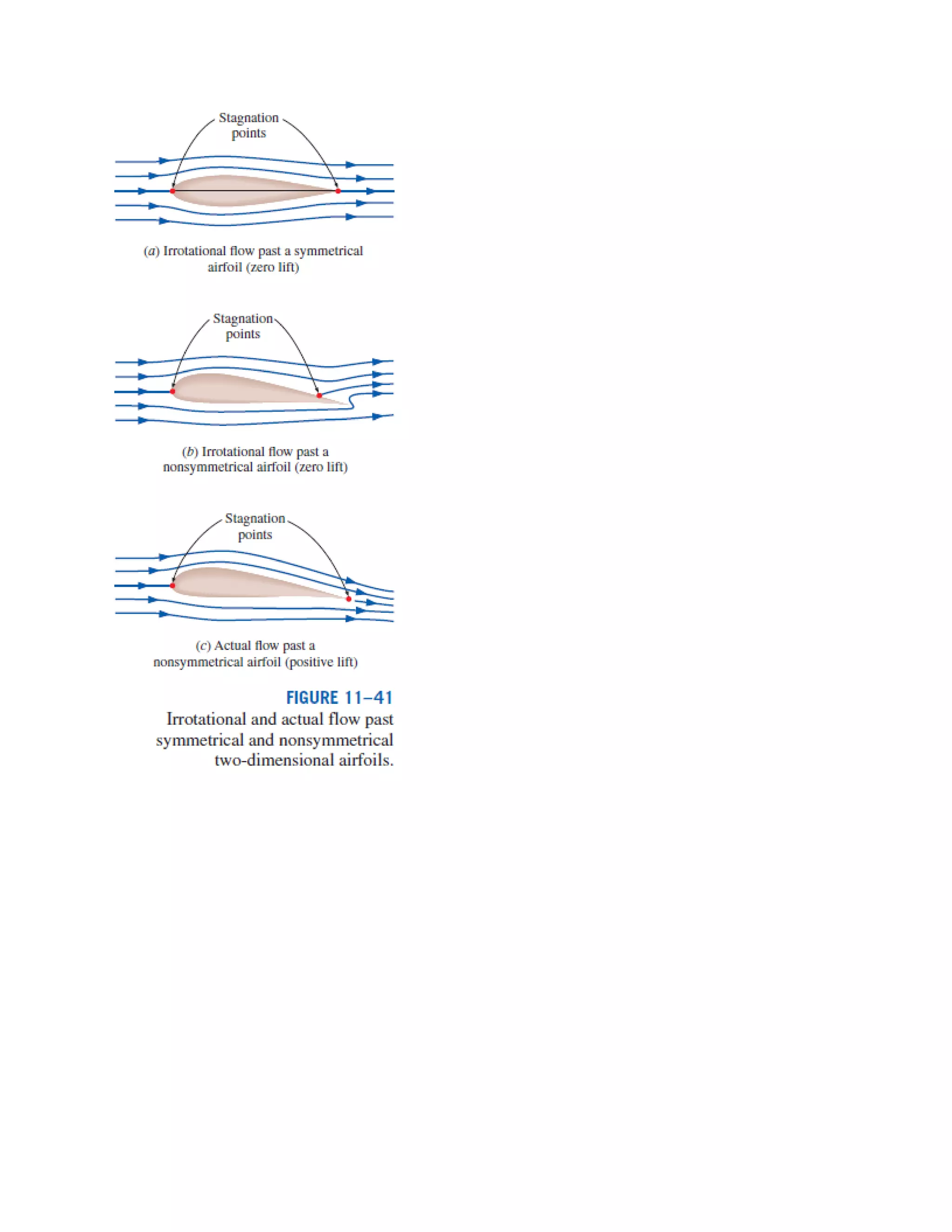
Lift is the component of the net force (due to viscous and pressure forces) that is perpendicular to
the flow direction, and the lift coefficient.
Therefore, lift in practice can be approximated as due entirely to the pressure distribution
on the surfaces of the body, and thus the shape of the body has the primary influence on lift. Then
the primary consideration in the design of airfoils is minimizing the average pressure at the upper
surface while maximizing it at the lower surface. The Bernoulli equation can be used as a guide in
identifying the high- and low-pressure regions: Pressure is low at locations where the flow velocity
is high, and pressure is high at locations where the flow velocity is low. Also, at moderate angles of
attack, lift is practically independent of the surface roughness since roughness affects the wall
shear, not the pressure. The contribution of shear to lift is significant only for very small
(lightweight) bodies that fly at low velocities (and thus low Reynolds numbers).
Fluid mechanics Cengel and Cimbala + NPTEL

More Related Content

What's hot

What's hot (20)

Introduction to fluid mechanics
Introduction to fluid mechanicsIntroduction to fluid mechanics
Introduction to fluid mechanics
 
FLUID MECHANICS
FLUID MECHANICSFLUID MECHANICS
FLUID MECHANICS
 
cengel-fluid mechanics
cengel-fluid mechanicscengel-fluid mechanics
cengel-fluid mechanics
 
Fluid statics
Fluid staticsFluid statics
Fluid statics
 
Types of fluid flow best ppt
Types of fluid flow best pptTypes of fluid flow best ppt
Types of fluid flow best ppt
 
Fluid dynamic
Fluid dynamicFluid dynamic
Fluid dynamic
 
Fluid mechanics lectur notes
Fluid mechanics lectur notesFluid mechanics lectur notes
Fluid mechanics lectur notes
 
Fluids and their properties
Fluids and their propertiesFluids and their properties
Fluids and their properties
 
Dimensionless analysis & Similarities
Dimensionless analysis & Similarities Dimensionless analysis & Similarities
Dimensionless analysis & Similarities
 
Fluid Kinematics
Fluid KinematicsFluid Kinematics
Fluid Kinematics
 
Dimension less numbers in applied fluid mechanics
Dimension less numbers in applied fluid mechanicsDimension less numbers in applied fluid mechanics
Dimension less numbers in applied fluid mechanics
 
Water hammer
Water hammerWater hammer
Water hammer
 
Fluid Mechanics - Fluid Dynamics
Fluid Mechanics - Fluid DynamicsFluid Mechanics - Fluid Dynamics
Fluid Mechanics - Fluid Dynamics
 
FLUID MECHANICS AND HYDRAULIC MACHINES
FLUID MECHANICS AND HYDRAULIC MACHINES FLUID MECHANICS AND HYDRAULIC MACHINES
FLUID MECHANICS AND HYDRAULIC MACHINES
 
Head losses
Head lossesHead losses
Head losses
 
Fluid Dynamics
Fluid DynamicsFluid Dynamics
Fluid Dynamics
 
Turbulent flow
Turbulent flowTurbulent flow
Turbulent flow
 
Fluid mechanics-ppt
Fluid mechanics-pptFluid mechanics-ppt
Fluid mechanics-ppt
 
Types of fluid flow
Types of fluid flowTypes of fluid flow
Types of fluid flow
 
S3 Chapter 2 Fluid Pressure
S3 Chapter 2 Fluid PressureS3 Chapter 2 Fluid Pressure
S3 Chapter 2 Fluid Pressure
 

Similar to Fluid mechanics Cengel and Cimbala + NPTEL

Fluid flow phenomenon, prepared by Makhdoom ibad ullah hashmi
Fluid flow phenomenon, prepared by Makhdoom ibad ullah hashmiFluid flow phenomenon, prepared by Makhdoom ibad ullah hashmi
Fluid flow phenomenon, prepared by Makhdoom ibad ullah hashmiUniversity of Gujrat, Pakistan
 
Fluid flow and mass transfer
Fluid flow and mass transferFluid flow and mass transfer
Fluid flow and mass transferPharmacy Universe
 
year one mech fluid Rev sheet
year one mech fluid Rev sheetyear one mech fluid Rev sheet
year one mech fluid Rev sheetdr walid
 
Kuliah thermofluid ke vii
Kuliah thermofluid ke viiKuliah thermofluid ke vii
Kuliah thermofluid ke viiAdi Winarta
 
22210003madhuraMahabal.pptxzsdrgzsrjdfjzdtj
22210003madhuraMahabal.pptxzsdrgzsrjdfjzdtj22210003madhuraMahabal.pptxzsdrgzsrjdfjzdtj
22210003madhuraMahabal.pptxzsdrgzsrjdfjzdtj22210007LAMKANEONKAR
 
Chapter1 fm-introduction to fluid mechanics-converted
Chapter1  fm-introduction to fluid mechanics-convertedChapter1  fm-introduction to fluid mechanics-converted
Chapter1 fm-introduction to fluid mechanics-convertedSatishkumarP9
 
Two Phase Flow Research
Two Phase Flow ResearchTwo Phase Flow Research
Two Phase Flow ResearchRex Liu
 
FLUID - Copy.ppt
FLUID - Copy.pptFLUID - Copy.ppt
FLUID - Copy.pptmiligroup
 
Fluid Mechanics lectures slides 1-30.pdf
Fluid Mechanics  lectures slides 1-30.pdfFluid Mechanics  lectures slides 1-30.pdf
Fluid Mechanics lectures slides 1-30.pdfBHAGVATAWARGAND
 
Fluid flow phenomena
Fluid flow phenomenaFluid flow phenomena
Fluid flow phenomenaRupak Bhowmik
 
Mekanika Fluida 1 P2. Oke.pdf, Presentasi kuliah pertemuan 2 untuk mata kulia...
Mekanika Fluida 1 P2. Oke.pdf, Presentasi kuliah pertemuan 2 untuk mata kulia...Mekanika Fluida 1 P2. Oke.pdf, Presentasi kuliah pertemuan 2 untuk mata kulia...
Mekanika Fluida 1 P2. Oke.pdf, Presentasi kuliah pertemuan 2 untuk mata kulia...ujiburrahman2
 

Similar to Fluid mechanics Cengel and Cimbala + NPTEL (20)

Rev sheet
Rev sheetRev sheet
Rev sheet
 
Types of fluid flow
Types of fluid flowTypes of fluid flow
Types of fluid flow
 
Fluid flow phenomenon, prepared by Makhdoom ibad ullah hashmi
Fluid flow phenomenon, prepared by Makhdoom ibad ullah hashmiFluid flow phenomenon, prepared by Makhdoom ibad ullah hashmi
Fluid flow phenomenon, prepared by Makhdoom ibad ullah hashmi
 
Fluid flow and mass transfer
Fluid flow and mass transferFluid flow and mass transfer
Fluid flow and mass transfer
 
section 1.pdf
section 1.pdfsection 1.pdf
section 1.pdf
 
year one mech fluid Rev sheet
year one mech fluid Rev sheetyear one mech fluid Rev sheet
year one mech fluid Rev sheet
 
Kuliah thermofluid ke vii
Kuliah thermofluid ke viiKuliah thermofluid ke vii
Kuliah thermofluid ke vii
 
22210003madhuraMahabal.pptxzsdrgzsrjdfjzdtj
22210003madhuraMahabal.pptxzsdrgzsrjdfjzdtj22210003madhuraMahabal.pptxzsdrgzsrjdfjzdtj
22210003madhuraMahabal.pptxzsdrgzsrjdfjzdtj
 
FM-I all slides.pdf
FM-I all slides.pdfFM-I all slides.pdf
FM-I all slides.pdf
 
Chapter1 fm-introduction to fluid mechanics-converted
Chapter1  fm-introduction to fluid mechanics-convertedChapter1  fm-introduction to fluid mechanics-converted
Chapter1 fm-introduction to fluid mechanics-converted
 
Pipe branching system and Revision
 Pipe branching system and Revision  Pipe branching system and Revision
Pipe branching system and Revision
 
Ppt-FM.pdf
Ppt-FM.pdfPpt-FM.pdf
Ppt-FM.pdf
 
Fluid
FluidFluid
Fluid
 
Two Phase Flow Research
Two Phase Flow ResearchTwo Phase Flow Research
Two Phase Flow Research
 
FLUID - Copy.ppt
FLUID - Copy.pptFLUID - Copy.ppt
FLUID - Copy.ppt
 
Fluid Mechanics lectures slides 1-30.pdf
Fluid Mechanics  lectures slides 1-30.pdfFluid Mechanics  lectures slides 1-30.pdf
Fluid Mechanics lectures slides 1-30.pdf
 
Fluid flow phenomena
Fluid flow phenomenaFluid flow phenomena
Fluid flow phenomena
 
Lecture2.pptx
Lecture2.pptxLecture2.pptx
Lecture2.pptx
 
Mekanika Fluida 1 P2. Oke.pdf, Presentasi kuliah pertemuan 2 untuk mata kulia...
Mekanika Fluida 1 P2. Oke.pdf, Presentasi kuliah pertemuan 2 untuk mata kulia...Mekanika Fluida 1 P2. Oke.pdf, Presentasi kuliah pertemuan 2 untuk mata kulia...
Mekanika Fluida 1 P2. Oke.pdf, Presentasi kuliah pertemuan 2 untuk mata kulia...
 
AVI.pptx
AVI.pptxAVI.pptx
AVI.pptx
 

Recently uploaded

Architect Hassan Khalil Portfolio for 2024
Architect Hassan Khalil Portfolio for 2024Architect Hassan Khalil Portfolio for 2024
Architect Hassan Khalil Portfolio for 2024hassan khalil
 
OSVC_Meta-Data based Simulation Automation to overcome Verification Challenge...
OSVC_Meta-Data based Simulation Automation to overcome Verification Challenge...OSVC_Meta-Data based Simulation Automation to overcome Verification Challenge...
OSVC_Meta-Data based Simulation Automation to overcome Verification Challenge...Soham Mondal
 
Call Girls Service Nagpur Tanvi Call 7001035870 Meet With Nagpur Escorts
Call Girls Service Nagpur Tanvi Call 7001035870 Meet With Nagpur EscortsCall Girls Service Nagpur Tanvi Call 7001035870 Meet With Nagpur Escorts
Call Girls Service Nagpur Tanvi Call 7001035870 Meet With Nagpur EscortsCall Girls in Nagpur High Profile
 
(ANVI) Koregaon Park Call Girls Just Call 7001035870 [ Cash on Delivery ] Pun...
(ANVI) Koregaon Park Call Girls Just Call 7001035870 [ Cash on Delivery ] Pun...(ANVI) Koregaon Park Call Girls Just Call 7001035870 [ Cash on Delivery ] Pun...
(ANVI) Koregaon Park Call Girls Just Call 7001035870 [ Cash on Delivery ] Pun...ranjana rawat
 
(SHREYA) Chakan Call Girls Just Call 7001035870 [ Cash on Delivery ] Pune Esc...
(SHREYA) Chakan Call Girls Just Call 7001035870 [ Cash on Delivery ] Pune Esc...(SHREYA) Chakan Call Girls Just Call 7001035870 [ Cash on Delivery ] Pune Esc...
(SHREYA) Chakan Call Girls Just Call 7001035870 [ Cash on Delivery ] Pune Esc...ranjana rawat
 
High Profile Call Girls Nagpur Meera Call 7001035870 Meet With Nagpur Escorts
High Profile Call Girls Nagpur Meera Call 7001035870 Meet With Nagpur EscortsHigh Profile Call Girls Nagpur Meera Call 7001035870 Meet With Nagpur Escorts
High Profile Call Girls Nagpur Meera Call 7001035870 Meet With Nagpur EscortsCall Girls in Nagpur High Profile
 
Software Development Life Cycle By Team Orange (Dept. of Pharmacy)
Software Development Life Cycle By  Team Orange (Dept. of Pharmacy)Software Development Life Cycle By  Team Orange (Dept. of Pharmacy)
Software Development Life Cycle By Team Orange (Dept. of Pharmacy)Suman Mia
 
SPICE PARK APR2024 ( 6,793 SPICE Models )
SPICE PARK APR2024 ( 6,793 SPICE Models )SPICE PARK APR2024 ( 6,793 SPICE Models )
SPICE PARK APR2024 ( 6,793 SPICE Models )Tsuyoshi Horigome
 
Sheet Pile Wall Design and Construction: A Practical Guide for Civil Engineer...
Sheet Pile Wall Design and Construction: A Practical Guide for Civil Engineer...Sheet Pile Wall Design and Construction: A Practical Guide for Civil Engineer...
Sheet Pile Wall Design and Construction: A Practical Guide for Civil Engineer...Dr.Costas Sachpazis
 
Introduction to Multiple Access Protocol.pptx
Introduction to Multiple Access Protocol.pptxIntroduction to Multiple Access Protocol.pptx
Introduction to Multiple Access Protocol.pptxupamatechverse
 
Microscopic Analysis of Ceramic Materials.pptx
Microscopic Analysis of Ceramic Materials.pptxMicroscopic Analysis of Ceramic Materials.pptx
Microscopic Analysis of Ceramic Materials.pptxpurnimasatapathy1234
 
VIP Call Girls Service Kondapur Hyderabad Call +91-8250192130
VIP Call Girls Service Kondapur Hyderabad Call +91-8250192130VIP Call Girls Service Kondapur Hyderabad Call +91-8250192130
VIP Call Girls Service Kondapur Hyderabad Call +91-8250192130Suhani Kapoor
 
(MEERA) Dapodi Call Girls Just Call 7001035870 [ Cash on Delivery ] Pune Escorts
(MEERA) Dapodi Call Girls Just Call 7001035870 [ Cash on Delivery ] Pune Escorts(MEERA) Dapodi Call Girls Just Call 7001035870 [ Cash on Delivery ] Pune Escorts
(MEERA) Dapodi Call Girls Just Call 7001035870 [ Cash on Delivery ] Pune Escortsranjana rawat
 
Decoding Kotlin - Your guide to solving the mysterious in Kotlin.pptx
Decoding Kotlin - Your guide to solving the mysterious in Kotlin.pptxDecoding Kotlin - Your guide to solving the mysterious in Kotlin.pptx
Decoding Kotlin - Your guide to solving the mysterious in Kotlin.pptxJoão Esperancinha
 
MANUFACTURING PROCESS-II UNIT-5 NC MACHINE TOOLS
MANUFACTURING PROCESS-II UNIT-5 NC MACHINE TOOLSMANUFACTURING PROCESS-II UNIT-5 NC MACHINE TOOLS
MANUFACTURING PROCESS-II UNIT-5 NC MACHINE TOOLSSIVASHANKAR N
 
Introduction to IEEE STANDARDS and its different types.pptx
Introduction to IEEE STANDARDS and its different types.pptxIntroduction to IEEE STANDARDS and its different types.pptx
Introduction to IEEE STANDARDS and its different types.pptxupamatechverse
 
Model Call Girl in Narela Delhi reach out to us at 🔝8264348440🔝
Model Call Girl in Narela Delhi reach out to us at 🔝8264348440🔝Model Call Girl in Narela Delhi reach out to us at 🔝8264348440🔝
Model Call Girl in Narela Delhi reach out to us at 🔝8264348440🔝soniya singh
 

Recently uploaded (20)

Architect Hassan Khalil Portfolio for 2024
Architect Hassan Khalil Portfolio for 2024Architect Hassan Khalil Portfolio for 2024
Architect Hassan Khalil Portfolio for 2024
 
OSVC_Meta-Data based Simulation Automation to overcome Verification Challenge...
OSVC_Meta-Data based Simulation Automation to overcome Verification Challenge...OSVC_Meta-Data based Simulation Automation to overcome Verification Challenge...
OSVC_Meta-Data based Simulation Automation to overcome Verification Challenge...
 
Call Girls Service Nagpur Tanvi Call 7001035870 Meet With Nagpur Escorts
Call Girls Service Nagpur Tanvi Call 7001035870 Meet With Nagpur EscortsCall Girls Service Nagpur Tanvi Call 7001035870 Meet With Nagpur Escorts
Call Girls Service Nagpur Tanvi Call 7001035870 Meet With Nagpur Escorts
 
Call Us -/9953056974- Call Girls In Vikaspuri-/- Delhi NCR
Call Us -/9953056974- Call Girls In Vikaspuri-/- Delhi NCRCall Us -/9953056974- Call Girls In Vikaspuri-/- Delhi NCR
Call Us -/9953056974- Call Girls In Vikaspuri-/- Delhi NCR
 
(ANVI) Koregaon Park Call Girls Just Call 7001035870 [ Cash on Delivery ] Pun...
(ANVI) Koregaon Park Call Girls Just Call 7001035870 [ Cash on Delivery ] Pun...(ANVI) Koregaon Park Call Girls Just Call 7001035870 [ Cash on Delivery ] Pun...
(ANVI) Koregaon Park Call Girls Just Call 7001035870 [ Cash on Delivery ] Pun...
 
(SHREYA) Chakan Call Girls Just Call 7001035870 [ Cash on Delivery ] Pune Esc...
(SHREYA) Chakan Call Girls Just Call 7001035870 [ Cash on Delivery ] Pune Esc...(SHREYA) Chakan Call Girls Just Call 7001035870 [ Cash on Delivery ] Pune Esc...
(SHREYA) Chakan Call Girls Just Call 7001035870 [ Cash on Delivery ] Pune Esc...
 
High Profile Call Girls Nagpur Meera Call 7001035870 Meet With Nagpur Escorts
High Profile Call Girls Nagpur Meera Call 7001035870 Meet With Nagpur EscortsHigh Profile Call Girls Nagpur Meera Call 7001035870 Meet With Nagpur Escorts
High Profile Call Girls Nagpur Meera Call 7001035870 Meet With Nagpur Escorts
 
Software Development Life Cycle By Team Orange (Dept. of Pharmacy)
Software Development Life Cycle By  Team Orange (Dept. of Pharmacy)Software Development Life Cycle By  Team Orange (Dept. of Pharmacy)
Software Development Life Cycle By Team Orange (Dept. of Pharmacy)
 
SPICE PARK APR2024 ( 6,793 SPICE Models )
SPICE PARK APR2024 ( 6,793 SPICE Models )SPICE PARK APR2024 ( 6,793 SPICE Models )
SPICE PARK APR2024 ( 6,793 SPICE Models )
 
Sheet Pile Wall Design and Construction: A Practical Guide for Civil Engineer...
Sheet Pile Wall Design and Construction: A Practical Guide for Civil Engineer...Sheet Pile Wall Design and Construction: A Practical Guide for Civil Engineer...
Sheet Pile Wall Design and Construction: A Practical Guide for Civil Engineer...
 
Introduction to Multiple Access Protocol.pptx
Introduction to Multiple Access Protocol.pptxIntroduction to Multiple Access Protocol.pptx
Introduction to Multiple Access Protocol.pptx
 
★ CALL US 9953330565 ( HOT Young Call Girls In Badarpur delhi NCR
★ CALL US 9953330565 ( HOT Young Call Girls In Badarpur delhi NCR★ CALL US 9953330565 ( HOT Young Call Girls In Badarpur delhi NCR
★ CALL US 9953330565 ( HOT Young Call Girls In Badarpur delhi NCR
 
Microscopic Analysis of Ceramic Materials.pptx
Microscopic Analysis of Ceramic Materials.pptxMicroscopic Analysis of Ceramic Materials.pptx
Microscopic Analysis of Ceramic Materials.pptx
 
VIP Call Girls Service Kondapur Hyderabad Call +91-8250192130
VIP Call Girls Service Kondapur Hyderabad Call +91-8250192130VIP Call Girls Service Kondapur Hyderabad Call +91-8250192130
VIP Call Girls Service Kondapur Hyderabad Call +91-8250192130
 
(MEERA) Dapodi Call Girls Just Call 7001035870 [ Cash on Delivery ] Pune Escorts
(MEERA) Dapodi Call Girls Just Call 7001035870 [ Cash on Delivery ] Pune Escorts(MEERA) Dapodi Call Girls Just Call 7001035870 [ Cash on Delivery ] Pune Escorts
(MEERA) Dapodi Call Girls Just Call 7001035870 [ Cash on Delivery ] Pune Escorts
 
Decoding Kotlin - Your guide to solving the mysterious in Kotlin.pptx
Decoding Kotlin - Your guide to solving the mysterious in Kotlin.pptxDecoding Kotlin - Your guide to solving the mysterious in Kotlin.pptx
Decoding Kotlin - Your guide to solving the mysterious in Kotlin.pptx
 
MANUFACTURING PROCESS-II UNIT-5 NC MACHINE TOOLS
MANUFACTURING PROCESS-II UNIT-5 NC MACHINE TOOLSMANUFACTURING PROCESS-II UNIT-5 NC MACHINE TOOLS
MANUFACTURING PROCESS-II UNIT-5 NC MACHINE TOOLS
 
Introduction to IEEE STANDARDS and its different types.pptx
Introduction to IEEE STANDARDS and its different types.pptxIntroduction to IEEE STANDARDS and its different types.pptx
Introduction to IEEE STANDARDS and its different types.pptx
 
Exploring_Network_Security_with_JA3_by_Rakesh Seal.pptx
Exploring_Network_Security_with_JA3_by_Rakesh Seal.pptxExploring_Network_Security_with_JA3_by_Rakesh Seal.pptx
Exploring_Network_Security_with_JA3_by_Rakesh Seal.pptx
 
Model Call Girl in Narela Delhi reach out to us at 🔝8264348440🔝
Model Call Girl in Narela Delhi reach out to us at 🔝8264348440🔝Model Call Girl in Narela Delhi reach out to us at 🔝8264348440🔝
Model Call Girl in Narela Delhi reach out to us at 🔝8264348440🔝
 

Fluid mechanics Cengel and Cimbala + NPTEL

  • 1. Fluid Mechanics – Cengel and Cimbala + NPTEL (Condensed) A solid can resist an applied shear stress by deforming, whereas a fluid deforms continuously under the influence of a shear stress, no matter how small. In solids, stress is proportional to strain, but in fluids, stress is proportional to strain rate. When a constant shear force is applied, a solid eventually stops deforming at some fixed strain angle, whereas a fluid never stops deforming and approaches a constant rate of strain. Particularly at low densities, the intermolecular forces are very small, and collisions are the only mode of interaction between the molecules. Molecules in the gas phase are at a considerably higher energy level than they are in the liquid or solid phase. Therefore, the gas must release a large amount of its energy before it can condense or freeze. NO SLIP CONDITION Water in a river cannot flow through large rocks and must go around them. That is, the water velocity normal to the rock surface must be zero, and water approaching the surface normally comes to a complete stop at the surface. What is not as obvious is that water approaching the rock at any angle also comes to a complete stop at the rock surface, and thus the tangential velocity of water at the surface is also zero. That is, a fluid in direct contact with a solid “sticks” to the surface, and there is no slip. This is known as the no-slip condition. The fluid property responsible for the no-slip condition and the development of the boundary layer is viscosity. The no-slip condition is responsible for the development of the velocity profile. The flow region adjacent to the wall in which the viscous effects (and thus the velocity gradients) are significant is called the boundary layer. Another consequence of the no-slip condition is the surface drag, or skin friction drag, which is the force a fluid exerts on a surface in the flow direction. When a fluid is forced to flow over a curved surface, such as the back side of a cylinder, the boundary layer may no longer remain attached to the surface and separates from the surface—a process called flow separation. Compressible versus Incompressible Flow A flow is classified as being compressible or incompressible, depending on the level of variation of density during flow. Incompressibility is an approximation, in which the flow is said to be incompressible if the density remains nearly constant throughout. Therefore, the volume of every portion of fluid remains unchanged over the course of its motion when the flow is approximated as incompressible. The densities of liquids are essentially constant, and thus the flow of liquids is
  • 2. typically incompressible. Therefore, liquids are usually referred to as incompressible substances. A pressure of 210 atm, for example, causes the density of liquid water at 1 atm to change by just 1 percent. Gases, on the other hand, are highly compressible. A pressure change of just 0.01 atm, for example, causes a change of 1 percent in the density of atmospheric air. When analyzing rockets, spacecraft, and other systems that involve high-speed gas flows, the flow speed is often expressed in terms of the dimensionless Mach number defined as Where c is the speed of sound whose value is 346 m/s in air at room temperature at sea level. A flow is called Sonic when Ma = 1, subsonic when Ma<1, supersonic when Ma>1, and hypersonic when Ma>>1. Liquid flows are incompressible to a high level of accuracy, but the level of variation of density in gas flows and the consequent level of approximation made when modeling gas flows as incompressible depends on the Mach number. Gas flows can often be approximated as incompressible if the density changes are under about 5 percent, which is usually the case when Ma<0.3. Therefore, the compressibility effects of air at room temperature can be neglected at speeds under about 100 m/s. A typical fluid flow involves a three-dimensional geometry, and the velocity may vary in all three dimensions. However, the variation of velocity in certain directions can be small relative to the variation in other directions and can be ignored with negligible error. In such cases, the flow can be modeled conveniently as being one- or two-dimensional, which is easier to analyze. The dimensionality of the flow also depends on the choice of coordinate system and its orientation. The pipe flow discussed, for example, is one-dimensional in cylindrical coordinates, but two-dimensional in Cartesian coordinates.
  • 3. CONTINUUM A fluid is composed of molecules which may be widely spaced apart, especially in the gas phase. Yet it is convenient to disregard the atomic nature of the fluid and view it as continuous, homogeneous matter with no holes, that is, a continuum. The continuum idealization allows us to treat properties as point functions and to assume that the properties vary continually in space
  • 4. with no jump discontinuities. This idealization is valid as long as the size of the system we deal with is large relative to the space between the molecules. VAPOR PRESSURE AND CAVITATION At a given pressure, the temperature at which a pure substance changes phase is called the saturation temperature Tsat. Likewise, at a given temperature, the pressure at which a pure substance changes phase is called the saturation pressure Psat. The vapor pressure Pv of a pure substance is defined as the pressure exerted by its vapor in phase equilibrium with its liquid at a given temperature. Pv is a property of the pure substance, and turns out to be identical to the saturation pressure Psat of the liquid (Pv = Psat). The partial pressure of a vapor must be less than or equal to the vapor pressure if there is no liquid present. However, when both vapor and liquid are present and the system is in phase equilibrium, the partial pressure of the vapor must equal the vapor pressure, and the system is said to be saturated. The vapor pressure of water at 20°C is 2.34 kPa. Therefore, a bucket of water at 20°C left in a room with dry air at 1 atm will continue evaporating until one of two things happens: the water evaporates away (there is not enough water to establish phase equilibrium in the room), or the evaporation stops when the partial pressure of the water vapor in the room rises to 2.34 kPa at which point phase equilibrium is established. For phase-change processes between the liquid and vapor phases of a pure substance, the saturation pressure and the vapor pressure are equivalent since the vapor is pure. The pressure value would be the same whether it is measured in the vapor or liquid phase (provided that it is measured at a location close to the liquid–vapor interface to avoid any hydrostatic effects). Vapor pressure increases with temperature. Thus, a substance at higher pressure boils at higher temperature. For example, water boils at 134°C in a pressure cooker operating at 3 atm absolute pressure, but it boils at 93°C in an ordinary pan at a 2000-m elevation, where the atmospheric pressure is 0.8 atm. There is a possibility of the liquid pressure in liquid-flow systems dropping below the vapor pressure at some locations, and the resulting unplanned vaporization. For example, water at 10°C may vaporize and form bubbles at locations (such as the tip regions of impellers or suction sides of pumps) where the pressure drops below 1.23 kPa. The vapor bubbles (called cavitation bubbles
  • 5. since they form “cavities” in the liquid) collapse as they are swept away from the low-pressure regions, generating highly destructive, extremely high-pressure waves A large value of κ indicates that a large change in pressure is needed to cause a small fractional change in volume, and thus a fluid with a large k is essentially incompressible. This is typical for liquids, and explains why liquids are usually considered to be incompressible. Therefore, the coefficient of compressibility of an ideal gas is equal to its absolute pressure.
  • 6.
  • 7. The viscosity of a fluid depends on both temperature and pressure, although the dependence on pressure is rather weak. For liquids, both the dynamic and kinematic viscosities are practically independent of pressure, and any small variation with pressure is usually disregarded, except at extremely high pressures. For gases, this is also the case for dynamic viscosity (at low to moderate pressures), but not for kinematic viscosity since the density of a gas is proportional to its pressure.
  • 8. The viscosity of a fluid is a measure of its “resistance to deformation.” Viscosity is due to the internal frictional force that develops between different layers of fluids as they are forced to move relative to each other. The viscosity of a fluid is directly related to the pumping power needed to transport a fluid in a pipe or to move a body (such as a car in air or a submarine in the sea) through a fluid. Viscosity is caused by the cohesive forces between the molecules in liquids and by the molecular collisions in gases, and it varies greatly with temperature. The viscosity of liquids decreases with temperature, whereas the viscosity of gases increases with temperature. This is because in a liquid the molecules possess more energy at higher temperatures, and they can oppose the large cohesive intermolecular forces more strongly. As a result, the energized liquid molecules can move more freely. In a gas, on the other hand, the intermolecular forces are negligible, and the gas molecules at high temperatures move randomly at higher velocities. This results in more molecular collisions per unit volume per unit time and therefore in greater resistance to flow. SURFACE TENSION AND CAPILLARY EFFECT Therefore, there is a net attractive force acting on the molecule at the surface of the liquid, which tends to pull the molecules on the surface toward the interior of the liquid. This force is balanced by the repulsive forces from the molecules below the surface that are trying to be compressed. The result is that the liquid minimizes its surface area. This is the reason for the tendency of liquid droplets to attain a spherical shape, which has the minimum surface area for a given volume.
  • 9. A curved interface indicates a pressure difference (or “pressure jump”) across the interface with pressure being higher on the concave side. Consider, for example, a droplet of liquid in air, an air (or other gas) bubble in water, or a soap bubble in air. The excess pressure ΔP above atmospheric pressure can be determined by considering a free-body diagram of half the droplet or bubble (Fig. 2–34). Noting that surface tension acts along the circumference and the pressure acts on the area, horizontal force balances for the droplet or air bubble and the soap bubble give Capillary Effect Another consequence of surface tension is the capillary effect, which is the rise or fall of a liquid in a small-diameter tube inserted into the liquid. Such narrow tubes or confined flow channels are called capillaries.
  • 10. It is important to use sufficiently large tubes to minimize the capillary effect. The capillary rise is also inversely proportional to the density of the liquid, as expected. PRESSURE AND FLUID STATICS Pressure at a Point Pressure is the compressive force per unit area, and it gives the impression of being a vector. However, pressure at any point in a fluid is the same in all directions.
  • 11. Pressure in a fluid at rest is independent of the shape or cross section of the container. It changes with the vertical distance, but remains constant in other directions. Therefore, the pressure is the same at all points on a horizontal plane in a given fluid. A consequence of the pressure in a fluid remaining constant in the horizontal direction is that the pressure applied to a confined fluid increases the pressure throughout by the same amount. This is called Pascal’s law.
  • 12.
  • 13. In fluid statics, there is no relative motion between adjacent fluid layers, and thus there are no shear (tangential) stresses in the fluid trying to deform it. The only stress we deal with in fluid statics is the normal stress, which is the pressure, and the variation of pressure is due only to the weight of the fluid. Therefore, the topic of fluid statics has significance only in gravity fields, and the force relations developed naturally involve the gravitational acceleration g.
  • 14. if tube is inclined, difference in elevation measures piezometric head difference rather than just static pressure head difference between two points. to measure very low pressure difference, difference between working fluid and manometric fluid should be low as possible but at the same time we have to see proper meniscus formation which not possible fluids having nearly same density.
  • 15. above is a solution to show large deflection even for low pressure change. Geometrical magnification done by just providing inclination. Experimenter will measure the displacement of manometric fluid along the length of the tube.
  • 16. We do not make container transparent. But we cannot make theta so small that free surface will cause error in the measurement.
  • 17.
  • 18. The magnitude of the resultant force acting on a plane surface of a completely submerged plate in a homogeneous (constant density) fluid is equal to the product of the pressure PC at the centroid of the surface and the area A of the surface.
  • 19. Same force whether placed inclined or horizontal; point is vertical depth of horizontally placed plate should be same as the centre of area of inclined plate. When we discuss the hydrostatic forces of plates submerged, we assume other side is kind of atmospheric, because net force is zero on the plate. How could we say that the forces are acting. forces are parallel to each other in the case of flat plates, but in curved surfaces forces will act normal to the surface which are not parallel to each other. Therefore simple scalar summation is not possible here. Therefore we have to take components and add them in particular directions.
  • 20. We used to find the forces on submerged body and liquid is open to atmosphere. Technique: to find vertical component of force we have to calculate the weight of water above the body upto free surface of water. Now here there is no free surface that means we have to imagine whole system is immersed in the water the depth of system would be calculated using pressure head formula, as we know the pressure at the top inside the container.
  • 21. BUOYANCY (Thread from Physicsforums) If the person sitting in the boat throws a pebble to the swimming pool. Pebble was initially contained inside the boat and of course it has higher density than water. Consider the extreme case and the problem is much easier to understand; The boat is weightless and the pebble has close to infinite density. Now what I understood reading the complete thread. Boat is assumed weightless and stone is of finite density & some finite volume. Now only weight of stone will contribute in displacing certain volume of water. The proportion of density between water and pebble will decide how much volume (multiple of stone's volume) water will be displaced. As the weight of stone will be equal to the weight of displaced water I.e. Archimedes principle. Let's say the density of stone is 1000 times that of water. So when pebble is in the boat it will displace 1000 times more volume compared to the pebble sinking to the bottom of the pool. Because when pebble is sinking it is only displacing its own volume. So level of swimming pool will fall after throwing the pebble. center of buoyancy below center of gravity does not define the equilibrium is stable or unstable. How far B shifts after tilting will decide; whether it is restoring or non-restoring.
  • 22. If B shifts more than the vertical line of center of gravity then restoring couple is there. i.e. metacenter is above the center of gravity. Metacenter is the geometrical property.
  • 23. Time period is inversely proportional to the metacentric height which will cause discomfort to the passengers. Thus we sacrifice some stability to increase the time period. Centre of buoyancy shifts gives positive effect but think of if center of gravity changes somehow; cargo shifted to one side or ship is carrying liquid. Therefore there are large number of compartments to avoid deviation of free surfaces of liquid. Direct calculation of “y” in case of cylinder.
  • 24. Acceleration on a Straight Path
  • 25. ROTATION IN A CYLINDRICAL CONTAINER We know from experience that when a glass filled with water is rotated about its axis, the fluid is forced outward as a result of the so-called centrifugal force (but more properly explained in terms of centripetal acceleration), and the free surface of the liquid becomes concave. This is known as the forced vortex motion. Consider a vertical cylindrical container partially filled with a liquid. The container is now rotated about its axis at a constant angular velocity of v, as shown in Fig. 3–59. After initial transients, the liquid will move as a rigid body together with the container. There is no deformation, and thus there can be no shear stress, and every fluid particle in the container moves with the same angular velocity.
  • 26.
  • 27.
  • 28. The Bernoulli equation is obtained from Newton’s second law for a fluid particle moving along a streamline. It can also be obtained from the first law of thermodynamics applied to a steady-flow system. Some of the Limitations on the Use of the Bernoulli Equation 1. Steady flow: It is applicable to steady flow. Therefore, it should not be used during the transient start-up and shut-down periods, or during periods of change in the flow conditions. Note that there is an unsteady form of the Bernoulli equation 2. Negligible viscous effects: Every flow involves some friction, no matter how small, and frictional effects may or may not be negligible. The situation is complicated even more by the amount of error that can be tolerated. In general, frictional effects are negligible for short flow sections with large cross sections, especially at low flow velocities. Frictional effects are usually significant in
  • 29. long and narrow flow passages, in the wake region downstream of an object, and in diverging flow sections such as diffusers because of the increased possibility of the fluid separating from the walls in such geometries. Frictional effects are also significant near solid surfaces, and thus the Bernoulli equation is usually applicable along a streamline in the core region of the flow, but not along a streamline close to the surface. A component that disturbs the streamlined structure of flow and thus causes considerable mixing and backflow such as a sharp entrance of a tube or a partially closed valve in a flow section can make the Bernoulli equation inapplicable. 4. Incompressible flow: This condition is satisfied by liquids and also by gases at Mach numbers less than about 0.3 since compressibility effects and thus density variations of gases are negligible at such relatively low velocities. Note that there is a compressible form of the Bernoulli equation. 6. Flow along a streamline: Strictly speaking, the Bernoulli equation is applicable along a streamline, and the value of the constant C is generally different for different streamlines. However, when a region of the flow is irrotational and there is no vorticity in the flow field, the value of the constant C remains the same for all streamlines, and the Bernoulli equation becomes applicable across streamlines as well. Therefore, we do not need to be concerned about the streamlines when the flow is irrotational, and we can apply the Bernoulli equation between any two points in the irrotational region of the flow.
  • 30.
  • 31. Frictional effects, heat transfer, and components that disturb the streamlined structure of flow make the Bernoulli equation invalid. It should not be used in any of the flows shown here.
  • 32. Hydraulic Grade Line (HGL) and Energy Grade Line (EGL)
  • 33.
  • 35. For internal flow in pipes:
  • 36. In pipes: The thickness of the boundary layer increases in the flow direction until the boundary layer reaches the pipe center and thus fills the entire pipe and the velocity becomes fully developed a little farther downstream. The region from the pipe inlet to the point at which the velocity profile is fully developed is called the hydrodynamic entrance region, and the length of this region is called the hydrodynamic entry length Lh. Flow in the entrance region is called hydrodynamically developing flow since this is the region where the velocity profile develops. The region beyond the entrance region in which the velocity profile is fully developed and remains unchanged is called the hydrodynamically fully developed region. The flow is said to be fully developed The shear stress at the pipe wall is related to the slope of the velocity profile at the surface. Noting that the velocity profile remains unchanged in the hydrodynamically fully developed region, the wall shear stress also remains constant in that region. Consider fluid flow in the hydrodynamic entrance region of a pipe. The wall shear stress is the highest at the pipe inlet where the thickness of the boundary layer is smallest, and decreases gradually to the fully developed value. Therefore, the pressure drop is higher in the entrance regions of a pipe, and the effect of the entrance region is always to increase the average friction factor for the entire pipe. This increase may be significant for short pipes but is negligible for long ones. In fully developed laminar flow, each fluid particle moves at a constant axial velocity along a streamline and the velocity profile u(r) remains unchanged in the flow direction. There is no motion in the radial direction, and thus the velocity component in the direction normal to the pipe axis is everywhere zero. There is no acceleration since the flow is steady and fully developed.
  • 37.
  • 38.
  • 39. In laminar flow, fluid particles flow in an orderly manner along pathlines, and momentum and energy are transferred across streamlines by molecular diffusion. In turbulent flow, the swirling eddies transport mass, momentum, and energy to other regions of flow much more rapidly than molecular diffusion, greatly enhancing mass, momentum, and heat transfer. As a result, turbulent flow is associated with much higher values of friction, heat transfer, and mass transfer coefficients. In turbulent flow despite the small thickness of the viscous sub-layer (usually much less than 1 percent of the pipe diameter), the characteristics of the flow in this layer are very important since they set the stage for flow in the rest of the pipe. Any irregularity or roughness on the surface disturbs this layer and affects the flow. Therefore, unlike laminar flow, the friction factor in turbulent flow is a strong function of surface roughness. It should be kept in mind that roughness is a relative concept, and it has significance when its height e is comparable to the thickness of the viscous sub-layer (which is a function of the Reynolds number). All materials appear “rough” under a microscope with sufficient magnification. In fluid mechanics, a surface is characterized as being rough when the hills of roughness protrude out of the viscous sub-layer. A surface is said to be hydrodynamically smooth when the sub-layer submerges the roughness elements. Glass and plastic surfaces are generally considered to be hydrodynamically smooth. The Moody Chart and the Colebrook Equation The friction factor in fully developed turbulent pipe flow depends on the Reynolds number and the relative roughness e/D, which is the ratio of the mean height of roughness of the pipe to the pipe diameter.
  • 40. The force a flowing fluid exerts on a body in the flow direction is called drag. A stationary fluid exerts only normal pressure forces on the surface of a body immersed in it. A moving fluid, however, also exerts tangential shear forces on the surface because of the no-slip condition caused by viscous effects. Both of these forces, in general, have components in the direction of flow, and thus the drag force is due to the combined effects of pressure and wall shear forces in the flow direction. The components of the pressure and wall shear forces in the direction normal to the flow tend to move the body in that direction, and their sum is called lift. Both the skin friction (wall shear) and pressure, in general, contribute to the drag and the lift. If the flat plate is tilted at an angle relative to the flow direction, then the drag force depends on both the pressure and the shear stress. The wings of airplanes are shaped and positioned specifically to generate lift with minimal drag. This is done by maintaining an angle of attack during cruising. Both lift and drag are strong
  • 41. functions of the angle of attack. The pressure difference between the top and bottom surfaces of the wing generates an upward force that tends to lift the wing and thus the airplane to which it is connected. For slender bodies such as wings, the shear force acts nearly parallel to the flow direction, and thus its contribution to the lift is small. The drag force for such slender bodies is mostly due to shear forces (the skin friction). The drag and lift forces depend on the density of the fluid, the upstream velocity V, and the size, shape, and orientation of the body. It is more convenient to work with appropriate dimensionless numbers that represent the drag and lift characteristics of the body. These numbers are the drag coefficient CD, and the lift coefficient CL, and they are defined as Where A is ordinarily the frontal area (the area projected on a plane normal to the direction of flow) of the body. The forces acting on a falling body are usually the drag force, the buoyant force, and the weight of the body. When a body is dropped into the atmosphere or a lake, it first accelerates under the influence of its weight. The motion of the body is resisted by the drag force, which acts in the direction opposite to motion. As the velocity of the body increases, so does the drag force. This continues until all the forces balance each other and the net force acting on the body (and thus its acceleration) is zero. Then the velocity of the body remains constant during the rest of its fall if the properties of the fluid in the path of the body remain essentially constant. This is the maximum velocity a falling body can attain and is called the terminal velocity.
  • 42. The Reynolds number is inversely proportional to the viscosity of the fluid. Therefore, the contribution of friction drag to total drag for blunt bodies is less at higher Reynolds numbers and may be negligible at very high Reynolds numbers. The drag in such cases is mostly due to pressure drag. At low Reynolds numbers, most drag is due to friction drag. This is especially the case for highly streamlined bodies such as airfoils. The friction drag is also proportional to the surface area. Therefore, bodies with a larger surface area experience a larger friction drag. Large commercial airplanes, for example, reduce their total surface area and thus their drag by retracting their wing extensions when they reach cruising altitudes to save fuel. The friction drag coefficient is independent of surface roughness in laminar flow, but is a strong function of surface roughness in turbulent flow due to surface roughness elements protruding further into the boundary layer. The friction drag coefficient is analogous to the friction factor in pipe flow. Reducing Drag by Streamlining The first thought that comes to mind to reduce drag is to streamline a body in order to reduce flow separation and thus to reduce pressure drag. Even car salespeople are quick to point out the low drag coefficients of their cars, owing to streamlining. But streamlining has opposite effects on pressure and friction drag forces. It decreases pressure drag by delaying boundary layer separation and thus reducing the pressure difference between the front and back of the body and increases the friction drag by increasing the surface area. The end result depends on which effect dominates.
  • 43. Therefore, any optimization study to reduce the drag of a body must consider both effects and must attempt to minimize the sum of the two. Streamlining has the added benefit of reducing vibration and noise. Streamlining should be considered only for bluff bodies that are subjected to high-velocity fluid flow (and thus high Reynolds numbers) for which flow separation is a real possibility. It is not necessary for bodies that typically involve low Reynolds number flows (e.g., creeping flows in which Re < 1), since the drag in those cases is almost entirely due to friction drag, and streamlining would only increase the surface area and thus the total drag. Therefore, careless streamlining may actually increase drag instead of decreasing it.
  • 44.
  • 45. Effect of Surface Roughness We mentioned earlier that surface roughness, in general, increases the drag coefficient in turbulent flow. This is especially the case for streamlined bodies. For blunt bodies such as a circular cylinder or sphere, however an increase in the surface roughness may actually decrease the drag coefficient for a sphere. This is done by tripping the boundary layer into turbulence at a lower Reynolds number, and thus delaying flow separation, causing the fluid to close in behind the body, narrowing the wake, and reducing pressure drag considerably. This results in a much smaller drag coefficient and thus drag force for a rough-surfaced cylinder or sphere in a certain range of Reynolds number compared to a smooth one of identical size at the same velocity. Lift is the component of the net force (due to viscous and pressure forces) that is perpendicular to the flow direction, and the lift coefficient.
  • 46. Therefore, lift in practice can be approximated as due entirely to the pressure distribution on the surfaces of the body, and thus the shape of the body has the primary influence on lift. Then the primary consideration in the design of airfoils is minimizing the average pressure at the upper surface while maximizing it at the lower surface. The Bernoulli equation can be used as a guide in identifying the high- and low-pressure regions: Pressure is low at locations where the flow velocity is high, and pressure is high at locations where the flow velocity is low. Also, at moderate angles of attack, lift is practically independent of the surface roughness since roughness affects the wall shear, not the pressure. The contribution of shear to lift is significant only for very small (lightweight) bodies that fly at low velocities (and thus low Reynolds numbers).