Download to read offline
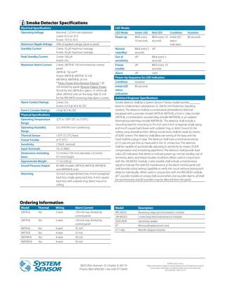

The document outlines the features and specifications of the System Sensor i3 series smoke detectors, which include a sounder and relay option. It emphasizes installation ease, intelligence, and instant inspection, showcasing features like a plug-in design, drift compensation, and remote maintenance signaling. Specifications for various models, including electrical and physical attributes, as well as ordering information, are also provided.