The document outlines the final project design for the Weyizero Wuha small scale irrigation diversion project by students of the Hydraulic and Water Resources Engineering department, detailing its location, hydrological analysis, hydraulic design, and cost estimations. The project aims to optimize water usage and land resources for agricultural growth in the South Gondar region of Ethiopia, thereby improving food security and economic conditions for local farmers. It includes multiple chapters covering project objectives, methodologies, data analysis, design considerations, and recommendations.


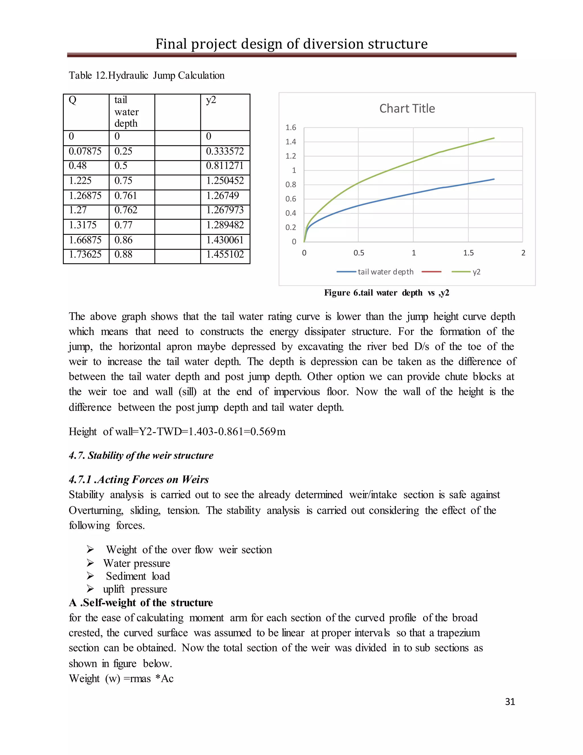
![Final project design of diversion structure
25
4.4.1. Irrigation Duty:
Irrigation duty is the volume of water required per hectare for the full flange of the crops; and it
is also the relationship between the volume of water and the area of the crop matures. It helps in
designing an efficient irrigation canal system. The area, which will be irrigated, can be calculated
by knowing the total available water at the source and the overall duty for all crops required to be
irrigated in different seasons of the years.
The proposed cropping pattern of the project has showed a maximum irrigation water
requirement (IWR) in the month of October (ADSWE, feasibility report). IWR has to be taken
for designing of the irrigation water application and the flows in the entire canal system.
However, here for the convenience of the designing and operation of the project, from all the
proposed crops the potato crop peak net irrigation water requirement (NIWR) has taken for the
irrigation project duty calculation. The potato peak NIWR is 6mm/day in the months of March &
two decades in April.
The gross irrigation water requirement (GIWR) is calculated by NIWR and irrigation efficiency:
GIWR = NIWR x IE
Where; GIWR – Gross irrigation water requirement [mm/day]
NIWR – Net irrigation water requirement [mm/day]
IE – Irrigation Efficiency [%]
e = ec × ea/100 = (60 × 80)/100=48% ≈ 50% Where, ea = scheme irrigation efficiency (%), e =
conveyance efficiency (%) and ea = field application efficiency (%)
The GIWR for the design of the project is given for the selected irrigation method (i.e., surface
irrigation) as follows:
GIWR = 6/0.5 = 12[mm/day]
The GIWR represents the daily quantity of water that is required to be applied. This water
quantity is also used for determination of the canal discharge in consideration of the time of flow
and is defined as the duty, expressed as l/s/ha. The duty is calculated by:
DUTY (D)= GIWR x 1000 x 10 / (t x 60 x 60)
Where; Duty – the duty [l/s/ha]
GIWR – Gross Irrigation Requirement [mm/day]
t – Daily irrigation or flow hours [hrs.]. Since farmers are well aware of the irrigation
technology in the project area (ADSWE feasibility report)we have selected 7 days irrigation days
per week and 24hrs of irrigation time per day b/c the base flow of the spring is very small so it is](https://image.slidesharecdn.com/finalprojectforhaydroulicengginering-170605072556/75/Final-project-for-haydroulic-engginering-35-2048.jpg)


![Intelligent irrigation system.pptx [autosaved]](https://cdn.slidesharecdn.com/ss_thumbnails/intelligentirrigationsystem-190410184106-thumbnail.jpg?width=640&height=640&fit=bounds)