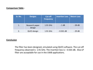
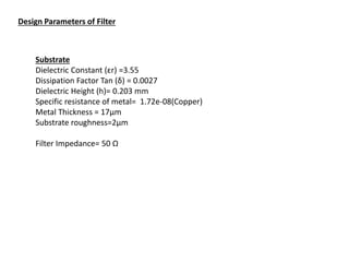
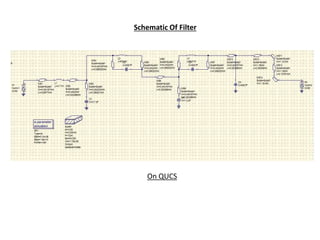
This document summarizes the design, simulation, and testing of a low pass filter for ultra-wideband radar applications. It presents the design parameters of the filter, including the substrate properties and metal thickness. It also shows the schematic of the filter designed in QUCS software. The simulation results show an insertion loss of -0.501 dB and return loss of -29 dB at a cutoff frequency of 1.91 GHz, matching well with the research paper design. The filter meets the requirements for UWB applications.
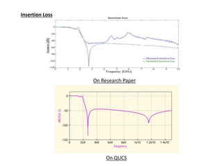
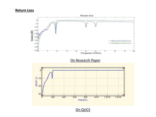
![On Research Paper
On QUCS
Performance
0 2e9 4e9 6e9 8e9 1e10 1.2e10 1.4e10
-150
-100
-50
0
frequency
frequency
dB(S[1,1])
dB(S[2,1])
frequency: 1.91e+09
dB: -3.57
frequency: 1.91e+09
dB: -3.57](https://image.slidesharecdn.com/filterppt-211101203207/85/Filter-ppt-8-320.jpg)