Fike Rupture Disc Sizing Bulletin
•
1 like•1,145 views

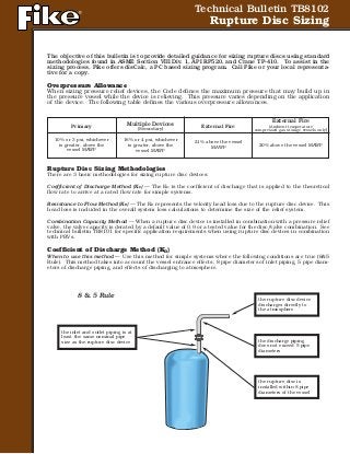
The objective of this bulletin is to provide detailed guidance for sizing rupture discs using standard methodologies found in ASME Section VIII Div. 1, API RP520, and Crane TP-410. To assist in the sizing process, contact Instrument Specialties at 407.324.7800 or visit www.isisales.com.

Recommended
Recommended
More Related Content
More from Instrument Specialties, Inc.
More from Instrument Specialties, Inc. (20)
Recently uploaded
Recently uploaded (20)
Fike Rupture Disc Sizing Bulletin
- 1. Technical Bulletin TB8102 Rupture Disc Sizing The objective of this bulletin is to provide detailed guidance for sizing rupture discs using standard methodologies found in ASME Section VIII Div. 1, API RP520, and Crane TP-410. To assist in the sizing process, Fike offers disCalc, a PC based sizing program. Call Fike or your local representa- tive for a copy. Overpressure Allowance When sizing pressure relief devices, the Code defines the maximum pressure that may build up in the pressure vessel while the device is relieving. This pressure varies depending on the application of the device. The following table defines the various overpressure allowances. Rupture Disc Sizing Methodologies There are 3 basic methodologies for sizing rupture disc devices: Coefficient of Discharge Method (KD) — The KD is the coefficient of discharge that is applied to the theoretical flow rate to arrive at a rated flow rate for simple systems. Resistance to Flow Method (KR) — The KR represents the velocity head loss due to the rupture disc device. This head loss is included in the overall system loss calculations to determine the size of the relief system. Combination Capacity Method — When a rupture disc device is installed in combination with a pressure relief valve, the valve capacity is derated by a default value of 0.9 or a tested value for the disc/valve combination. See technical bulletin TB8101 for specific application requirements when using rupture disc devices in combination with PRVs. Coefficient of Discharge Method (KD) When to use this method — Use this method for simple systems where the following conditions are true (8&5 Rule). This method takes into account the vessel entrance effects, 8 pipe diameters of inlet piping, 5 pipe diam- eters of discharge piping, and effects of discharging to atmosphere. Primary 10% or 3 psi, whichever is greater, above the vessel MAWP Multiple Devices (Secondary) 16% or 4 psi, whichever is greater, above the vessel MAWP External Fire 21% above the vessel MAWP External Fire (Ambient temperature compressed gas storage vessels only) 20% above the vessel MAWP 8 & 5 Rule the inlet and outlet piping is at least the same nominal pipe size as the rupture disc device the rupture disc device discharges directly to the atmosphere the discharge piping does not exceed 5 pipe diameters the rupture disc is installed within 8 pipe diameters of the vessel
- 2. Gas / Vapor Sizing Determination of Critical vs. Subcritical Flow per API RP520 Critical Pressure: If use critical flow equations Calculations per ASME Section VIII (assumes critical flow) Critical Flow: Calculation per API RP520 Subcritical Flow: Critical Flow: W = rated flow capacity, lb/hr V = rated flow capacity, scfm Q = rated flow capacity, US gallons/min A = minimum net flow area, sq. in. C = constant based on the ratio of specific heats k k = cp/cv KD = coefficient of discharge (0.62 for rupture disc devices) KN = correction factor for steam KSH = superheated steam correction factor. For saturated steam use 1.0. Kv = viscosity correction factor F2 = r = Pe P P = set pressure plus overpressure allowance plus atmospheric pressure, psia Pe = exit pressure, psia M = molecular weight SG = specific gravity of gas at standard condi- tions, SG=1.00 for air at 14.7 psia and 60‚°C T = absolute temperature at inlet, R (°F + 460°F) w = specific weight of water at inlet Z = compressibility factor for corresponding to P and T. Use 1.0 if unknown. TABLE 1 Gas Constants Gas or Vapor Molecular k= cp/cv Weight Air Acetic Acid Acetylene Ammonia Argon Benzene N-Butane ISO-Butane Butene Carbon Monoxide Carbon Disulfide Carbon Dioxide Chlorine Cyclohexane Ethane Ethyl Alcohol Ethyl Chloride Ethylene Helium Hydrochloric Acid Hydrogen Hydrogen Sulfide Methane Methyl Alcohol Methyl Chloride Natural Gas (Ave.) Nitric Acid Nitrogen Oxygen Pentane Propane Sulfur Dioxide Water Vapor 28.97 60 26.04 17.03 40 78.1 58.12 58.12 56.1 28 76 44.01 70.9 84.16 30.07 46.07 64.5 28.05 4 36.5 2.016 34.07 16.04 32.04 50.48 19 30 28 32 72.15 44.09 64.06 18.02 1.40 1.15 1.26 1.33 1.67 1.12 1.094 1.094 1.10 1.40 1.21 1.30 1.36 1.09 1.22 1.13 1.19 1.26 1.66 1.41 1.41 1.32 1.31 1.20 1.20 1.27 1.40 1.404 1.40 1.07 1.13 1.29 1.324 k C k C 1.00 315 1.40 356 1.02 318 1.42 358 1.04 320 1.44 360 1.06 322 1.46 361 1.08 325 1.48 363 1.10 327 1.50 365 1.12 329 1.52 366 1.14 331 1.54 368 1.16 333 1.56 369 1.18 335 1.58 371 1.20 337 1.60 373 1.22 339 1.62 374 1.24 341 1.64 376 1.26 343 1.66 377 1.28 345 1.68 379 1.30 347 1.70 380 1.32 349 2.00 400 1.34 351 2.10 406 1.36 352 2.20 412 1.38 354 TABLE 2 Gas Flow Constant C for Sonic Flow 2 k/(k - 1)
- 3. Temperature (°F) Steam Sizing Calculation per ASME Section VIII Steam: Calculation per API RP520 Steam: TABLE 3 Superheated Steam Correction Factors, KSH 300 400 500 600 700 800 900 1000 1100 1200 15 1.00 0.98 0.93 0.88 0.84 0.80 0.77 0.74 0.72 0.70 20 1.00 0.98 0.93 0.88 0.84 0.80 0.77 0.74 0.72 0.70 40 1.00 0.99 0.93 0.88 0.84 0.81 0.77 0.74 0.72 0.70 60 1.00 0.99 0.93 0.88 0.84 0.81 0.77 0.75 0.72 0.70 80 1.00 0.99 .093 0.88 0.84 0.81 0.77 0.75 0.72 0.70 100 1.00 0.99 0.94 0.89 0.84 0.81 0.77 0.75 0.72 0.70 120 1.00 0.99 0.94 0.89 0.84 0.81 0.78 0.75 0.72 0.70 140 1.00 0.99 0.94 0.89 0.85 0.81 0.78 0.75 0.72 0.70 160 1.00 0.99 0.94 0.89 0.85 0.81 0.78 0.75 0.72 0.70 180 1.00 0.99 0.94 0.89 0.85 0.81 0.78 0.75 0.72 0.70 200 1.00 0.99 0.95 0.89 0.85 0.81 0.78 0.75 0.72 0.70 220 1.00 0.99 0.95 0.89 0.85 0.81 0.78 0.75 0.72 0.70 240 - 1.00 0.95 0.90 0.85 0.81 0.78 0.75 0.72 0.70 260 - 1.00 0.95 0.90 0.85 0.81 0.78 0.75 0.72 0.70 280 - 1.00 0.96 0.90 0.85 0.81 0.78 0.75 0.72 0.70 300 - 1.00 0.96 0.90 0.85 0.81 0.78 0.75 0.72 0.70 350 - 1.00 0.96 0.90 0.86 0.82 0.78 0.75 0.72 0.70 400 - 1.00 0.96 0.91 0.86 0.82 0.78 0.75 0.72 0.70 500 - 1.00 0.96 0.92 0.86 0.82 0.78 0.75 0.73 0.70 600 - 1.00 0.97 0.92 0.87 0.82 0.79 0.75 0.73 0.70 800 - - 1.00 0.95 0.88 0.83 0.79 0.76 0.73 0.70 1000 - - 1.00 0.96 0.89 0.84 0.78 0.76 0.73 0.71 1250 - - 1.00 0.97 0.91 0.85 0.80 0.77 0.74 0.71 1500 - - - 1.00 0.93 0.86 0.81 0.77 0.74 0.71 1750 - - - 1.00 0.94 0.86 0.81 0.77 0.73 0.70 2000 - - - 1.00 0.95 0.86 0.80 0.76 0.72 0.69 2500 - - - 1.00 0.95 0.85 0.78 0.73 0.69 0.66 3000 - - - - 1.00 0.82 0.74 0.69 0.65 0.62 Burst Pressure (psig) 3
- 4. 4 Resistance to Flow Method (KR) When to use this method — Use this method when the 8&5 Rule does not apply. When the disc is installed in combination with a pressure relief valve, this method can be used to calculate the pressure drop between the pres- sure vessel and the valve. Rupture disc devices can be characterized as to their respective resistance to fluid flow. The KR value represents the velocity head loss due to the rupture disc device. This head loss is included in the overall system loss calcu- lations to determine the capacity of the relief system. ASME PTC25 provides standardized test methods to measure the KR of rupture disc devices. By quantifying this performance characteristic, rupture disc devices may be accounted for in piping system sizing calculations in the same way as piping and piping components (exit nozzles on vessels, elbows, tees, reducers, valves). NOTE: It is important to understand that the certified KR is representative of the device (disc and holder), not simply the rupture disc. In cases where there is no holder, the KR value is for the disc, which is then defined as the device. The following examples will illustrate how KR values are used to establish the flow capacity of a pressure relief pip- ing system. Vapor Sizing The following example, see Figure 1, assumes that k = Cp/Cv = 1.4 which results in a conservative calculation. The example shown is based on Crane TP-410 methods. It also assumes a steady state relieving condition where the vessel volume is large relative to the relieving capacity. Given information: 1. Pressure vessel MAWP = 1000 psig. 2. Relieving pressure as allowed by ASME Section VIII Div.1 = 110% x MAWP = 1114.7 psia = P'1 3. Back pressure (outlet pressure) = 14.7 psia = P2 4. Working fluid - air (k = Cp/Cv = 1.4) 5. Air temperature at disc rupture = 500°F = 960°R = T1 6. Maximum flow rate into the vessel = 20,000 SCFM-Air 7. Rupture Disc - FIKE 3" SRX-GI ➜ KR = 0.99 Liquid Sizing Calculation per ASME Section VIII Water: Calculation per API RP520 Non-viscous liquid: Viscous liquid: AV = For viscous liquid sizing, first calculate AR using Kv of 1.0 Apply the area A of the next larger size disc to the Reynolds number calculations to arrive at Kv. Then re-calculate required area AV using the derived Kv. (u is in centipoise) (U is in Saybolt Universal Seconds, SSU) Elbow (K4) 20' of 3" 10 PIPE (K3) PRESSURE VESSEL MAWP = 500 PSIG FIKE 3" SRX GI HOLDER (KR) 1' of 3" ID PIPE (K2) ENTRANCE EFFECT (K1) EXIT EFFECT (K6) Figure 1. 40' of 3" ID PIPE (K5) AR AR Kv AR = Required Area without viscosity corrections (sq. in.) AV = Required Area with viscosity correction (sq. in.)
- 5. 5 Piping Component Flow Resistance Value Reference Or Feature (K) Entrance - Sharp Edged K1 = 0.50 Crane 410 Pg A-29 1 ft. of 3" Sch. 40 Pipe K2 = 0.07 K=fL/D; f = .018 (Crane 410 Pg A-26) L = 1 ft, ID = 3.068/12 ft FIKE 3" SRX-GI Rupture Disc KR = 0.99 National Board Cert. No. FIK-M80042 20 ft. of 3" Sch. 40 Pipe K3 = 1.41 K=fL/D; f = .018 (Crane 410 Pg A-26) L = 20 ft, ID = 3.068/12 ft 3" Sch. 40 Standard 90° Elbow K4 = 0.54 Crane 410 Pg A-29 40 ft. of 3" Sch. 40 Pipe K5 = 2.82 K=fL/D; f = .018 (Crane 410 Pg A-26) L = 40 ft, ID = 3.068/12 ft Pipe exit - Sharp Edged K6 = 1.00 Crane 410 Pg A-29 Total System Flow Resistance KT = 7.33 KT = K1 + K2 + KR + K3 + K4 + K5 + K6 The Darcy Equation defines the discharge of com- pressible fluids through valves, fittings and pipes. Since the flow rate into the example vessel is defined in SCFM, the following form of the Darcy equation is used: Crane Equation 3-20 Determine the Total Piping System Resistance Factor: To determine Y, first it must be determined if the flow will be sonic or subsonic. This is determined by com- paring the actual ∆P/ P'1 to the limiting ∆P/ P'1 for sonic flow. Crane Table A-22 shows limiting factors for k=1.4 for sonic flow at a known value of KT. If (∆P/ P'1)sonic < (∆P/ P'1)actual, then the flow will be sonic. Limiting Factors for Sonic Velocity (k = 1.4) Excerpted from Crane 410 Pg A-22 K P/ P'1 Y 1.2 .552 .588 1.5 .576 .606 2.0 .612 .622 3 .622 .639 4 .697 .649 6 .737 .671 8 .762 .685 10 .784 .695 15 .818 .702 20 .839 .710 40 .883 .710 100 .926 .710 ∇ q'm = rate of flow in cubic feet per minute at standard conditions (14.7 psia and 60°F) Y = net expansion factor for compressible flow through orifices, nozzles and pipes (Crane 410 Pg A-22) d = internal diameter of pipe (in.) ∆P = Change in pressure from state 1 to 2 (entrance to exit). P'1 = Pressure at state 1 (entrance) = psia K = Loss coefficient T1 = Absolute temperature at state 1 (entrance) in degrees Rankine (°R) Sg = Specific gravity relative to air = 1.0 (for this example)
- 6. 6 For this example: From table A-22 at KT =7.33 = 0.754 Since (∆P/ P'1)sonic < (∆P/ P'1)actual, the flow is sonic in the piping. Thus, we will use Ysonic = 0.680 in the flow cal- culations (Crane 410 Eq. 3-20.) Since (∆P/ P'1)sonic = .762, then ∆P = 0.754* P’1 = 0.754*1114.7 = 840.5 psi Calculating the system capacity is completed by substituting the known values into Crane 410 Equation 3-20. The ASME Pressure Vessel Code, Section VIII, Division 1, paragraph UG-127(a)(2)(b), also requires that the calcu- lated system capacity using the resistance to flow method must also be multiplied by a factor of 0.90 or less to account for uncertainties inherent with this method. Thus, the system capacity is greater than the required process capacity (20,000 SCFM Air) Subsonic Flow Case In the case where the flow subsonic, or (∆P/ P'1)sonic < (∆P/ P'1)actual, simply read the value of Yactual from Crane 410 chart A-22, Substitute (∆P/ P'1)actual and Yactual into the calculations. Liquid Sizing For this example Figure 2 is assumed, water will be considered the flow media. The example shown is based on Crane TP-410 methods. It also assumes a steady state relieving condition where the vessel volume is large rela- tive to the relieving capacity. Given information: 1. Pressure vessel MAWP = 500 psig. 2. Relieving pressure as allowed by ASME Section VIII Div. 1 = 110% x MAWP = 550 psig = P1 3. Back pressure (outlet pressure) = 0 psig = P2 4. Working fluid - Water 5. Temperature = 70°F 6. Maximum flow rate into the vessel = 50 ft3 /min 7. Rupture Disc - FIKE 2" SRX-GI ➜ KR = 0.38 From Crane 410: “Bernoulli’s Theorem is a means of expressing the application of the law of conservation of energy to the flow of fluids in a conduit [piping]. The total energy at any particular point, above some arbitrary hori- zontal datum plane, is equal to the sum of the ele- vation head [“Z”], the pressure head [“P”], the veloc- ity head [“V”].” In real applications, there are energy losses in piping systems between states (or location) 1 and 2. Those losses are accounted for in the term hl, which are predominantly frictional head losses. The energy balance is then expressed Crane Equation 1-3 ∆ Figure 2. Where: Z1 and Z2 = elevation head at states 1 and 2 (ft. - “feet”) P1 and P2 = pressure at states 1 and 2 (psig) V1 and V2 = velocity at states 1 and 2 (ft/sec) ρ1 and ρ1 = fluid density at states 1 and 2 (lb/ft3 ) g = acceleration due to gravity (32.2 ft sec2 ) hl = frictional head loss (ft.) 840.5 * 1114.7 7.33 * 960 *1 50,074*0.90 = 45,066 SCFM – Air 678*0.680*(3.068)2 50,074SCFM – Air 40' of 2" PIPEElbow 20' of 2" PIPE PRESSURE VESSEL MAWP = 500 PSIG FIKE 2" SRL GI HOLDER 1' of 2" PIPE ENTRANCE EFFECT EXIT EFFECT
- 7. Thus, Other known conditions: Vvessel = 0 ft/sec Zvessel = 0 ft Zexit ~ 1 ft + 20 ft = 21 ft = elevation change of piping Pexit = 0 psig ρ1 = ρ2 = 62.3 lb/ft3 for water at room temperature Substituting values into Equation 1-3, Solving for V2 (exit velocity), The friction factor used earlier in the calculations for piping frictional losses assumed that the flow in the pipes was fully turbulent flow. The value of the friction factor is related to the Reynolds Number (Re) of the resulting flow (Ref: Crane 410 pg 1-1). For Re < 2000, the flow is laminar and the friction factor is a function of Reynolds Number, only. For Re > 4000, the flow is fully turbulent and the friction factor is also a function of the character of the piping wall (relative roughness). 7 As in the previous example, head losses due to friction in the piping and the head losses due to fittings are pro- portional to the sum of the flow resistances: Since the actual head loss is velocity dependent, Frictional loss coefficients and fitting loss coefficients for the example are as follows: Piping Component Flow Resistance Value Reference Or Feature (K) Piping Frictional Losses 1 ft. of 2" Sch. 40 Pipe K1' pipe = 0.11 K=fL/D; f = .019 (Crane 410 Pg A-26) L = 1 ft, ID = 2.067/12 ft 20 ft. of 2" Sch. 40 Pipe K20' pipe = 2.21 K=fL/D; f = .019 (Crane 410 Pg A-26) L = 20 ft, ID = 2.067/12 ft 40 ft. of 2" Sch. 40 Pipe K40' pipe = 4.41 K=fL/D; f = .019 (Crane 410 Pg A-26) L = 40 ft, ID = 2.067/12 ft Fitting Losses Entrance - r/d = 0.10 Kent = 0.09 Crane 410 Pg A-29 FIKE 2" SRL-GI Rupture Disc KR = 0.38 National Board Cert. No. FIK-M80031 2" Sch. 40 Standard 90° Elbow Kel = 0.57 Crane 410 Pg A-29 Pipe exit - Sharp Edged Kexit = 1.00 Crane 410 Pg A-29 Total Losses KT = 8.77
- 8. Now that the fluid velocity is known, the volumetric flow rate can be calculated. Where Substituting values, Per the ASME Code, the rated system capacity is, Therefore, the relief system can flow the required 50 ft3 /min. The friction factor used earlier must be verified. First calculate the Reynolds Number: V = fluid velocity = 90.78 ft/sec d = pipe diameter = 2.067in/12 in/ft ν = kinematic viscosity = 0.000011 ft2 /sec Since the Reynolds Number is >>4000, the flow is turbulent, and the friction factor is now a function of the relative roughness of the pipe. From Crane 410 Figure A-23, the friction factor, f, for 2" commercial steel pipe in fully turbulent flow is 0.019. This verifies the original assumption for friction factor. 704 South 10th Street • Blue Springs, Missouri 64015-4263 U.S.A. (816) 229-3405 • Telefax (816) 228-9277 Home Page: http//www.fike.com • e-mail: fmpsales@fike.com February, 2000 Revised Issue FORM NO. TB8102-5 200 Copyright © 2000 by Fike Corporation All rights reserved Printed in U.S.A. ® Laminar Flow Considerations If the flow had been laminar, Re < 2000, the friction factor is calculated as: f = 64/Re If this friction factor had not been close to the same value used to determine frictional loss coefficients used earlier, the calculation must be repeated and iteratively solved until the assumed friction factor equals the calculated friction factor. References: American Society of Mechanical Engineers, Boiler and Pressure Vessel Code Section VIII, Division 1, 1998 Edition American Socity of Mechanical Engineers, PTC25 American Petroleum Institute, RP520 Crane Valves, Technical Paper 410 Crane Valves, Crane Companion Computer Program Fike Technical Bulletin TB8104 Certified KR Factors π