This paper presents a new multi-objective optimization algorithm for solving economic load dispatch problems in power systems. The algorithm uses linear programming techniques to minimize total generation cost while meeting constraints like line flows, voltage limits, and emission levels. It models both real and reactive power optimization problems and can handle emergency situations like transmission line outages. The algorithm is tested on two power system examples and shown to obtain optimal solutions balancing objectives such as economy, reliability and environmental impact.

 (2)
9s 9s 9s 9s 9s 9s
then
AJ=blAP tP1 [cNP ,APT [c]P +APT [c]AP
9s 9s 9s gs 9s gs 9s
= (bTt2PT [c])AP +APT [c]AP (3)
9s 9s 9s 9s
As the value of P approach to the optimal point, AP
9s 9s
becomes so small that we can neglect the term of (AP )2.9s
1hen we have the new objective function
(4)
gs
AJ = boTAP
where
bIT = bT t 2P:s [c]
= (bl b2 ...bk ...b
, 1 * I
n )
9s
with bk = bk t 2c P
k 9k
1he control variables AP . must obey:
91
Pm -Po. < A P .< P M - P o
g1 gi - gi - gi gi
(5)
where
P:i
P:
P:
is the initial value of real power generated at
generating bus i
is the upper limit of real power generated at
generating bus i
is the lower limit of real power generated at
generating bus i
Since some of the APgi may be negative and linear
programming can only operate on nonnegative variables, new
variables should be introduced through i
Xgi 4AP .t P:i - P z (6)
91
so that the conditions of Eqn. 5 reduce to:
(-1)
Then we can express the original variables AP with
gi
respect to the new variables X as follows:
9i
AP . X - Po. t Pm (8)
gi gi gi gi
Substituting of Eqn. 8 into Eqn. 4. we have
=b'(Xgs -Po9s + Pm)9sAJ
= b' X t b' ( -Po t Pm ) (9)
9s 9s 9s
Since the constant terms of the objective function to be
extremized are insignificant, we can use the following
objective function
" ,
gs k=l k gk
A J = d X = C g S b X
which is a linear function with respect to the new variables
'gi.
CONSTRAINTS
The Newton-Raphson method formulates a set of linear
equations expressing the real and reactive power injection
errors at buses as follows:
ap apwhere, H. N. 3. L are Jacobian matrices defined as s,3~
,2and %respectively (4-7).
In the real power optimization procedure, setting AV =
0 firstly. l h e relationships of AP, AQ with Ae can be
expressedby the following equations (3-5):
AP = [ H l A Q
AQ = [ J ] A e
(i)Real Power Balance Condition
The real power balance condition is defined as the
Equality Constraints. l h e slack bus real power balance
condition can be written similar to Eqn. (12(a)) as follows:
APs = [ H ] A0 (13)
From Eqn. (12(a)), we have
P n 1
where H is the inverse of the Jacobian matrix H (3-7).
)xq, )-$,l-$are matrices consisting of the column vectors of
the matrix H pertaining to generation buses, control buses,
and load buses, respectively.
Since the bus power of the non-generator buses cannot
be changed, i.e. APc = 0 and Apt= 0. Equation (14) can be
written as follows:
A@= [H,l AP9 (15)
(16)
Substituting Eqn. (15) into Lqn. (13) leads to:
aPs = CHsl[H 1AP
APgi= X91.- Po.91 t Pm91
9 9
Using equation (8)](https://image.slidesharecdn.com/farag1995-190728070907/85/Farag1995-2-320.jpg)
![733
and substituting in Eqn. (16) in view of Eqn. (8). then
xgs - P O t P; = [lis] [Hgl(Xg - Pgot P$
9s
or exoressed in the form
(ii) Line Overload Prevention Condition
l h e line overload prevetion condition is defined as the
Inequality Constraint (4.5). The overloading in a transmission
line can lead to system collapse in an extreme case. The
following condition must be satisfied for preventing the line
overload; as a security constraint or security index:
n
1=1
Z AP ( UQ
Q ..? kei gi
where
ZQ
UQ
and KQi
is the line flow through line Q
is the upper limit of transmission power of line Q
is the sensitivity between line flow of line Q and
power injection of bus i (i.e. AZQ/APi)
Substituting from Eqn. (8) for AP in Eqn. (18), we get:
9i
n
m
Q i=l gi gi gi
2 t ? KQi(X - P" t P . ) (UQ
or
n n
l h e problem size can be reduced by taking into
consideration only the constraints of the lines whose loading
is approaching their maximum rating IJQ. It can be taken as
90% of normal loading (6.7).
( 5 ) Upper/Lower Bounds on Each Generator Output Power:
Rewriting Eqn. (17) in a compact form leads to:
O I X t P - P " (20)
p - 9 9
1he Simplex Method with Bounded variables handles
these constraints on the control variables implicitly without
increasing the problem size.
(iv) Environmental Impact (91:
Generation emission can be taken as an index for
environment conservation. The following condition must be
satisf ied:
C-P-.
2 G
a t f 3 P t y P t Eexp V
G G
where a, 0. y. 5. E are coefficient of generator
emission characteristic and V is the allowable upper limit.
2. _OPTIMUMSCHEDULING OF REACTIVE GENERATION
The gbiective function of the optimum scheduling of the
reactive generation is obtained as follows:
Setting A 0 = 0 in Eqn. (I I), the changes in the active
power and reactive power caused by the bus voltage change
can be expressed as follows:
AP = [Ngs] AV
AQ = [t.] AV (21)
where:
[N ] is the (n x n ) matrix consisting of the row
of the Jacobian matrix [NI pertaining to the
generator buses.
9s 9s b
Substituting Eqn. (21) for AP9s into Eqn. (4) leads to
A3 = blT [Ngs]AV
0 "
where: bnT
1he control variable AVi must satisfy the following
b'l (NqJ = (b ,b2, .b i d .
conditions:
(23)
M
V y ( V p tAVi<Vi
Thus, by introducing the new nonnegative variables Xvi. Eqn.
(23) is reduced to:
0 < X v i ( v y -vm (24)
where:
Xvi AVi t V p - Vm. (25)
and AVi = Xvi - Vy + V m
Substituting Eqn. (25) into Eqn. (22) and eliminating
the constant terms, the linear objective function , with
respect to, the new variable is obtained as:
AJ = b Xv
CONSTRAINTS
(i) Conditions on Reactive Power
Separating the Eqn. (21) into two parts, one pertaining to
the voltage-controlled buses and the other pertaining to the
load buses, we get:
AQgc
(27)
where [AQQ 1 = [::I -AV
[Lgc]and[LQ] are the matrices consisting of the
rows of the matrix [L] pertaining to
the voltage-controlled buses and the
load buses respectively.
For the voltage-controlled buses, the reactive power
must be inside the permissible range given by:
Qg"c 5 Qic + AQgc -< QMgc (28)
For the load buses, the reactive power cannot be changed: i.e.
Substituting Eqn. (27) into Eqns. (28). (29) leads to
AQQ= 0 (29)
Qic + [Lgcl AV 5 Q E
QZc t EL9c1 AV5Q;
['-a] AV = O
or in the form of Eqn. (25) as follows:](https://image.slidesharecdn.com/farag1995-190728070907/85/Farag1995-3-320.jpg)
![734
(ii)Upper and Lower Bounds on Each Bus Voltaqe:
Rewriting Eqn. (24)in a compact form such as:
O < X v 5 V M - V m (32)
which can be implicitly treated without increasing the
problem size.
3. CONTINGENCY ANALYSIS
When it is impossible to dispatch the load without
overloading the lines, the solution of the linear programming
problem in the real power optimization procedure appears to
be infeasible. In such cases, the solution can be feasible by
assuming the possibility of load shedding. In this case, the
objective function is written as the sum of the following two
terms: the first is the objective function in the real power
optimization procedure, i.e. Eqn. (IO) and the second is a
weighted sum of load shedding quantities given as:
n n
1
3 = ? b' X t E (WF). X (33)
k = l k gk j=l 1 Qj
where:
XQj= APQj is the variable representing the load
shedding quantity APQj of the load bus j.
which is nonnegative and needs not be
replaced, and
is the weighting factor assigned to reflect
the load priority of load bus j. which must
be made greater than the largest values of
9s'
b' for k = 1. 2. ......n
(wF)j
CONSTRAINTS
(i)Real Power Balance Condition:
Since the power change quantity of a bus equals to
the sum of the power generation change and the load change.
we can write
AP =APc t A P L (34)
APS = APcs t APLs (35)
In analogy with Eqns. (16). (17). it is possible to
rewrite:
APcs + APLc = [HSI [HI(APc t APL)
or in view of Eqn. (8) and the definition of XQfAP L,
XCs - PEs t P& iXQs= [HS][HI(Xc - PE + P; t X $; or
(36)
Etis] EH1(xC XQ) - xGS - xQS
(37)
(ii) Line Overload Prevention Condition
In the same manner as in the case of real power
optimization, we get:
n n
b o m b
Z + E K (X E K X < U ,or
Q i=lQ i Gi -'Ci) j=l Qj Qj- Q
n n n
b b b o m
i = l QiCi j=1 QJ QJ Q Q i = l QiCi Ci
E K .X . t . E K .X . < U - Z t E K (P - P )
(iii) Bounds on Xci and XLi
The bounds on XGi and Xei can be presented as:
0 5 xci 5 Pzi- Pgi
0 5 xu 5 x;
where
X; is the upper limit of load shedding quantity
AP,-i at bus i.
SECTION REDUCTION METHOD
At the first iteration, the temporary section of each
control variable is set to be the part of the original range
within the distance of AD from the initial point of the
control variable, where D denotes the width of the original
range between upper and lower limits of the control variable.
The value A is determined according to the estimated
maximum distance between the initial points and the optimal
points (0.1 </ h 5 1.0).
As the iteration is repeated, the temporary section of
the next iteration is reduced to k times as wide as that of the
previous iteration.
In general, it is reasonable to choose k as 0.5. but may be
somewhat adjusted in accordance with the circumstances.
The constant k is called the Section Reduction Factor.
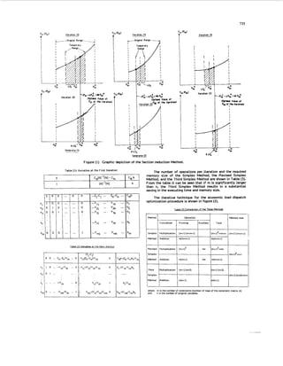
The procedure for extremizing the problem of n
generators is depicted in Figure (1).
THIRD SIMPLEX METHOD AND SOLUTION PROCEDURE
It is possible to develop the modified simplex method by
reconstructing an identity matrix from the tables at every
iteration by extracting the unit vectors and rearranging
them. By using this developed method, the execution time
and memory size are substantially reduced as a unit vector is
generated at every iteration instead of the identity matrix.
In general, the linear programming problem is written as
follows.
Minimize
Subject to
where:
A =
B =
x =
b
N
B. N
J CZ
[A] X 2 b with X >_ 0
[B N] is the constraint matrix.
(C. C) is the Cost Coefficient Vector,
(X. X) is the variable vector,
is the basic matrix,
is the non-basic matrix, and
are the underscripts pertaining to basic and
non-basic variables respectively.
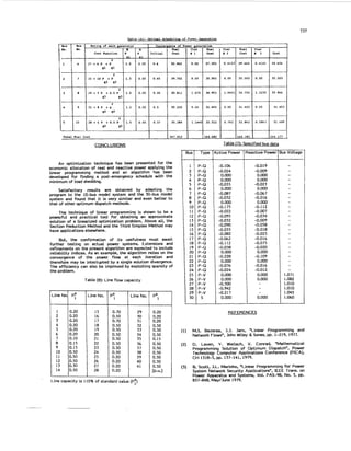
At the initialization step, the slack and surplus variables,
and the artificial variable are introduced as shown in Table
(1).
A t the main step, the leaving and entering variables are
determined. and, after the pivoting operation is carried out,
Table (2)is obtained.
Comparing Tables (1) and (2). it is observed that the unit
vector of the r-th column has been transferred to the k-th
column. 1P we exchange the unit vector of the k-th column
for the new r-th column vector, we obtain the same result by
operating with only the right side part of the matrix [ 1 B- 1
N I.](https://image.slidesharecdn.com/farag1995-190728070907/85/Farag1995-4-320.jpg)
![736
-ine
lumber
1
2
3
4
5
6
7
8
9
10
11
12
13
Table (5): Bus voltage and Connected Load
Bus
Number
1-2
1-6
1-9
2-3
2-6
3-7
4-7
4-8
5-6
5-10
6-9
8-10
9-10
Set Initial Conditions of
P,, and VI
Perform the Real Power Optimization Algorithm
and Update Poi to PZ+AP$
1----
1
S o h the Power Flow of the System on the
Update Values of Pi
Calculate b”, [NI. [L]
II Solve the Power Flow of the System on the
Update Valuer of Vi
-
Bus
No.
-1
2
3
4
5
6
7
8
9
10
.-
voltage at
(Per unit) Iteration
2 Not specified 0.2
2 Not specified 0.3
2 Not specified 0.2
2 Not specified 0.3
2 Not specified 0.2
3 I.o 0.3
3 1.o 0.15
3 I.o 0.2
3 1.o 0.2
1 1.05 0.2
+ j0.097
+ j0.145
+ j0.097
+ j0.145
+ j0.097
+ j0.145
+ j0.0726
+ j0.097
+ j0.097
+ j0.097
I
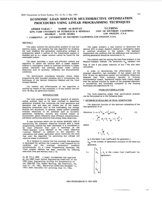
Figure (2): Iterative Procedure
RESULTS ON EXAMPLE (1) SYSTEM STUDIES
A IO-bus model system shown in Figure (3) was used to
test the method of scheduling real and reactive power and to
study the convergence characteristics of the optimization
process prsented in the paper.
The impedance and line charging data is given in Table
(4)and the bus voltage and load data are given in Table (5).
The operating limits and cost data for each generator and
real power generations of each iteration are shown in Table
(6). In consequence of continuing the iteration procedure until
the cost flucturation AC becomes smaller than 0.05% of
cost, the number of load flow calculation is 3 times.
Table (4):Line Impedance and Charging Susceptance
Line
Impedance
0.02 + j0.08
0.06 + j0.24
0.04 + j0.16
0.06 + j0.24
0.06 + j0.24
0.06 + j0.24
0.04 + jO.16
0.06 + j0.24
0.04 + j0.16
0.06 + j0.24
0.01 + j0.04
0.04 + j0.16
0.08 + j0.32
Line charging
susceptance
0.03
0.02
0.015
0.02
0.02
0.02
0.015
0.02
0.015
0.02
0.01
0.015
0.025
0.9737
0.9650
0.9726
0.9996
1.0123
0.9875
1.0125
0.9882
1.0175
Figure (3): 10Bus Model System
RESULTS ON EXAMPLE (2)SYSTEM STUDIES
The proposed optimization algorithm is applied to the
IEEE 30 Bus test system with 6 generators and 41 lines given
in Fig. (4). The system data are given in Tables (7)and (8).as
obtained for Reference (9). The results using new algorithm
are shown in Tables (9)and (IO) for the optimal solution of
the subproblem as compared to Table (1 I) of Reference (9).
The numerical results on this power system have verified the
validity of the algorithm with respect to the existing oms.
The memory size and execution time using the Third Simplex
Method has been reduced tremendously.
Fig. (4):30 Bus Test System 191](https://image.slidesharecdn.com/farag1995-190728070907/85/Farag1995-6-320.jpg)