1. AIR COIL INDUCTORS
SINGLE LAYER AIR COIL WINDING FORMULA AND Q FACTOR
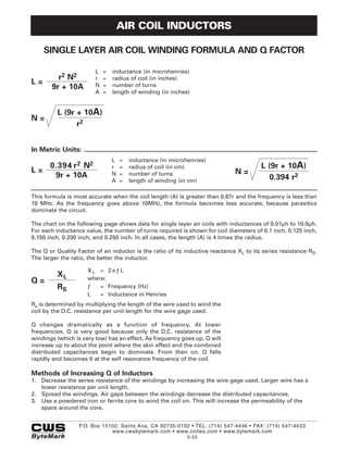
L = inductance (in microhenries)
r2 N2 r = radius of coil (in inches)
L= N = number of turns
9r + 10A
A = length of winding (in inches)
L (9r + 10A)
N=
r2
In Metric Units:
L = inductance (in microhenries)
0.394 r 2 N2 r = radius of coil (in cm) L (9r + 10A)
L= N = number of turns N=
9r + 10A 0.394 r2
A = length of winding (in cm)
This formula is most accurate when the coil length (A) is greater than 0.67r and the frequency is less than
10 MHz. As the frequency goes above 10MHz, the formula becomes less accurate, because parasitics
dominate the circuit.
The chart on the following page shows data for single layer air coils with inductances of 0.01µh to 10.0µh.
For each inductance value, the number of turns required is shown for coil diameters of 0.1 inch, 0.125 inch,
0.150 inch, 0.200 inch, and 0.250 inch. In all cases, the length (A) is 4 times the radius.
The Q or Quality Factor of an inductor is the ratio of its inductive reactance XL to its series resistance RS.
The larger the ratio, the better the inductor.
XL = 2πƒL
XL where:
Q=
RS ƒ = Frequency (Hz)
L = Inductance in Henries
Rs is determined by multiplying the length of the wire used to wind the
coil by the D.C. resistance per unit length for the wire gage used.
Q changes dramatically as a function of frequency. At lower
frequencies, Q is very good because only the D.C. resistance of the
windings (which is very low) has an effect. As frequency goes up, Q will
increase up to about the point where the skin effect and the combined
distributed capacitances begin to dominate. From then on, Q falls
rapidly and becomes 0 at the self resonance frequency of the coil.
Methods of Increasing Q of Inductors
1. Decrease the series resistance of the windings by increasing the wire gage used. Larger wire has a
lower resistance per unit length.
2. Spread the windings. Air gaps between the windings decrease the distributed capacitances.
3. Use a powdered iron or ferrite core to wind the coil on. This will increase the permeability of the
space around the core.
P.O. Box 15102, Santa Ana, CA 92735-0102 • TEL: (714) 547-4446 • FAX: (714) 547-4433
www.cwsbytemark.com • www.coilws.com • www.bytemark.com
5-33