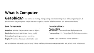
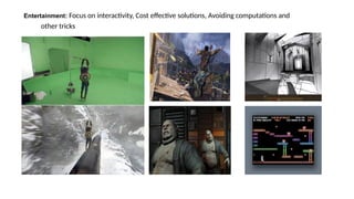
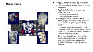
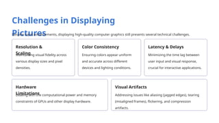
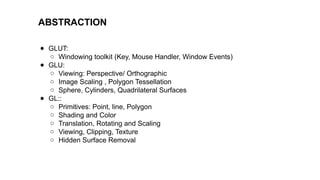
Computer Graphics is the field of study and technology that deals with creating, manipulating, and displaying visual images using computers. It involves generating images ranging from simple 2D drawings to complex 3D models and animations. Applications of computer graphics include video games, simulations, virtual reality, graphic design, movies, and user interfaces. Gaming refers to the creation, design, and playing of video games—interactive digital entertainment that involves players controlling characters or environments to achieve specific goals. It combines storytelling, graphics, sound, and user interaction to deliver engaging experiences across various platforms like consoles, PCs, and mobile devices. Gaming also includes competitive esports and social gaming communities.


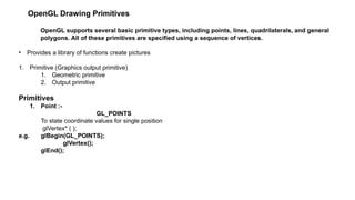
![• Coordinate position can be 2,3 or 4 dimensions
• In 4 dimension the fourth dimension is scaling factor
• Dimensions are specified by first suffix
– e.g. glVertex2
glVertex3
• Second suffix code is used to specify data type
1. i (integer)
2. s (short)
3. f (float)
4. d (double)
e.g. glBegin(GL_POINTS);
glVertex2i(50,100);
glVertex2i(75,150);
glVertex2i(100, 200);
glEnd();
• We can specify the coordinate values using array
• 3rd
suffix code for array is v (vertex)
e.g. float point1 [ ]={50.89,100.60,45.89};
float point2 [ ]={-75.66,150.33,188.77};
float point3 [ ]={100.46,200.15,78.78};
glBegin(GL_POINTS);
glVertex3fv(point1);
glVertex3fv(point2);
glVertex3fv(point3);
glEnd();
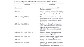
The following code fragment illustrates an example of how the
primitive type is specified and how the sequence of vertices are
passed to OpenGL. It assumes that a window has already been
opened
and that an appropriate 2D coordinate system has already been
established.
// draw several isolated points
GLfloat pt[2] = {3.0, 4.0};
glBegin(GL_POINTS);
glVertex2f(1.0, 2.0); // x=1, y=2
glVertex2f(2.0, 3.0); // x=2, y=3
glVertex2fv(pt); // x=3, y=4
glVertex2i(4,5); // x=4, y=5
glEnd();](https://image.slidesharecdn.com/exploring-the-world-of-computer-graphicsunit12-250916111428-43e3a15c/85/Exploring-the-World-of-Computer-Graphics_unit_1-2-pptx-35-320.jpg)