
Recommended
Recommended
More Related Content
What's hot
What's hot (20)
Similar to Evaluation of seismic fragility of infilled reinforced concrete frames subject to aftershocks
Similar to Evaluation of seismic fragility of infilled reinforced concrete frames subject to aftershocks (20)
More from openseesdays
More from openseesdays (20)
Recently uploaded
Recently uploaded (20)
Evaluation of seismic fragility of infilled reinforced concrete frames subject to aftershocks
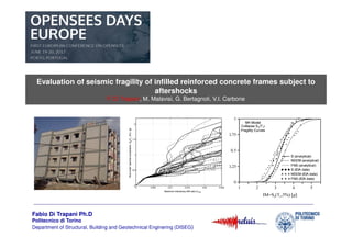
- 1. Fabio Di Trapani Ph.D Politecnico di Torino Department of Structural, Building and Geotechnical Enginering (DISEG) Evaluation of seismic fragility of infilled reinforced concrete frames subject to aftershocks F. Di Trapani, M. Malavisi, G. Bertagnoli, V.I. Carbone Evaluation of seismic fragility of infilled reinforced concrete frames subject to aftershocks F. Di Trapani, M. Malavisi, G. Bertagnoli, V.I. Carbone
- 2. GLOBAL INTERACTION EFFECTS • Modification of overall capacity • Modification of collapse mechanisms • Modification of dynamic properties LOCAL INTERACTION EFFECTS • Local modification of internal forces in RC members • Local shear failure of column ends end joints • Activation of short column mechanisms • Out of plane failure Outline FRAME – INFILL INTERACTION
- 3. Increase of stiffness and bearing capacity Planar regular distribution Regular Distribution over the height Outline GLOBAL FRAME – INFILL INTERACTION EFFECTS (POSITIVE CONTRIBUTION OF INFILLS)
- 4. Outline GLOBAL FRAME – INFILL INTERACTION EFFECTS (Global collapse)
- 5. NEED FOR SEISMIC FRAGILITY ASSESSMENT OF INFILLED FRAMES FRAMES Case of intact structures To assess seismic performance of new and existing buildings To design and compare eventual retrofitting interventions Case of structures damaged from earthquakes To assess if infill walls contribute to a residual capacity against a sequence of earthquakes Bare Infilled Bare Infilled Fragility to mainshocks Fragility to Mainshock+Aftershock
- 6. FRAGILITY ASSESSMENT FRAMEWORK FOR INTACT AND DAMAGED INFILLED FRAME STRUCTURES
- 7. FRAGILITY ASSESSMENT FRAMEWORK Ground motion selection (30 at least records) Evaluation of LS on IDA curves Perform IDAs LS distribution IM 0 1 SL1 IM DM − Φ=≥ X X SL X DMDMP ln lnln )( σ µ Evaluation of Fragility curves of LS Actual CD
- 8. DEFINITION OF INPUTS -3 -2 -1 0 1 2 0 10 20 30 40 50 60 acceleration[g] Time (sec) MAINSHOCK AFTERSHOCK Scaling in Amplitude Scaling in Amplitude Fixed IDA OF INTACT STRUCTURES IDA OF PRE-DAMAGED STRUCTURES IDA OF INTACT STRUCTURES IDA OF PRE-DAMAGED STRUCTURES
- 9. AfterShock IDA FIXED Mainshock IDAs OF MAINSHOCK / AFTERSHOCK SIGNALS
- 10. MODELLING OF INFILLED FRAMES (Concrete 02 Models) FB Nonlinear beam/column Truss Stress fmd0 fmdu εεεεmdu εεεεmd0 Width (w) d c l h kw β γ λ* = w t (actual thickness) += ' ' 2' 2'' * 4 1 h l A A l h A th E E b c cc md λ Asteris et al. (2015) Papia et al. (2003) Fiber section Stress-strain parameters fmd0 εεεεmd0 fmdu εεεεmdu Di Trapani et al. (2017)
- 11. DEFINITION OF COLLAPSE LIMIT STATES Shear distribution coefficients (Cavaleri & D Trapani 2015) 0 0.1 0.2 0.3 0.4 0.5 0.6 0.7 0.8 0.9 1 1.1 1.2 αCNO 0 2 4 6 81 3 5 7 ψ CNO Section 0 2 4 6 81 3 5 7 ψ 0 0.1 0.2 0.3 0.4 0.5 0.6 0.7 0.8 0.9 1 1.1 1.2 αCSE l/h=2 1.08ψ-0.30 l/h=1 1.03ψ-0.35 0.96ψ-0.37 1.05ψ-0.36 CSE Section dr=0.6% dr=0.6% l/h=2 l/h=1 VCNO VCSE VCSE=ααααCSEN VCNO=ααααCNON m0vfξλψ * = SHEAR FAILURE OF COLUMNS ULTIMATE CHORD ROTATION OF COLUMS N(ΘΘΘΘ)/Nmax Θ/ΘΘ/ΘΘ/ΘΘ/Θflex 0 1 1 Axial force- ultimate chord rotation domains
- 12. DEFINITION OF IM and DM Selection of IM PGA Se(T1) PGA or Se(T1) ????? ΘΘΘΘ Selection of DM Maximum drift at the first interstorey Se(T1) cannot be used to compare bare and infilled frames and intact and damaged structures PGA is preferable to compare fragility curves of structures having substantially different proper frequencies
- 13. CASE STUDY
- 14. CASE STUDYCASE STUDY Pinto et al. (2005) ICONS Project
- 15. REFERENCE MODELS
- 16. Equivalent strut model (Di Trapani et al. 2017) Frame elements Modelling in OpenSees
- 17. 30 Spectrum-compatible artificial accelerograms Site: L’Aquila (Italy) Return Period: 1950 years Scaling factors to 15 PGA levels Ground Motion Selection and Scaling factors
- 18. BARE AND INFILLED FRAME (RESULTS IN CASE OF INTACT STRUCTURE)
- 19. Results at different scaling factors PGA = 0.06g PGA = 0.1g PGA = 0.24gPGA = 0.18g Base shear (kN) Base shear (kN) Base shear (kN) Base shear (kN) drift (mm) drift (mm) drift (mm)drift (mm) INFILLED FRAME BARE FRAME INFILLED FRAME BARE FRAME
- 20. IDA CURVES AND FRAGILITY CURVES BARE FRAME INFILLED FRAME Lognormal distribution (µ, σ) Cumulative distribution from IDA results FRAGILITY CURVES Bare Frame Infilled Frame
- 21. 30 Spectrum-compatible artificial accelerograms Site: L’Aquila (Italy) 2 MAINSHOCK LEVELS (0.1g and 0.16 g) AFTERSHOCK Scaling factors to 15 PGA levels BARE AND INFILLED FRAME (CASE OF PRE-DAMAGED STRUCTURES)
- 22. Infilled Frame (mainshock) Bare Frame (mainshock) Infilled Frame (aftershock) Bare Frame (aftershock) 0.1 g M.S.: Results at different scaling factors of A.S Infilled Frame (mainshock) Infilled Frame (aftershock) Bare Frame (mainshock) Bare Frame (aftershock) The presence of infills reduces inelastic excursion due to the aftershocks
- 23. 0.1 g M.S.: IDA and FRAGILITY CURVES BARE FRAME INFILLED FRAME FRAGILITY CURVES Bare Frame Infilled Frame Inelastic Residual displacement
- 24. Infilled Frame (mainshock) Bare Frame (mainshock) Infilled Frame (aftershock) Bare Frame (aftershock) 0.16 g M.S.: Results at different scaling factors of A.S Infilled Frame (mainshock) Infilled Frame (aftershock) Bare Frame (mainshock) Bare Frame (aftershock)
- 25. 0.1 g M.S.: IDA and FRAGILITY CURVES BARE FRAME INFILLED FRAME FRAGILITY CURVES Bare Frame Infilled Frame Inelastic Residual displacement
- 26. COMPARISON OF IDA CURVES 0.1g MAINSHOCK INTENSITY 0.1g 0.16g 0.16g Intact Intact
- 27. BARE FRAME INFILLED FRAME NO PRE-DAMAGE 0.1g Mainshock 0.16g Mainshock NO PRE-DAMAGE COMPARISON OF FRAGILITY CURVES 0.16g Mainshock 0.10g Mainshock
- 28. • Aftershock earthquakes of different intensities often occur after a major seismic event. • Fragility assessment by means of IDA has shown that masonry infills may reduce seismic vulnerability of reinforced concrete structures against mainshock and aftershock events. • Residual capacity against aftershocks depends of on the extent of the damage produced by the mainshock: • If mainshock has induced small damage to the infills, these contribute positively to the resistance against further shakings. • If significant pre-damage of infills has been achieved during the mainshock, only a limited improvement is observed. • Obviously local collapse due to brittle failure of columns and joints plays an opposite role and the considerations made above are true in the case of weak infills of shear overstrength. CONCLUSIONS