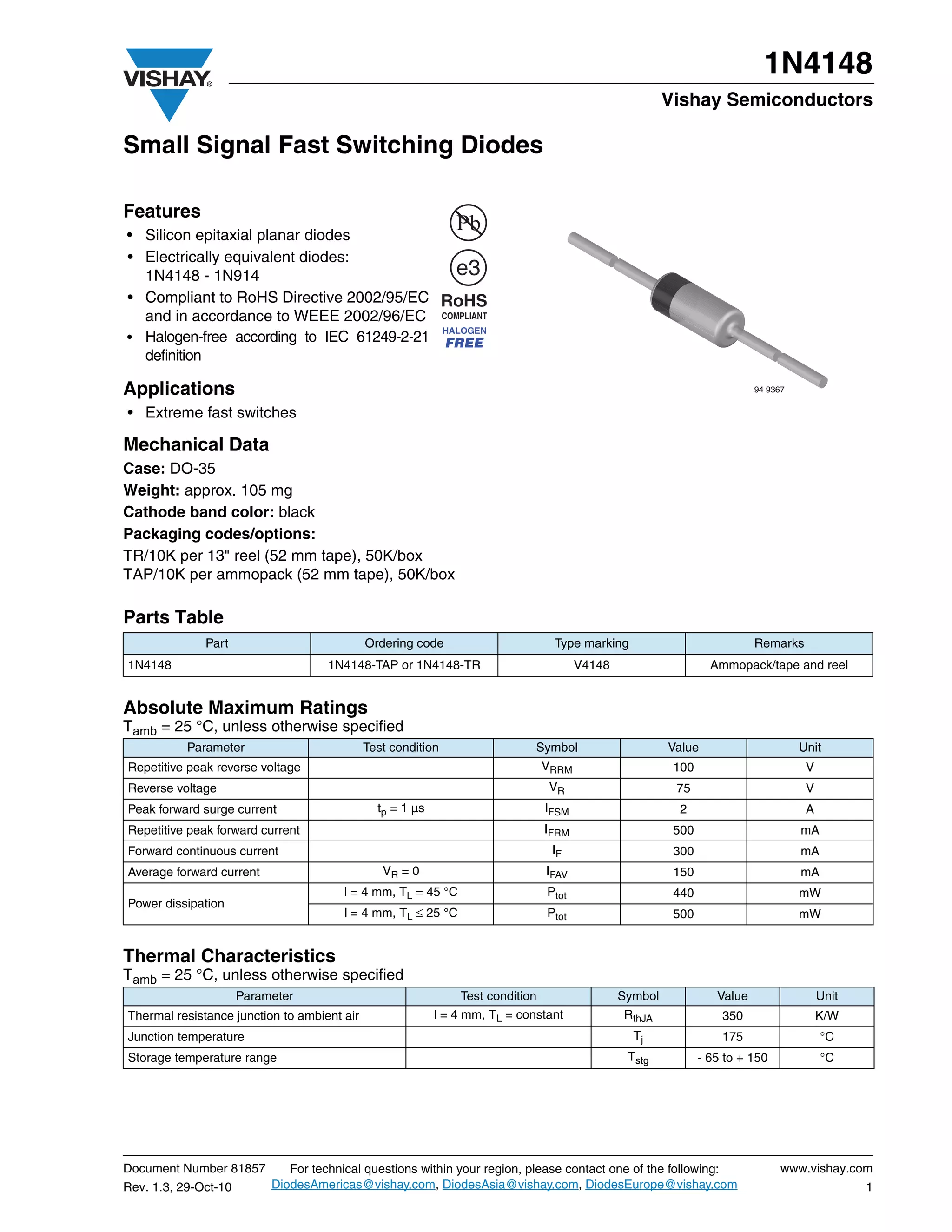
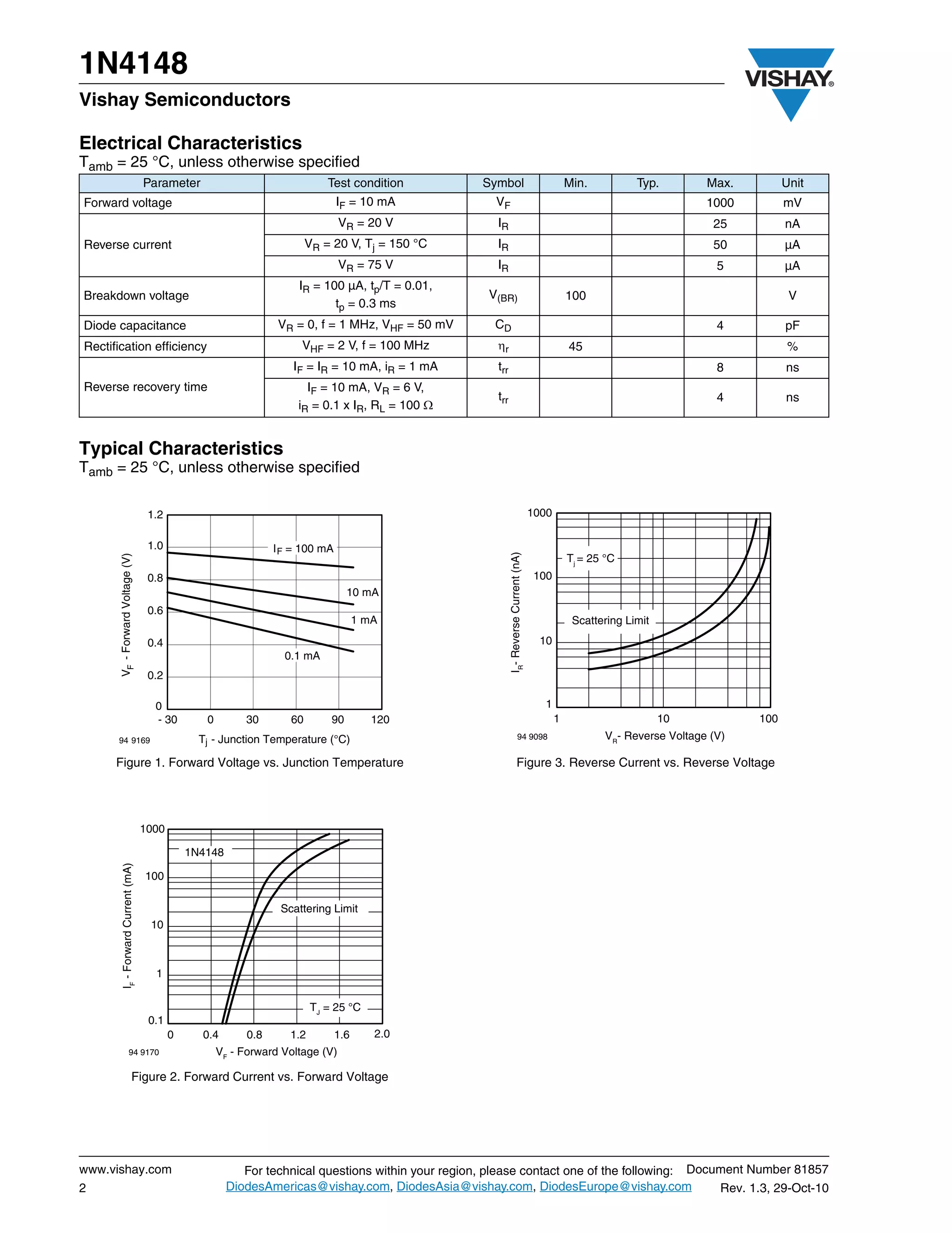
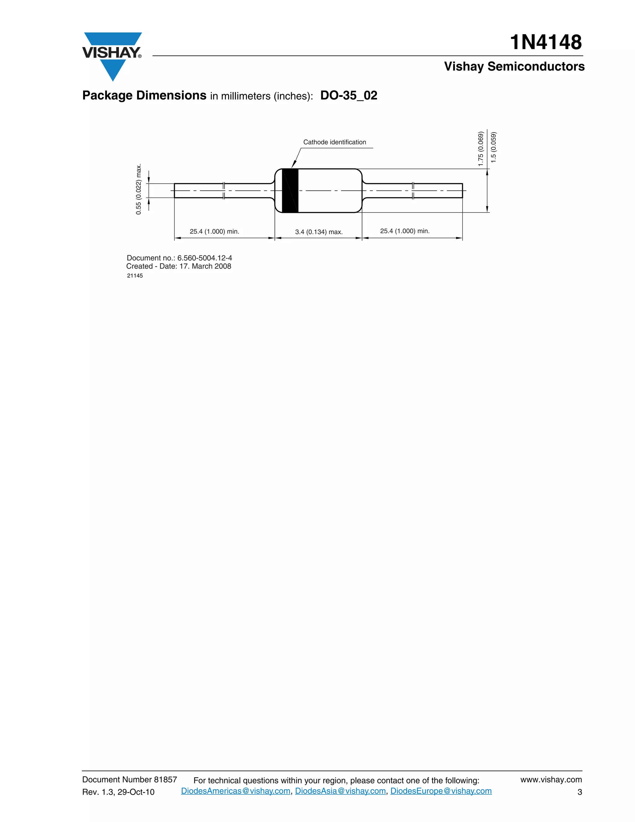
1N4148
                                                                                                        Vishay Semiconductors

Small Signal Fast Switching Diodes

Features
• Silicon epitaxial planar diodes
• Electrically equivalent diodes:
  1N4148 - 1N914
• Compliant to RoHS Directive 2002/95/EC
  and in accordance to WEEE 2002/96/EC
• Halogen-free according to IEC 61249-2-21
  definition

Applications                                                                                                              94 9367

• Extreme fast switches

Mechanical Data
Case: DO-35
Weight: approx. 105 mg
Cathode band color: black
Packaging codes/options:
TR/10K per 13" reel (52 mm tape), 50K/box
TAP/10K per ammopack (52 mm tape), 50K/box

Parts Table
              Part                           Ordering code                       Type marking                             Remarks
1N4148                               1N4148-TAP or 1N4148-TR                           V4148                     Ammopack/tape and reel


Absolute Maximum Ratings
Tamb = 25 °C, unless otherwise specified
           Parameter                         Test condition                  Symbol                     Value                       Unit
Repetitive peak reverse voltage                                                 VRRM                     100                         V
Reverse voltage                                                                  VR                      75                          V
Peak forward surge current                     tp = 1 µs                        IFSM                     2                           A
Repetitive peak forward current                                                 IFRM                     500                        mA
Forward continuous current                                                       IF                      300                        mA
Average forward current                         VR = 0                          IFAV                     150                        mA
                                       l = 4 mm, TL = 45 °C                     Ptot                     440                        mW
Power dissipation
                                        l = 4 mm, TL  25 °C                    Ptot                     500                        mW


Thermal Characteristics
Tamb = 25 °C, unless otherwise specified
                      Parameter                                Test condition                  Symbol             Value                  Unit
Thermal resistance junction to ambient air                 l = 4 mm, TL = constant             RthJA               350                   K/W
Junction temperature                                                                             Tj                175                   °C
Storage temperature range                                                                       Tstg           - 65 to + 150             °C


Document Number 81857         For technical questions within your region, please contact one of the following:                 www.vishay.com
Rev. 1.3, 29-Oct-10        DiodesAmericas@vishay.com, DiodesAsia@vishay.com, DiodesEurope@vishay.com                                            1
1N4148
Vishay Semiconductors

Electrical Characteristics
Tamb = 25 °C, unless otherwise specified
                                     Parameter                                 Test condition         Symbol                                         Min.          Typ.        Max.         Unit
Forward voltage                                                                   IF = 10 mA            VF                                                                     1000         mV
                                                                                  VR = 20 V              IR                                                                     25          nA
Reverse current                                                            VR = 20 V, Tj = 150 °C        IR                                                                     50          µA
                                                                                  VR = 75 V              IR                                                                      5          µA
                                                                        IR = 100 µA, tp/T = 0.01,
Breakdown voltage                                                                                      V(BR)                                         100                                     V
                                                                               tp = 0.3 ms
Diode capacitance                                                  VR = 0, f = 1 MHz, VHF = 50 mV       CD                                                                       4          pF
Rectification efficiency                                                VHF = 2 V, f = 100 MHz           r                                          45                                     %
                                                                       IF = IR = 10 mA, iR = 1 mA        trr                                                                     8          ns
Reverse recovery time                                                     IF = 10 mA, VR = 6 V,
                                                                                                         trr                                                                     4          ns
                                                                        iR = 0.1 x IR, RL = 100 


Typical Characteristics
Tamb = 25 °C, unless otherwise specified

                                      1.2                                                                                                 1000

                                      1.0                          I F = 100 mA
                                                                                                               IR- Reverse Current (nA)
       VF - Forward Voltage (V)


                                                                                                                                                     Tj = 25 °C
                                      0.8                                                                                                  100
                                                                                     10 mA
                                      0.6
                                                                                        1 mA                                                          Scattering Limit
                                      0.4                                                                                                   10
                                                                     0.1 mA
                                      0.2

                                       0                                                                                                     1
                                       - 30        0         30       60        90         120                                                   1                       10           100
      94 9169                                     Tj - Junction Temperature (°C)                                          94 9098                           VR- Reverse Voltage (V)

      Figure 1. Forward Voltage vs. Junction Temperature                                                                Figure 3. Reverse Current vs. Reverse Voltage


                                     1000

                                                1N4148
         IF - Forward Current (mA)


                                     100

                                                                    Scattering Limit
                                      10


                                       1


                                                                            TJ = 25 °C
                                      0.1
                                            0     0.4        0.8      1.2         1.6      2.0
                    94 9170                            VF - Forward Voltage (V)

                        Figure 2. Forward Current vs. Forward Voltage


www.vishay.com                                              For technical questions within your region, please contact one of the following: Document Number 81857
2                                                        DiodesAmericas@vishay.com, DiodesAsia@vishay.com, DiodesEurope@vishay.com               Rev. 1.3, 29-Oct-10
1N4148
                                                                                                               Vishay Semiconductors

Package Dimensions in millimeters (inches): DO-35_02


                                                                                                                    1.75 (0.069)
                                                                                                                                   1.5 (0.059)
                                                                  Cathode identification
              0.55 (0.022) max.


                                    25.4 (1.000) min.           3.4 (0.134) max.           25.4 (1.000) min.


           Document no.: 6.560-5004.12-4
           Created - Date: 17. March 2008
           21145


Document Number 81857                For technical questions within your region, please contact one of the following:                            www.vishay.com
Rev. 1.3, 29-Oct-10               DiodesAmericas@vishay.com, DiodesAsia@vishay.com, DiodesEurope@vishay.com                                                  3
Legal Disclaimer Notice
                                                                                                              Vishay

                                                  Disclaimer

All product specifications and data are subject to change without notice.

Vishay Intertechnology, Inc., its affiliates, agents, and employees, and all persons acting on its or their behalf
(collectively, “Vishay”), disclaim any and all liability for any errors, inaccuracies or incompleteness contained herein
or in any other disclosure relating to any product.

Vishay disclaims any and all liability arising out of the use or application of any product described herein or of any
information provided herein to the maximum extent permitted by law. The product specifications do not expand or
otherwise modify Vishay’s terms and conditions of purchase, including but not limited to the warranty expressed
therein, which apply to these products.

No license, express or implied, by estoppel or otherwise, to any intellectual property rights is granted by this
document or by any conduct of Vishay.

The products shown herein are not designed for use in medical, life-saving, or life-sustaining applications unless
otherwise expressly indicated. Customers using or selling Vishay products not expressly indicated for use in such
applications do so entirely at their own risk and agree to fully indemnify Vishay for any damages arising or resulting
from such use or sale. Please contact authorized Vishay personnel to obtain written terms and conditions regarding
products designed for such applications.

Product names and markings noted herein may be trademarks of their respective owners.


Document Number: 91000                                                                                    www.vishay.com
Revision: 18-Jul-08                                                                                                    1

1n4148

  • 1.
    1N4148 Vishay Semiconductors Small Signal Fast Switching Diodes Features • Silicon epitaxial planar diodes • Electrically equivalent diodes: 1N4148 - 1N914 • Compliant to RoHS Directive 2002/95/EC and in accordance to WEEE 2002/96/EC • Halogen-free according to IEC 61249-2-21 definition Applications 94 9367 • Extreme fast switches Mechanical Data Case: DO-35 Weight: approx. 105 mg Cathode band color: black Packaging codes/options: TR/10K per 13" reel (52 mm tape), 50K/box TAP/10K per ammopack (52 mm tape), 50K/box Parts Table Part Ordering code Type marking Remarks 1N4148 1N4148-TAP or 1N4148-TR V4148 Ammopack/tape and reel Absolute Maximum Ratings Tamb = 25 °C, unless otherwise specified Parameter Test condition Symbol Value Unit Repetitive peak reverse voltage VRRM 100 V Reverse voltage VR 75 V Peak forward surge current tp = 1 µs IFSM 2 A Repetitive peak forward current IFRM 500 mA Forward continuous current IF 300 mA Average forward current VR = 0 IFAV 150 mA l = 4 mm, TL = 45 °C Ptot 440 mW Power dissipation l = 4 mm, TL  25 °C Ptot 500 mW Thermal Characteristics Tamb = 25 °C, unless otherwise specified Parameter Test condition Symbol Value Unit Thermal resistance junction to ambient air l = 4 mm, TL = constant RthJA 350 K/W Junction temperature Tj 175 °C Storage temperature range Tstg - 65 to + 150 °C Document Number 81857 For technical questions within your region, please contact one of the following: www.vishay.com Rev. 1.3, 29-Oct-10 DiodesAmericas@vishay.com, DiodesAsia@vishay.com, DiodesEurope@vishay.com 1
  • 2.
    1N4148 Vishay Semiconductors Electrical Characteristics Tamb= 25 °C, unless otherwise specified Parameter Test condition Symbol Min. Typ. Max. Unit Forward voltage IF = 10 mA VF 1000 mV VR = 20 V IR 25 nA Reverse current VR = 20 V, Tj = 150 °C IR 50 µA VR = 75 V IR 5 µA IR = 100 µA, tp/T = 0.01, Breakdown voltage V(BR) 100 V tp = 0.3 ms Diode capacitance VR = 0, f = 1 MHz, VHF = 50 mV CD 4 pF Rectification efficiency VHF = 2 V, f = 100 MHz r 45 % IF = IR = 10 mA, iR = 1 mA trr 8 ns Reverse recovery time IF = 10 mA, VR = 6 V, trr 4 ns iR = 0.1 x IR, RL = 100  Typical Characteristics Tamb = 25 °C, unless otherwise specified 1.2 1000 1.0 I F = 100 mA IR- Reverse Current (nA) VF - Forward Voltage (V) Tj = 25 °C 0.8 100 10 mA 0.6 1 mA Scattering Limit 0.4 10 0.1 mA 0.2 0 1 - 30 0 30 60 90 120 1 10 100 94 9169 Tj - Junction Temperature (°C) 94 9098 VR- Reverse Voltage (V) Figure 1. Forward Voltage vs. Junction Temperature Figure 3. Reverse Current vs. Reverse Voltage 1000 1N4148 IF - Forward Current (mA) 100 Scattering Limit 10 1 TJ = 25 °C 0.1 0 0.4 0.8 1.2 1.6 2.0 94 9170 VF - Forward Voltage (V) Figure 2. Forward Current vs. Forward Voltage www.vishay.com For technical questions within your region, please contact one of the following: Document Number 81857 2 DiodesAmericas@vishay.com, DiodesAsia@vishay.com, DiodesEurope@vishay.com Rev. 1.3, 29-Oct-10
  • 3.
    1N4148 Vishay Semiconductors Package Dimensions in millimeters (inches): DO-35_02 1.75 (0.069) 1.5 (0.059) Cathode identification 0.55 (0.022) max. 25.4 (1.000) min. 3.4 (0.134) max. 25.4 (1.000) min. Document no.: 6.560-5004.12-4 Created - Date: 17. March 2008 21145 Document Number 81857 For technical questions within your region, please contact one of the following: www.vishay.com Rev. 1.3, 29-Oct-10 DiodesAmericas@vishay.com, DiodesAsia@vishay.com, DiodesEurope@vishay.com 3
  • 4.
    Legal Disclaimer Notice Vishay Disclaimer All product specifications and data are subject to change without notice. Vishay Intertechnology, Inc., its affiliates, agents, and employees, and all persons acting on its or their behalf (collectively, “Vishay”), disclaim any and all liability for any errors, inaccuracies or incompleteness contained herein or in any other disclosure relating to any product. Vishay disclaims any and all liability arising out of the use or application of any product described herein or of any information provided herein to the maximum extent permitted by law. The product specifications do not expand or otherwise modify Vishay’s terms and conditions of purchase, including but not limited to the warranty expressed therein, which apply to these products. No license, express or implied, by estoppel or otherwise, to any intellectual property rights is granted by this document or by any conduct of Vishay. The products shown herein are not designed for use in medical, life-saving, or life-sustaining applications unless otherwise expressly indicated. Customers using or selling Vishay products not expressly indicated for use in such applications do so entirely at their own risk and agree to fully indemnify Vishay for any damages arising or resulting from such use or sale. Please contact authorized Vishay personnel to obtain written terms and conditions regarding products designed for such applications. Product names and markings noted herein may be trademarks of their respective owners. Document Number: 91000 www.vishay.com Revision: 18-Jul-08 1