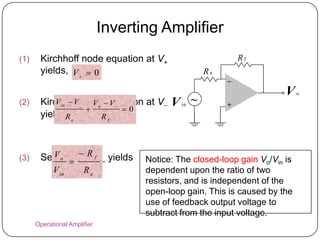
POTENTIOSTAT, CIRCUITRY, E-T
     WAVEFORMS AND
    ELECTROCHEMICAL
     MEASUREMENTS

              (GROUP 2)
   GROUP MEMBERS         MATRIC NUMBER
    NUR NADIAH BT           154982
      SAMSUDIN
 TUAN ZARITH FARHANA        154922
 BINTI TUAN ZAINUDDIN
  MUNIRA BINTI MAZLAN       151847
   NOOR AINI BINTI MD       154706
         SAAD
  SITI NUR ASMA‟ BINTI      151626
       MOHD AYUB
  ZALIKA AZREEN BINTI       153545
      ABD MANAN
 SUHAINIE BINTI ISMAIL      153598
ELECTROANALYTICAL
             METHOD
 Study an analyte by measuring the potential (volts)
  and/or current (amperes) in an electrochemical cell
  containing the analyte.
 3 main categories :
   - potentiometry : the difference in electrode
                      potential is measured
   - AMPEROMETRY           : the cell current is
  measured over
                      time
   - voltammetry : the cell current is measured
  while
                      actively altering the cells
  potential.
POTENTIOSTAT

 Potentiostat are amplifiers used to control a
 voltage between two electrode, a working
 electrode and a reference electrode, to a
 constant value
  ~ Reference electrode is used to maintain a
 constant voltage referred to the potential of
 the hydrogen electrode
  ~ Counter electrode is used to maintain a
 constant potential difference between the
 reference electrode and the working electrode
Function of Potentiostat

 To measure the potential difference between
  the working electrode and reference electrode
  without polarizing the reference electrode
 To compare the potential difference to a
  preset voltage and force a current through the
  counter electrode towards the working
  electrode in order to counteract the difference
  between preset voltage and existing working
  electrode potential
Characteristics of Potentiostat
1) Control speed
 Speed of a potentiostat is measured in terms of
  „small - signal rise – time‟, bandwidth rate.
 Potentiostats have bandwidths from 100 kHz to
  some MHz.
2) Accuracy
 The potentiostat counterbalances voltage
  difference between set control voltage and
  existing cell
3) Current range and dynamics
 High currents are required from the potentiostat.
4) Noise
 In potentiostats, the most sensitive circuit is the input
  stage, producing noise in the input resistor and the first
  amplifier stage.
 Good potentiostats are equipped with low-noise
  amplifiers.
5) Stability
VOLTAMMETRIC ANALYZER
   Advantages of the voltammetric analysis:
     i) High absolute sensitivity
     ii) Low cost of singular analysis
     iii) Multielement determination in one sample
     iv) Express analysis
     v) Safety for the operator
     vi) Excluding work with the metallic mercury
          (determination on the solid electrodes)
POTENTIOSTATIC CIRCUITRY

 Referred also as control circuitry.
 Main purpose:
i.   To maintain a voltage between the reference
     electrode and the working electrode
ii. To control the electro-chemical reaction
iii. To deliver an output signal proportional to the
     WE current
•    -Also provides the current to the counter
     electrode to balance the current required by
     WE
VOLTAGE RAMP GENERATOR
 A circuit that generates a sweep voltage which
 increases linearly in value during one cycle of
 sweep, then returns to zero suddenly to start the
 next cycle.

 Voltage ramp generator is formed- feedback
 resistor of the inverting voltage amplifier is
 replaced by a capacitor.

 If the input voltage, V1 is constant and RC = 1s
 then the output voltage Vit after a time t is given
                    Vo = Vo
 by:


 The output voltage rises steadily with time.
OPERATIONAL AMPLIFIER

 Is an extremely versatile electronic device.
 Versatility stems from the very high voltage
  gain together with high input resistance and
  low output resistance.
 Op-amp are direct coupled devices such that
  the input signal may be either AC or DC.
• All op-amp have two inputs connected in a
 differential mode, so that output voltage:
V₀ =A(V₊ - V₋)
V₊ = voltage at non inverting input
V₋ = voltage at inverting input
A = open loop gain of the op-amp
Operational Amplifier (Op-Amp)
 Very high differential gain                           +V   cc

                                       In p u t 1
 High input impedance                              +
                                                                  V   o
 Low output impedance                      V   d
                                                                        O u tp u t
 Provide voltage changes                           
                                       In p u t 2
  (amplitude and polarity)
                             R ~ in f
                                  in         -V R ~ 0    cc       out
 Used in oscillator, filter
  and instrumentation           Vo  G dVd

 Accumulate a very high
                               G d : differenti al gain normally
  gain by multiple stages                                5
                                          ver y large, say 10

   Operational Amplifier
Single-Ended Input
                 +                  • + terminal : Source
                            V   o
                                    • – terminal : Ground
~    V   i                          • 0o phase change
                 


                 +
                            V   o   • + terminal : Ground
                                    • – terminal : Source
                                   • 180o phase change

             ~
                 V   i


    Operational Amplifier
Double-Ended Input
                                   • Differential input
                +
V   d                     V   o
                                   •   Vd  V  V
    ~                              • 0o phase shift change
                                      between Vo and Vd


                +
                          V   o


~   V   1       
            ~
                V   2


Operational Amplifier
Common-Mode Operation
• Same voltage source is                       +
applied                                            V   o

  at both terminals                            
• Ideally, two input are equally   V   i   ~
  amplified
• Output voltage is ideally
zero
  due to differential voltage is
  zero
• Practically, a small output
  signal can still be measured
 Operational Amplifier
Ideal Op-Amp Applications
Analysis Method :
Two ideal Op-Amp Properties:
(1) The voltage between V+ and V is zero V+ =
    V
(2) The current into both V+ and V termainals
    is zero         +V   in
                                            V   o

                                   


                                       Rf
                              Ra

 Operational Amplifier
Non-inverting Amplifier
(1) Kirchhoff node equation at V+
    yields, V  V
                                                     V   in        +
                          i                                                V   o

                                                                   

(2) Kirchhoff node V o
         V   0 V   equation at V
                        0                                            Rf
    yields, a
            R       Rf                                        Ra


(3) Setting V+ = V– yields

      Vi       Vi  Vo              Vo          Rf
                         0   or         1
      Ra         Rf                 Vi          Ra


   Operational Amplifier
v+                                                                         v+
vi                            +                                  vi                                          +
                                                  vo                        R1                                                  vo
                                                                                      R2            v-
                         v-
                                                                                                            


             Ra                   Rf                                             Ra                              Rf

          Noninverting amplifier                       Noninverting input with voltage divider
                                  Rf                                              Rf                 R2
               v o  (1               )vi                   v o  (1                    )(                          )vi
                                  Ra                                              Ra           R1  R 2


                    v+                                                                         v+
                         +                               v   i                                           +
     vi                                                                                                                     v
                                             vo                         R   1
                                                                                               v-
                                                                                                                                o
                    v-                                                            R   2
                                                                                                         
                         


                             Rf                                                                              R   f

                                                                      Less than unity gain
           Voltage follower
                                                                                           R2
                  vo  vi                                               vo                                  vi
                                                                                      R1  R 2
          Operational Amplifier
Inverting Amplifier
(1)    Kirchhoff node equation at V+                          Rf
       yields, V   0                             Ra
                                                          
                                                                         V    o
(2)        V in  V
       Kirchhoff _nodeequation at V
                     V V
                     o    0
                                           V ~in          +
       yields, a
               R        Rf


(3)    SettingV = fV– yields
          Vo
                +
                  R
                                     Notice: The closed-loop gain Vo/Vin is
            V in       Ra            dependent upon the ratio of two
                                     resistors, and is independent of the
                                     open-loop gain. This is caused by the
                                     use of feedback output voltage to
                                     subtract from the input voltage.
      Operational Amplifier
COMPUTER READOUT

 Computer use digital signals (0 & 1) instead of analog
  signals (0-10 V)
 Interfacing a potentiostat with a computer requires
  translation back and forth
 Modern potentiostats have on-board DAC (digital to
  analog converters) and ADC (analog to digital
  converters)
External (strirrer, T, …)


01001010…         0-10 V
            DAC
                                   P-stat
            ADC
10010100…         0-10 V


                   External ( spectro, pH, …)
DAC   Digital to analog converter
      -Defines the smallest possible step
      - Multiple channels working as indipendent
      function generators
ADC   Analog to digital converter
      -ADC is a digital filter
      - Multi-channel ADC to convert several analog
      signals into digital
ANALYTICAL SOFTWARE -
   Autolab potentiostat
Autolab potentiostat
                               External (RDE, strirrer, T, …)


         01001010…            0-10 V
                     DAC

         01001010…             0-10 V
                     MODULE                   P-stat


         10010100…            0-10 V
                     ADC


                               External (QCM, spectro, pH, …)
Autolab potentiostat other D/A modules

 Scangen module: true linear scan generator
  Generates an analog scan (no staircase) with
   scan rates up to 250,000 V/s

 FRA module: frequency response analyzer
  Digital to analog sine wave generator
FARADAY CAGE
 3 conditions:
    - Very small currents are to be measured
  (current down to a few picoamperes)
    - The electrolyte has low conductivity
    - The reference electrode system has high
  source resistance
 make fast measurements of small currents.
 useful for eliminating electrical interference,
  especially line frequency noise.
 If the electrochemical cell is picking up electrical
  noise from the environment, the additional use of
  Faraday cage is strongly recommended
• Protect not just from static electrical charge but also from
electromagnetic waves; this is known as electromagnetic
shielding.
• This is how cars protect you from lightning: The charge is
conducted along the outer layer of the metal but does not
OXYGEN REMOVAL
 Most experiments require dissolved oxygen be
   removed from the cell.
 This is because:
i. Electrochemically active across the cathodic
     potential range
ii. Very likely to react with products formed by
     electron transfer
 To remove the dissolved oxygen:
i. The solution is purged with an inert gas (N2 or
     Ar) for 5 – 10 mins prior to the experiment
ii. A “blanket” of inert gas maintained above the
     solution during the experiment
Both cells have a fritted sparge tube to allow
deoxygentation of the solution with inert gas
Electrochem group 2

Electrochem group 2

  • 1.
    POTENTIOSTAT, CIRCUITRY, E-T WAVEFORMS AND ELECTROCHEMICAL MEASUREMENTS (GROUP 2) GROUP MEMBERS MATRIC NUMBER NUR NADIAH BT 154982 SAMSUDIN TUAN ZARITH FARHANA 154922 BINTI TUAN ZAINUDDIN MUNIRA BINTI MAZLAN 151847 NOOR AINI BINTI MD 154706 SAAD SITI NUR ASMA‟ BINTI 151626 MOHD AYUB ZALIKA AZREEN BINTI 153545 ABD MANAN SUHAINIE BINTI ISMAIL 153598
  • 2.
    ELECTROANALYTICAL METHOD  Study an analyte by measuring the potential (volts) and/or current (amperes) in an electrochemical cell containing the analyte.  3 main categories : - potentiometry : the difference in electrode potential is measured - AMPEROMETRY : the cell current is measured over time - voltammetry : the cell current is measured while actively altering the cells potential.
  • 3.
    POTENTIOSTAT  Potentiostat areamplifiers used to control a voltage between two electrode, a working electrode and a reference electrode, to a constant value ~ Reference electrode is used to maintain a constant voltage referred to the potential of the hydrogen electrode ~ Counter electrode is used to maintain a constant potential difference between the reference electrode and the working electrode
  • 4.
    Function of Potentiostat To measure the potential difference between the working electrode and reference electrode without polarizing the reference electrode  To compare the potential difference to a preset voltage and force a current through the counter electrode towards the working electrode in order to counteract the difference between preset voltage and existing working electrode potential
  • 5.
    Characteristics of Potentiostat 1)Control speed  Speed of a potentiostat is measured in terms of „small - signal rise – time‟, bandwidth rate.  Potentiostats have bandwidths from 100 kHz to some MHz. 2) Accuracy  The potentiostat counterbalances voltage difference between set control voltage and existing cell 3) Current range and dynamics  High currents are required from the potentiostat.
  • 6.
    4) Noise  Inpotentiostats, the most sensitive circuit is the input stage, producing noise in the input resistor and the first amplifier stage.  Good potentiostats are equipped with low-noise amplifiers. 5) Stability
  • 7.
    VOLTAMMETRIC ANALYZER  Advantages of the voltammetric analysis: i) High absolute sensitivity ii) Low cost of singular analysis iii) Multielement determination in one sample iv) Express analysis v) Safety for the operator vi) Excluding work with the metallic mercury (determination on the solid electrodes)
  • 9.
    POTENTIOSTATIC CIRCUITRY  Referredalso as control circuitry.  Main purpose: i. To maintain a voltage between the reference electrode and the working electrode ii. To control the electro-chemical reaction iii. To deliver an output signal proportional to the WE current • -Also provides the current to the counter electrode to balance the current required by WE
  • 11.
  • 12.
     A circuitthat generates a sweep voltage which increases linearly in value during one cycle of sweep, then returns to zero suddenly to start the next cycle.  Voltage ramp generator is formed- feedback resistor of the inverting voltage amplifier is replaced by a capacitor.  If the input voltage, V1 is constant and RC = 1s then the output voltage Vit after a time t is given Vo = Vo by:  The output voltage rises steadily with time.
  • 13.
    OPERATIONAL AMPLIFIER  Isan extremely versatile electronic device.  Versatility stems from the very high voltage gain together with high input resistance and low output resistance.  Op-amp are direct coupled devices such that the input signal may be either AC or DC.
  • 14.
    • All op-amphave two inputs connected in a differential mode, so that output voltage: V₀ =A(V₊ - V₋) V₊ = voltage at non inverting input V₋ = voltage at inverting input A = open loop gain of the op-amp
  • 15.
    Operational Amplifier (Op-Amp) Very high differential gain +V cc In p u t 1  High input impedance + V o  Low output impedance V d O u tp u t  Provide voltage changes  In p u t 2 (amplitude and polarity) R ~ in f in -V R ~ 0 cc out  Used in oscillator, filter and instrumentation Vo  G dVd  Accumulate a very high G d : differenti al gain normally gain by multiple stages 5 ver y large, say 10 Operational Amplifier
  • 16.
    Single-Ended Input + • + terminal : Source V o • – terminal : Ground ~ V i • 0o phase change  + V o • + terminal : Ground • – terminal : Source  • 180o phase change ~ V i Operational Amplifier
  • 17.
    Double-Ended Input • Differential input + V d V o • Vd  V  V ~ • 0o phase shift change  between Vo and Vd + V o ~ V 1  ~ V 2 Operational Amplifier
  • 18.
    Common-Mode Operation • Samevoltage source is + applied V o at both terminals  • Ideally, two input are equally V i ~ amplified • Output voltage is ideally zero due to differential voltage is zero • Practically, a small output signal can still be measured Operational Amplifier
  • 19.
    Ideal Op-Amp Applications AnalysisMethod : Two ideal Op-Amp Properties: (1) The voltage between V+ and V is zero V+ = V (2) The current into both V+ and V termainals is zero +V in V o  Rf Ra Operational Amplifier
  • 20.
    Non-inverting Amplifier (1) Kirchhoffnode equation at V+ yields, V  V V in +  i V o  (2) Kirchhoff node V o V   0 V   equation at V  0 Rf yields, a R Rf Ra (3) Setting V+ = V– yields Vi Vi  Vo Vo Rf  0 or  1 Ra Rf Vi Ra Operational Amplifier
  • 21.
    v+ v+ vi + vi + vo R1 vo R2 v- v-   Ra Rf Ra Rf Noninverting amplifier Noninverting input with voltage divider Rf Rf R2 v o  (1  )vi v o  (1  )( )vi Ra Ra R1  R 2 v+ v+ + v i + vi v vo R 1 v- o v- R 2   Rf R f Less than unity gain Voltage follower R2 vo  vi vo  vi R1  R 2 Operational Amplifier
  • 22.
    Inverting Amplifier (1) Kirchhoff node equation at V+ Rf yields, V   0 Ra  V o (2) V in  V Kirchhoff _nodeequation at V V V  o 0 V ~in + yields, a R Rf (3) SettingV = fV– yields Vo + R Notice: The closed-loop gain Vo/Vin is V in Ra dependent upon the ratio of two resistors, and is independent of the open-loop gain. This is caused by the use of feedback output voltage to subtract from the input voltage. Operational Amplifier
  • 23.
    COMPUTER READOUT  Computeruse digital signals (0 & 1) instead of analog signals (0-10 V)  Interfacing a potentiostat with a computer requires translation back and forth  Modern potentiostats have on-board DAC (digital to analog converters) and ADC (analog to digital converters)
  • 24.
    External (strirrer, T,…) 01001010… 0-10 V DAC P-stat ADC 10010100… 0-10 V External ( spectro, pH, …)
  • 25.
    DAC Digital to analog converter -Defines the smallest possible step - Multiple channels working as indipendent function generators
  • 26.
    ADC Analog to digital converter -ADC is a digital filter - Multi-channel ADC to convert several analog signals into digital
  • 27.
    ANALYTICAL SOFTWARE - Autolab potentiostat
  • 28.
    Autolab potentiostat External (RDE, strirrer, T, …) 01001010… 0-10 V DAC 01001010… 0-10 V MODULE P-stat 10010100… 0-10 V ADC External (QCM, spectro, pH, …)
  • 29.
    Autolab potentiostat otherD/A modules  Scangen module: true linear scan generator  Generates an analog scan (no staircase) with scan rates up to 250,000 V/s  FRA module: frequency response analyzer  Digital to analog sine wave generator
  • 30.
    FARADAY CAGE  3conditions: - Very small currents are to be measured (current down to a few picoamperes) - The electrolyte has low conductivity - The reference electrode system has high source resistance  make fast measurements of small currents.  useful for eliminating electrical interference, especially line frequency noise.  If the electrochemical cell is picking up electrical noise from the environment, the additional use of Faraday cage is strongly recommended
  • 31.
    • Protect notjust from static electrical charge but also from electromagnetic waves; this is known as electromagnetic shielding. • This is how cars protect you from lightning: The charge is conducted along the outer layer of the metal but does not
  • 32.
    OXYGEN REMOVAL  Mostexperiments require dissolved oxygen be removed from the cell.  This is because: i. Electrochemically active across the cathodic potential range ii. Very likely to react with products formed by electron transfer  To remove the dissolved oxygen: i. The solution is purged with an inert gas (N2 or Ar) for 5 – 10 mins prior to the experiment ii. A “blanket” of inert gas maintained above the solution during the experiment
  • 33.
    Both cells havea fritted sparge tube to allow deoxygentation of the solution with inert gas