
Recommended
More Related Content
What's hot
What's hot (18)
Similar to Error Proofing Projects
Similar to Error Proofing Projects (20)
Recently uploaded
Recently uploaded (15)
Error Proofing Projects
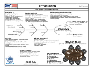
- 1. INTRODUCTION Quality Instruction Error Proofing - Proactive NOT Reactive MAN (PEOPLE) Give purpose to employees Build a winning Team Make them feel they belong (uniforms?) Guidance (write procedures) Training (Teach the procedures) Discipline (Enforce the procedures) Ideal Work Environment (Temp Control) METHOD (PROCESS) Organized (Number and Color scheme) Process Flow (Smooth / More steps = more errors) Standardized Work (Clear and easy to follow) Measure Progress Ideal Environment (Clean - Include in tasks) Cycle of Improving (Kaizen) put in to standards JHA / PPE & Ergonomics Assessment (Prevention) ENVIRONMENT (UNCONTROLLABLE) Implement Controls (Temperature and Humidity) Create Parameters by weather changes Sensors and Alarms added to detect temp & RH limits reached Work with suppliers to fine-tune material use limits (extend shelf life) Seasonal Planning Primary Cause LOOPHOLE : Basically, where you missed in planning (PFMEA) and now have to trace back. BREAKDOWN (Problem> Issue> Opportunity) ISHIKAWAISHIKAWAISHIKAWAISHIKAWA DIAGRAMDIAGRAMDIAGRAMDIAGRAM MATERIAL Create Receiving Inspections (use sample images) Train on the Inspections Hold suppliers to higher standard / Accountable Audit Suppliers Develop special products for your application (tweak formula) Standardize specifications of what you accept MACHINE (EQUIPMENT) Fine-tune Parameters Well written Start-Up procedures (operator inspections) Well written PMs (adjusted to meet production) Well Scheduled PMs Easy to follow Spec Sheets Calibrations current PROJECT TEAM (Never do alone / More perspectives = Less missed) PM - Project Manager S - Safety & Environmental E - Engineering QC - Quality Control P - Production T - Transportation F - Planning (forecasting) O - Open for new participant P PM S QC T F E O DESIGN (PLANNING) Develop revision process / Document control Create feedback / suggestions program Periodic review of industry trends Test products to point of failure and adjust specifications if needed. Secondary Cause Facility Location Closed-Loop system 80/20 Rule (unseen measures vs seen)SD143 - QA
- 2. METHOD Production Instruction Error Proofing Projects - Workstation Documents SAFETY Job Hazard Analysis PPE Assessment Ergonomics Assessment Particulate Flow Diagrams Traceability Reaction Plan / Flowcharts In-Line / Off-Line QC Checks Industry Standards / Line Layout / Op Preventive Maint. 1 2 COMMUNICATION SCALE (just the right information needed) All specific to one machine... Color code by department SAFETY QUALITY CONTROL PRODUCTION ENGINEERING / MAINTENANCE OPERATOR TRAINING Industry Standards / QC Alerts / Reports Calibration Certificates Preventive Maint. Startup Procedures Standardized Work Machine Operating Manual Reporting / Repair Procedures Assembly Parts / Drawings Machine Parameters / Schematics Spare Parts List PM Schedules /Lubricants Lockout Tag Out Procedures Material Handling / Staging EHS Setup Procedures / Machine Operation Product QC / Common Defects Packaging & Staging Finished Goods / Shipping 3 4 5SD143 - QA
- 3. METHOD Production Instruction Error Proofing - Standardized Work Development EXISTING INDUSTRY STANDARDS Line Layout / Op Preventive Maint. Startup Procedures Standardized Work Machine Operating Manual Reporting / Repair Procedures 3 PREVIOUS STUDIES (Do not reinvent the wheel) INTERNAL STUDIES (R&D) (for practical applications) MATERIAL VENDORS / SUPPLIERS (additional input - capabilities / limits) MACHINE VENDORS (additional input capabilities / limits) ESTABLISH PROCESS CAPABILITY CUSTOMER EXPECTATIONS (Higher Standard than norm) 007OL2 GL2 001 002 003 004 005 006 L4 A-2 BL3 IL2 NL4 Line 2 C-25Production Engineering Maintenance B1 I4 N5 G5 O2 Administration Quality Control Quality Control Quality Control Miami (MI) Welding Fabricatrion 2 Shipping Warehouse Storage Chemicals San Diego (SD) Los Angeles (LA) San Francisco (SF) Monterey Bay (MB) Corpus Christi (CC) Houston (HT) Shipping LOCATION FACILITY (I/A) DEPT. SEQUENCELINE / CELL WORK STATION CAPABILITY DEVELOP STANDARD WORK IMPLEMENT TRAINING PROGRAM (showing the WHY) ***Numbering / Code scheme follow mapping sequence to narrow down where it is located or refers to, just like an address on a map... SD-WLD-EG-L2-04-001 SD143 - QA Can use numbers to be consistent with accounting...
- 4. METHOD - PROCESS FLOW Production Instruction Flow in One General Direction - Error Proofing Projects MORE MOVEMENT = MORE ROOM FOR ERROR 6am- WEST DOCK (NORTH) NORTHEAST DOCK Each door represent time frame for shipping out. Out of time frame and door EARLY Drivers that show up early must be advised that pickup time starts as scheduled. Companies charge after waiting 2 hours & $300 if truck is cancelled too late (last 10am-12pm WEST DOCK (SOUTH) Incoming raw goods that are not used often in assembly. QC LAB PARTS - ABC ANALYSIS SD143 - QA RG - ABC ANALYSIS WEST DOCK (NORTH) Incoming raw goods that are used often in assembly. To stock location Stock to Line side In Process (Assembly) WIP (to next line / work cell) To final staging Load trucks / Ship DIVIDE IN TO SECTIONS TO DETERMINE FLOW
- 5. METHOD - FACILITY GO / NO GO GAGES Production Instruction Where QC meets Production Demands - Error Proofing Projects Thread Length Gage 8 5 2 GAGE DEVELOPMENT 1. Design Products / Design GO/NG Gages too 2. Critical measured areas 3. Write procedures for using gages & establish frequency. 4. Hang on shadow boards with workstation tools. 5. Train Operators Mating Parts: Male side gage (Holes) and female side (plugs) #6 Plug gage Gaps (Feeler gages) CUSTOM TO ALL SHAPES / SIZES Length (+tolerance) Tank Shape SD143 - QA Thread Gage BEND ANGLE / MANDREL DIAMETER Ø 5" 180⁰ Ø 6" 135⁰ Ø 6.5" 90º
- 6. MACHINE INTRO Maintenance Instruction Error Proofing Projects - Break up by components Manufacturer Label Catalog machine in CMMS. Enter top consumables and equivalents (assures right parts replaced down the road). Capacity meets machine specifications / needs. A2 SAFETY ITEMS JHA (Machine Guards, PPE, etc.), protect components too like air hoses and hydraulic lines so they do not get damaged. Vibration Control & Noise Reduction Mount [ISO 10816] LUBRICANTS DO NOT lubricate posted if needed. Create line diagrams with ideal angles / bow on line for least wear, etc. Oil, grease, etc. best for application calculated and posted. Drip / feed rate posted and marked out on dials. Create dial marks if none present.. One mark for each products application that you manufacture. SENSORS / ALARMS Draw attention to something you do not pay attention to 88 out of 90 times a day (example). Setup Easy to follow instructions (1 page with images) for each product you manufacture. 1. List problems / issues with machine (safety, QC, production, etc.) 2. List countermeasures (PFMEA) 3. Create error-proof ways for awareness and prevention. 4. Measures include: Documentation, Sensors and alarms, custom Gages, etc. TEMPERATURE CONTROLS Calculate allowable ranges. Post on machine. Place temp label add sensors and alarms. MECHANICAL Wear conponents on PM schedule. Speeds adjusted to match company schedule and application. Controls marked out. Lockout dials. Heat treat parts if applicable. MAX 150⁰⁰⁰⁰ PNEUMATIC Add pressure gages and mark out parameters, outline air hoses coming & going and routed throughout the machine. Create air flow diagrams to make errors stand out more. Calculate best hose angle / bow and install holders / guides. Best connectors for application & guard against damage. FASTENERS / CONNECTORS Type and size posted. Torque limits calculated and posted. Quick release or not. Replace with wing nut or not. CP48 ELECTRICAL Number scheme label. Panel box machine leads to labeled. Voltage range. 3 Phase. Schematics created. Amps, Hazard Labels, etc. Temp Controlled COOLANTS Hydro fluid, cooling fluids, water (see water system), etc. best for application calculated and posted. HOSES Label entry and exit points, whether changing over or not. Color scheme based on your own uses. Stock hoses are same and pre-measured. Create line routing diagrams with ideal angles / bow on line for least wear, etc. Spray Tips Whether cooling water, lubricant., protective coating, or finish coat, the fan pattern, angle, and amount of spray are critical in the quality of end product. Research best options for you product(s). SD143 - QA
- 7. MACHINE - FACILITY WATER Maintenance Instruction Temperature, Pressure, Composition, Flow / Direction - Error Proofing Projects Actuator (ERIE) Main water line / Flow limit 300psi / 160⁰F Water Pressure Gage Max should be almost twice your needed range. Range marked to assure within operating pressure. Some meters cannot work outside 3gpm Conductivity Controller ALARM Set at ideal levels for induction coils. Alarm notifies when outside levels & need to address. WATER VALVES Opened at ideal point to allow water flow at rate needed. Too little leads to overheating. Too much can cause leaks or hard water build up. Water Flow Direction Mark on pipes near valves to help troubleshoot leaks, etc. CoolingWater Temperature Control Unit (JCI) Can shut down cooling system if water goes beyond set point. Range -30 - 212⁰F 1 NOTE (EXAMPLES): *Valves should be fully open (handle in direction of pipe) *Cooling Water should be 70-80⁰ degrees max (>95⁰ = Work Order). *Water Pressure should be 30psi. *Heat exchangers - Need to cool down (temp gage) first before turning off. Bad for water and builds up deposits in tubing. *Need ALARMS for conductivity, temperature, and fill levels. Spray Nozzles Reduce build-up of hard water and prevent from clogging (leads to damaged products too hot for handling). Solenoid Valve (ASCO) Flow controls & signal to TDS Meter Routing Diagram Make sure all components are in proper place. to be effective. 2 345 Pump feeder TDS Meter sends feed signal. Dial set at feed rate needed. Keeps TDS down and lines cleaner. Mark feed rate range on dial. Cooling WaterWELD1 Label: Machine goes to Faster troubleshooting for spot welders, heat exchangers, induction coils, quench tanks, etc. ADD VISUAL ALARMS ADD ALARM SD143 - QA --OPEN-- --Closed-- Float Ball Keep fill level where needed. Pumps Should keep away from bottom to avoid pumping TDS back in to system.
- 8. MACHINE - FACILITY AIR SYSTEMS Maintenance Instruction Dewpoint, Pressure, Composition (Dryness), Flow / Direction - Error Proofing Projects Air Filters Adjust PM Schedules to replace if needed. Label schedule. Remove debris and contaminants from air lines that can cause premature machine wear. Differential Pressure gages Mark a marginal area (early warning) and MAX pressure on gages. Air Line Regulator Label pressure range. Reduce air pressure from facility compressor. Avoids damage to parts and regulates spray guns.Air line Lubricant Mark correct drip rate. Cylinders or any pneumatic moving parts will stick without lubricant. ADD ALARMS 1 Label: Machine goes to Faster troubleshooting. Cylinder (Pressure) Labeled Wrong pressure / cylinder, can damage parts and wear down components faster than expected life. NOTE: *Valves should fully open / closed *Flow rate should be ___ cfm. *Filters changed annually. *Air line lubricants are set to drip at ___ per hour? *Air Line regulators reduced to recommended pressure for machine function. Paint guns at 40psi, weld cylinders at ___, and filter blow down at 90-100psi. *Facility compressor output set at 150psi MAX. Routing Diagram Assures correct order for air flow to machines. 2 3 4Compressed AirSHEAR2 Routing Air Lines Assures correct bow and prevent damage by adding where guards need to go. Label direction of flow at connection points. SD143 - QA Dewpoint Meters Monitors levels for you. Connect to alarm inline. Compres
- 9. MACHINE - FACILITY PUMPS & MOTORS Maintenance Instruction Error Proofing Projects Manufacturer Label Capacity meets machine specifications / needs. Enter in to CMMS & equivalents. 1 Temperature Label Numbered Either for quick reference or by environment (1- Standard, 2-Severe, 3- MAX 150⁰⁰⁰⁰ Label MAX Temp ø___ CP48-12 Panel box leads to ADD ALARMS SD143 - QA STANDARD: 8hrs / <104ºF / Clean SEVERE: 16hrs+ / <122ºF / Moderate Dirt EXTREME: 16hrs+ / >122ºF / Severe Dirt LOW TEMP: -20ºF Vibration Control & Noise Reduction Mount [ISO 10816] NOTE (EXAMPLE): *Store in 50⁰-120⁰ max. No more than 60% relative humidity (rust formation on bearings). Implement controls. *Lubrication schedule based on Frame size + RPMs + Severity of Service (Environment). *Disconnect motor before lifting. *Do not lift by motor hardware, use eye-bolts. *Avoid rapid temperature changes when handling (condensation builds inside). *Minimum resistance of motor winding insulation is 5 Meg ohms. *Shock or vibration must not exceed 2 mils maximum at 60 hertz, to prevent the bearings from brinelling. *Pumps / Pipes outside storage tanks must be away from bottom to avoid pumping sediment (TDS / settled material) back in to system. ø___ fitting Do Not / Lubricate Sticker Some bearings do not need lubrication DO NOT LUBRICATE LUBRICANT USED 1 Machine Guard in place? Polyrex EM (Exxon Mobil) Label Ports by Standards Grease Speed Control Parameters marked DC44 Dow Corning DC44 < High Temp Grease (over >122ºF) <60%RH
- 10. MACHINE - EQUIPMENT MODIFICATIONS Maintenance Instruction After Market Perfromance Parts Added - Error Proofing Projects AZO Sieve Screen (PT03102) For removing clumps of powder out of the spray system. Helps prevent gun CONNECTIONS (IN SEQUENCE) 1) Accumulator Vent 2) Infeed Powder Tube from Shuttle 3) Accumulator Powder Inlet #1 (TP1) 4) Accumulator Inlet #2 (TP2) 5) Accumulator Inlet #3 (TP3) 6) Accumulator Inlet #4 (TP4) 7) Trash hopper 8) Injector #1-2 (G01-G02) 9) Injector #3-4 (G03-G04) 10) Injector #5-6 (G05-G06) 11) Injector #7-8 (G07-G08) 12) Grounding Cable 13) IMF Efector 14) Hopper Fluidizing Air Hose Vent Assist Air fitting 3-250/50 Mini Cyclone Recycles powder back down in to hopper. Research options for best flow, based on material size (gravity). [1] [3-6] [7] [2] AZO Feed Hose Needs to have grounding wire, durable to where powder does not wear inside quickly. Bow is minimal to last longer & have smoother flow. Magnetic Separator (FF4600) Removes metal shards left on frames from blast cleaning. Helps eliminate Holidays. Part of start-up checks. the spray system. Helps prevent gun clogging and uneven application. Wears down & tears. Part of start-up Suction Tube Sends powder up to injectors and out to spray guns. Modify length to hover above sediment on bottom. Wears down over time. On ANNUAL PM. IMF Efector Sensor reads level of powder in Hopper and tells the shuttle to send more when low. Has gotten dirty and failed to work before. Part of start-up checks. Fluidizing Membrane Keeps the powder flowing smoothly and not allowing to settle. On ANNUAL PM. Sieve Air Volume Controls (226703) Parameters marked out to assure air flow is within the set range. Easy to audit. Keep AZO bearings from locking up and assures smooth flow. ITW Gema Injectors (x2) Has a sleeve inside that wears down and needs to be blown out daily & replaced roughly every 3 months. Part of start-up Connection Points [#] Number the connection tubes for faster and accurate changeovers. Operators cross tubes when changing over and troubelshooting takes longer. [12] [8-9] [13] [14] DAILY MONTHLY ANNUALLY INSPECTION SCHEDULEADD ALARM [10-11] GROUNDING Best methods / Fire Hazards Wheels Modify for easier movement during product changeover. SD143 - QA
- 11. MACHINE - DIPPING / COATING OPERATIONS Maintenance Instruction Dip Tank Coating Applications - Error Proofing Projects Dipstick Hole Check tank levels easier. VOCs / Usage & Evaporation Rate Agitators Size (HP) determined by material thickness and volume of tank. Prevents material from settling on bottom. Heavier material needs more powerful motors and props. Best practice is either using pumps on the bottom or 1 prop for every 2-3' deep of material and 1 motor for every 3' surface area. Props must bring sediment upward as it settles. Downward rotation would push sediment to bottom. Coating Surface Area covered 165' Range Humidity / Temperature Control Units / Alarms Notification to bring attention to conditions out of the control limits. Monitoring becomes too routine and may become neglected. This assures that measures are taken to prevent coating operations outside allowable ranges. Some have ranges (165'+) where you can keep the receiving end in your office to monitor. Others are capable of connecting to alarms and some are Data Loggers to see trends and find areas needing improvements. Tank ID For repair orders 52s 39s 26s Zahn 1-4 VOCs / Usage & Evaporation Rate Air Board regulation (California) requires to keep covered when not in use and monitor daily. Can use MS Excel to create VOC formulas based on surface area drop (e.g. 1" = 30gal x__ VOC per gallon). Establish allowable limits based on permits and mark tank as reference to NOT exceed that limit per day. 2.5' Impellers as close to bottom as possible to lift sediment. SD143 - QA Emergency Drain Valve OSHA did require emergency drain valve. Last CFR update, it may have been removed. Pipe diameter had to be based on capacity of tank. (e.g. 1500g = 3" O.D.) Viscosity (QC) Most coatings for dipping only needs to be 1.5-2.0mils thick. Evaporation of mixed solvents cause to get thicker, leaving clumps and wasting product. Poor QC. Create a viscosity scale based on internal studies for thickness results. Measure with Zahn cup based on suplplier recommendations. Wet Film Thickness (WFT) Gage Measures thickness based on solids in material composition. Create a formula sheet showing Dry Film Thickness (DFT) based on wet film thickness. Wheels Modify for easier movement during cleanup / spills.
- 12. MACHINE - PAINTING / COATING OPERATIONS Maintenance Instruction Paint Booth Applications - Error Proofing Projects Humidity / Temperature Control Units / Alarms Notification to bring attention to conditions out of the control limits. Monitoring becomes too routine and may become neglected. This assures that measures are taken to prevent coating operations outside allowable ranges. Some have ranges (165'+) where you can keep the receiving end in your office to monitor. Others are capable of connecting to alarms and some are Data Loggers to see trends and find areas needing improvements.165' Range Differential Pressure Gage Mark a marginal area (early warning) and MAX pressure on gages. Air Line Regulator Label pressure range. Reduce air pressure from facility compressor. VOCs MUST use High Volume Low Pressure (HVLP) guns. Air Board regulation (California) requires to monitor daily. Can use MS Excel to create VOC formulas based on how many gallons used (e.g. 2gal x__ VOC per gallon). Establish allowable limits based on permits and post at mixing station as reference to NOT exceed that limit per day. SD143 - QA Dial in Thickness Coatings for spray applications varies in thickness by customer needs. Establish what 1 FULL coat should be (feedback from suplier). Do an internal study based on best coverage and thickness. Establish a formula sheet for customer demands. Can use a Wet Film Thickness (WFT) Gage based on solids in material composition. Create a formula sheet Fan Pattern Based on guns used (HVLP) and your internal study on thickness, determine what direction your fan pattern should go & how far away you need to have the gun. Make a Standard for this operation / train operators. pressure from facility compressor. Regulates spray guns to assure operators do not exceed lhigh volumes (leads to waste & poor coat quality), even with controls on the spray guns.
- 13. MACHINE - FACILITY WELDING Maintenance Instruction Poor Welds / Less Down Time - Error Proofing Projects Program Lockout Prevents operators from changing parameters to compensate for other wear items or poor setup. ~ Resistance Welder ~ Wire Feeder Post Wire feed speed ranges & voltage (AUDIT) to better control process. Multiple weld stations close to each other should be labeled to distinguish which weld gun the wire runs to. Place out of way on swivel so operators can move back & forth to weld jigs. Use best parts to avoid tangles. Program Must stop if weld undetected. Electrodes / Shunts Welder Voltage & Amp range marked to assure within limit based on material thickness. Easier for QC Audits. 645645645645 234234234234 Cooling Water Refer to facility water sheet. 1 Weld Map (Trim Masters Inc.) Location of welds & assign weld numbers based on electrode it came from. Faster troubelshooting when analyzing a weld failure. Weld length legend to show length of welds by color. Subparts & thickness listed for voltage needed. NOTE(s): EXAMPLE *Shunt type / size / locations should be labeled to assure correct replacement *Shielding gas flow rate should be ___ cfm. . *Wled Condition sheet (parameters determined) placed in SOP Binder for reference / audits. Electrodes / Shunts Boundary samples to establish wear points and stock replacements. Routng diagrams Proper grounding and workpiece position. Proper bow for weld gun cable (liner - use spring accessory). W1-030110-S1-045 For multiple weld stations, assign an ID number to trace what welder and operator it came from. This can be a label placed on the rack the products are stacked on. Example: Welder 1, March 10th, 1st Shift, Operator 045 Liner Bow / Angle Reduces wear on cable, reducing tangles (downtime) and extending life. SD143 - QA Weld Curtains 2' off ground (ventilation). Tinted (flash) / Retractable?
- 14. MACHINE - CONVEYORS Maintenance Instruction Markers, Material, Sensors & Alarms - Error Proofing Projects SPACING Shape Detection Optical micrometers. Verifies correct shape. Time Sensitive (Curing / Cooling) When using timers, being able to see conveyor marks lining up with products coming out of an oven, powder booth, shear, etc, assures correct parameters (settings). Easier to audit when walking by the line. Material Static free, high / low temperature, high strength, cut resistant, chemical resistant, flame retardent, high / low friction, etc. Best for application MarkersMotion Alignment When parts / products are a designated width or start moving off to the side & Temperature Check / Counter Connected to nozzles, sprinklers, air knives, heaters, etc to cool or heat products before offloading, if temperature outside of proper range. SYSTEM CONFIGURATION (OPTIONS) 8" 16" 20" Weight Sensors SD143 - QA Markers Quick reference to assure correct lengths of products, correct spacing, etc. Light Curtains Besides safety, also used to detect overstacking (height limits), height variations, etc. Spacing Verify products are traveling evenly. Motion JAM detection. Sets alert if products are not moving & conveyor is. width or start moving off to the side & need to fit into another stage, alerts before they jam. Metal Detector Non-metallic materials, pertinent to not contain metals.
- 15. High Low PrecipitationRelative HumidityDewpoint January 53 37 2.2 83 40 February 59 39 1.8 76 42 March 66 42 1.7 68 42 April 73 46 1 60 45 May 80 51 0.5 52 47 June 88 55 0.1 46 49 July 94 58 0 41 52 ENVIRONMENT - FORECASTING Production Instruction HIGHS, LOWS, PRECIPITATION, RELATIVE HUMIDITY, DEWPOINT United States Average Temperatures Facility Location California Annual Average 60 70 80 90 100 Precipitation Reduce Temp Controls Increase Temp Controls July 94 58 0 41 52 August 92 57 0 45 52 September 87 54 0.2 51 52 October 77 48 0.5 57 47 November 65 40 1.1 70 42 December 55 37 2 81 40 FIELD SUPERVISOR EQUIPMENT SUPERVISOR QUALITY SUPERVISOR TEAM LEAD AUTHOR(s) Doc# LA-SFD-QA-310-028 Ron Fife Rev 1 DATE DATE DATE DATE DATE: 12.05.1996 DATE: 09.09.1998 Facility Location California Annual Average Precipitation 1961-1990 0 10 20 30 40 50 60 High Low Relative Humidity Dewpoint Temperature(Degrees) SD143 - QA
- 16. Easy to Follow Controls - Error Proofing Projects AIR VOLUME: Factory recommended setting is 4.0 Nm³/h with a 60% Powder Output (we use 3.5 Nm³/h with 30%) KV's: High Voltage setting. Factory Preset with #8 in 100 to wrap the bars more consistently. RINSING AIR: Based on Nozzle Used (air flow is measured in Nm³/h). Use SELECT (#9) to navigate here. Should be 0.2 for our use. POWDER INPUT RATE: Changes the amount of powder flow for THICKNESS. Range should be 30- 60% MAX by bar size. MICRO-AMPS: Controls the Spraying Current. Factory Preset with #8 is 22µA. Helps conformity and coating thickness consistency. MAN - TRAINING / DIRECTION Production Instruction 2 11 2 5 3 4 3 4 5 7 9 6 10 SELECT: Use with #5. Switch between display levels. Navigates to Rinsing Air (top right) and Shaping Air (optional) setting on the Injectors. REMOTE PLC CONTROL: Not applicable with our use or processes. POWER: Used when only running a couple guns. Otherwise MAIN Power shut down is used. Dowel Ends only will apply to this. PROGRAM NUMBER: These are preset based on Process Capability studies and should not be changed without QC Approval. PROGRAM CHANGE: This is part of Set-Up procedures based on Basket SIZE. Follow your Parameters Guide (Program Settings). APPLICATION MODE: Used for complicated parts with depressions (PROFILES). This is what we use. Guns MUST be at 8" away. here. Should be 0.2 for our use.7 8 6 7 8 9 10 11 11 IF COATING THICKNESS CHANGES, VERIFY SETTNGS. DO NOT CHANGE THEM UNLESS THEY DO NOT MATCH PARAMETERS GUIDE. TROUBELSHOOT HEAT AND CONVEYOR SPEED NEXT... LA-310-PNT-019 Rev. 0 1/13/14
- 17. START: Must be on HOME Screen. Used to initiate induction heating from panel. The HeatOn light (#11) will come on. STOP: Halts the induction heating operation. Easy to Follow Controls - Error Proofing Projects MAN - TRAINING / DIRECTION Production Instruction SOFT BUTTONS: Used to select specific features. Operators do not use these buttons, only maintenance and supervisors. HOME: Use this button to take you back to the Home screen. SELECT: Use Select buttons to highlight SETPOINT or 2 1 3 4 3 4 6 10 7 8 9 11 5 SELECT: Use Select buttons to highlight SETPOINT or TIMER and to scroll through onscreen lists. ADJUST: Use these buttons to adjust on-screen figures such as SETPOINT, TIMER, etc. FREQUENCY: This is the RF output frequency when HeatOn. It is the resonant operating frequency. TIMER: Used to count-up, count-down, or continuous. Note (T) timer or (C) count up displayed near arrow. SET POINT: Output level based on heat required. Varies by bar size & line speed. Refer to chart. Use ◄/► buttons to increase or decrease. OUTPUT: V or kW when heating in progess. Higher # equals faster heating / hotter parts. Use ◄/► buttons to increase or decrease. STATUS: Ready, Heat On, Limiting, and Fault. See LED lights displays to the left. 1 52 6 7 8 9 10 11 READY: EKOHEAT is waiting to heat; no faults detected. HEAT ON: START command received, outputting power per settings. FAULT: Heating interrupted; fault detected; correction required. Read display for information about the Fault. LIMITING: Either the Voltage, Power or Temperature values have reached their maximum limits.
- 18. START: Used to initiate induction heating from panel. TEMP DIAL: Set the temperature of the oven based on BAR SIZE. Follow parameter sheet posted at the workstation. STOP: Halts the induction heating operation. POWER ON / OFF: Main power that needs to be ON before starting machine. MAIN BREAKER ENABLE: If the main breaker is tripped, and then reset, the light will come on. MAN - TRAINING / DIRECTION Easy to Follow - Error Proofing Projects Production Instruction 2 1 1 3 4 3 4 5 6 7 8 9 5 GROUND CURRENT: Must stay within 0.1 - 0.8 during normal operation. If meter reads higher, check grounding of the bars. GROUND / GROUND RESET: If light is on, the ground needs to be reset. Check the grounding of the bars. READOUT DISPLAY: % VOLTS (80-85), % AMPS (90-95), % KW (80-85), CONDUCTANCE (120-125), FREQUENCY (944-950), & FAULT CODE. TEMPERATURE PRESSURE METER: Goes with #8. Will show the readout based on position selected. POSITION 1) Inside Air Temp <100⁰F, 2) Inlet Water Temp <90⁰F, 3) Inlet water pressure 50-60PSI, 4) Outlet water Pressure 3-5PSI. 10 2 6 7 8 9 10 100⁰ 90⁰80⁰ 70⁰ MAX 90⁰INLET - from Heat Exchanger OUTLET - to Heat Exchanger
- 19. (1) MATERIAL HANDLER 1. Operator sees he is getting low on material. 2. Moves switch to "Material Handler" & turns ON. 3. Material Handler light comes on & unique sound activated. 4. Material Handler comes over and loads infeed to keep line running. (2) MAINTENANCE 1. Operator needs maintenance support. 3. Maintenance light comes on & unique sound activated. 4. Mechanic arrives to assist and repair machine. (3) SUPERVISOR 1. Operator needs a Supervisor to escalate a situation. 2. Does not leave workstation to look for mechanic. Moves switch to Maintenance & turns ON. Clears area to prepare for mechanic. ANDONS - WORKSTATION Material Handler Maintenance Supervisor ON OFF 1. Operator needs a Supervisor to escalate a situation. 2. Does not leave workstation. Activates Andon, etc… 1 2 3 SD143 - QA
- 20. (1) MATERIAL HANDLER 1. Operator sees he is getting low on material. 2. Moves switch to "Material Handler" & turns ON. 3. Material Handler light comes on & unique sound activated. 4. Material Handler comes over and loads infeed to keep line running. (2) MAINTENANCE 1. Operator needs maintenance support. 3. Maintenance light comes on & unique sound activated. 4. Mechanic arrives to assist and repair machine. (3) SUPERVISOR 1. Operator needs a Supervisor to escalate a situation. 2. Does not leave workstation to look for mechanic. Moves switch to Maintenance & turns ON. Clears area to prepare for mechanic. ANDONS - COMM BOARDS Material Handler Maintenance Supervisor ON OFF 1. Operator needs a Supervisor to escalate a situation. 2. Does not leave workstation. Activates Andon, etc… ***Large Communication boards are located in a centralized area and visible to all employees. The Workstation would light up with a unique sound (related to personnel needed), indicating the workstation needed assistance. This was in case the personnel needed were too far away from the area. Press 01 Press 02 Press 03 Saw 01 Saw 02 Welder 01 Plasma Cttr Bender 1 Welder 02 Laser Cttr Bender 2 Welder 03 Threader 1 Tapper 1 Welder 04 Threader 2 Tapper 2 Welder 04 Punch ShearN SD143 - QA