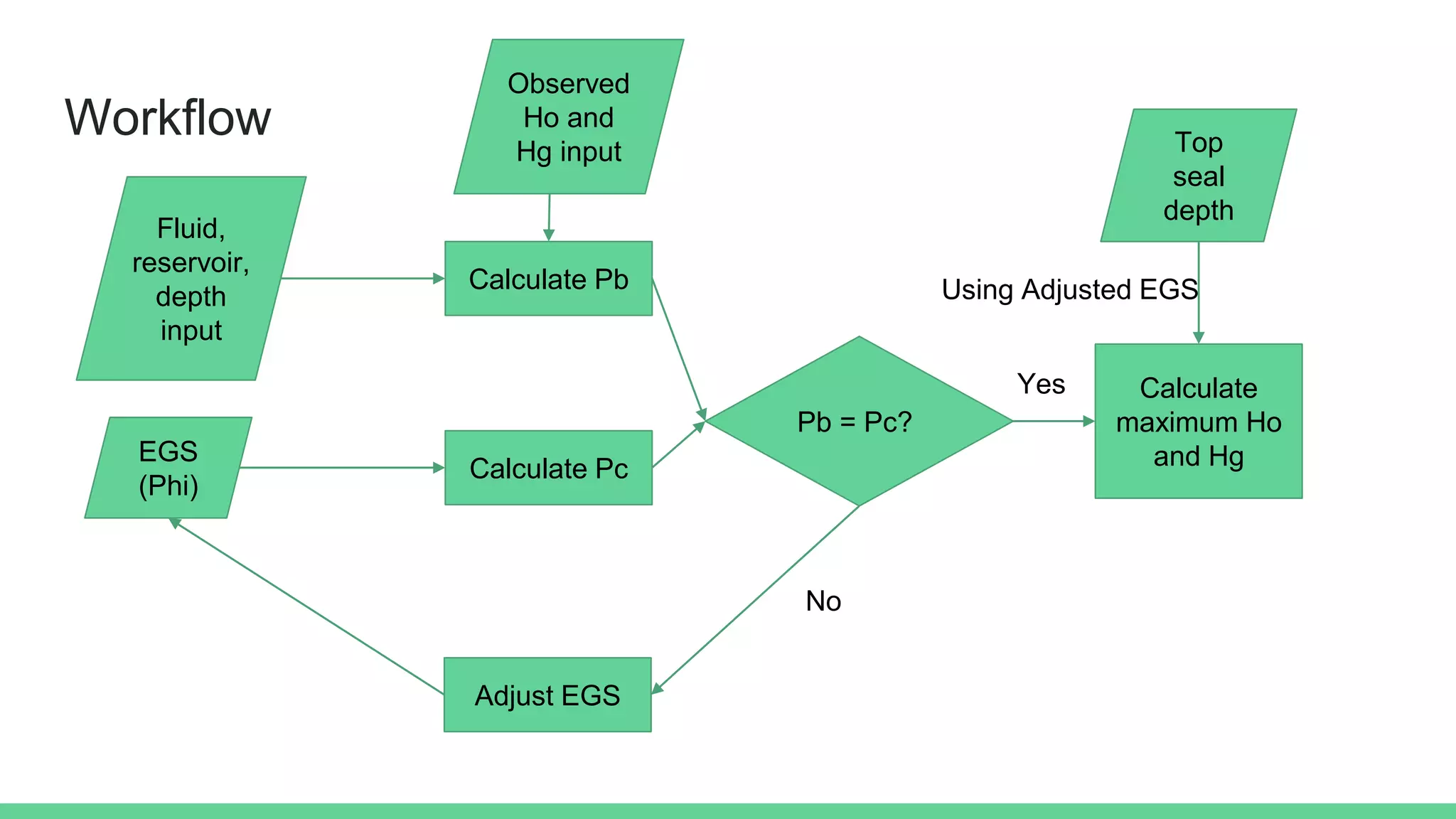
1) The Equivalent Grain Size (EGS) method provides a way to assess seal capacity for carbon capture and storage based on the relationship between pore throat size and fluid column height.
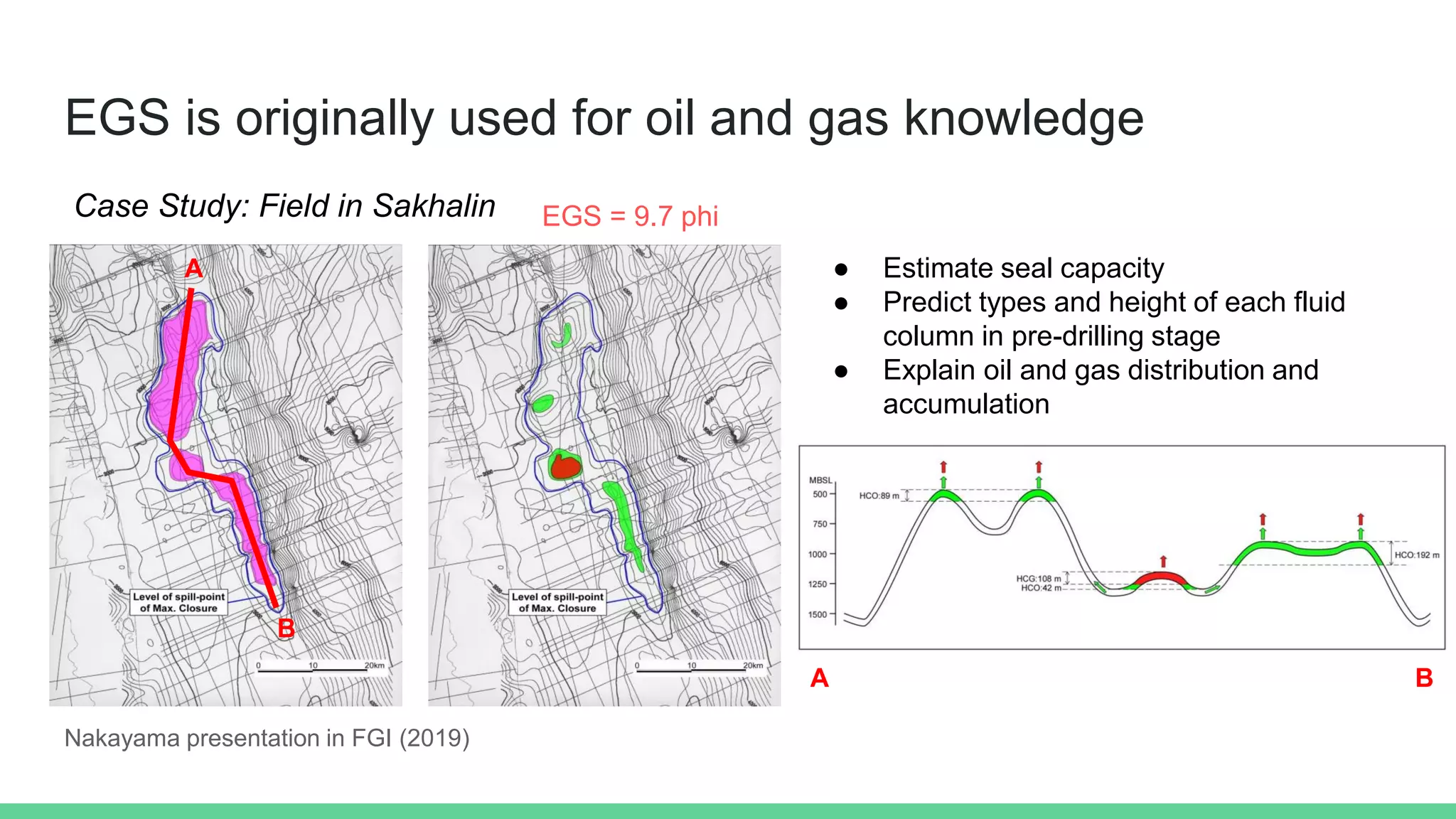
2) Case studies have shown that the height of a CO2-gas column injected into a reservoir is controlled by the seal's EGS, with a higher EGS allowing a taller fluid column before reaching hydrostatic equilibrium.
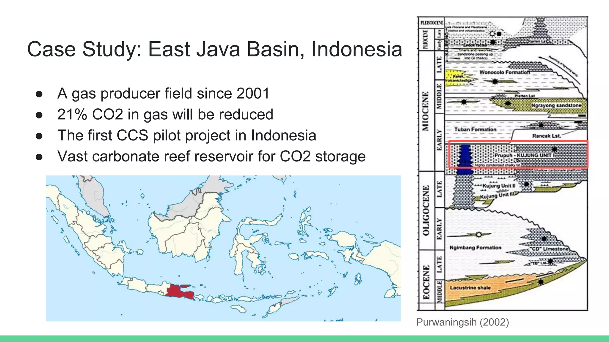
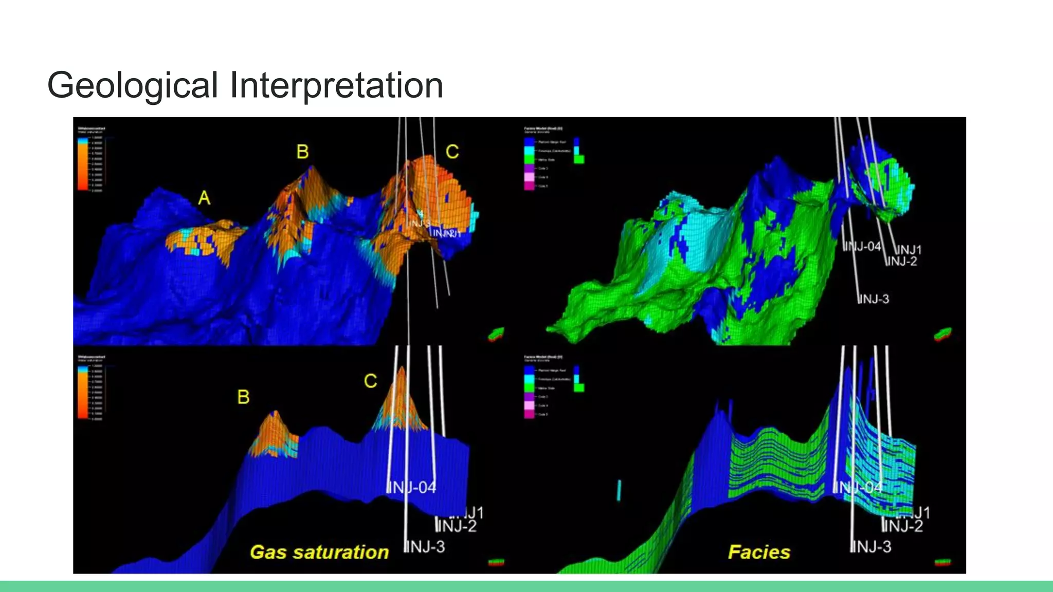
3) Application of the EGS method to a gas field in East Java, Indonesia indicated that CO2 could safely be injected and stored in the carbonate reef reservoir due to the seal's estimated EGS and separation from the main reservoir by facies changes.


![Recommended Reading
● EGS original paper in AAPG Memoir: Sawamura, F. and K. Nakayama.
[2005] Estimating the amount of oil and gas accumulation from top seal and
trap geometry, in R. Sorkhabi and Y. Tsuji, eds., Fault and fluid flow, and
petroleum traps, AAPG Memoir 85, 33-42.
● Geology and simulation of CCS in this location: Nuwara, Y. [2020] Integration
of Reservoir. Rock Physics, Seismic, and Geomechanical Modelling for CO2
Injection in Carbonate Reef reservoir, EAGE 82nd Annual Conference and
Exhibition.](https://image.slidesharecdn.com/egseagepresentation-210919071325/75/Equivalent-Grain-Size-Method-for-Sealing-Capacity-Assessment-in-CCS-16-2048.jpg)