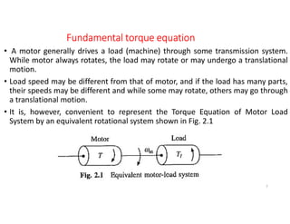
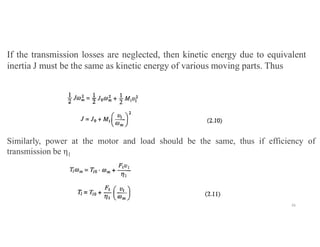
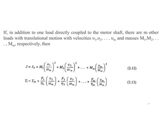
1) The document discusses the torque equation that describes the relationship between the torque developed by an electric motor and the load torque in electric drive systems. It explains that the torque developed by the motor must exceed the load torque by an additional amount to overcome the inertia of the drive system during acceleration.
2) It describes different types of load torques, including active loads that can drive the motor under equilibrium conditions, and passive loads that always oppose motion. It also discusses components of load torque such as friction, windage, and torque required for useful mechanical work.
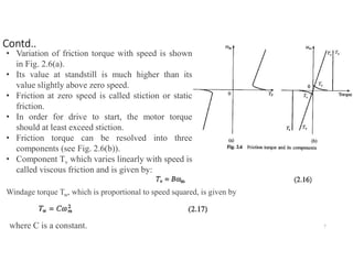
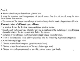
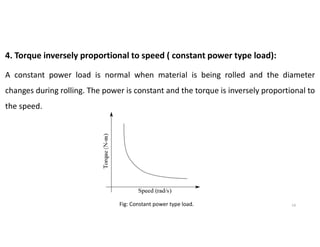
3) It outlines common speed-torque characteristics of different load types, including constant torque, torque proportional to speed, torque proportional to the square of speed,