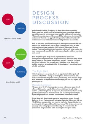
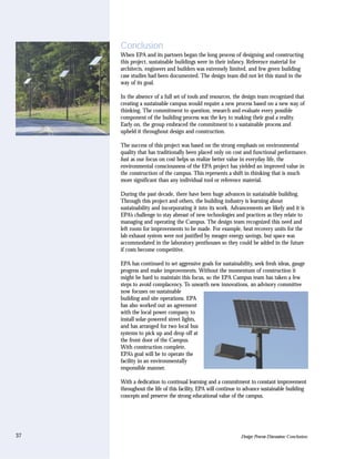
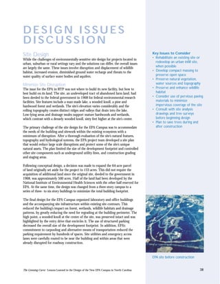
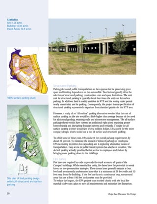
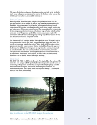
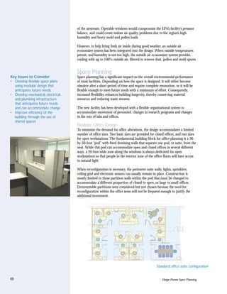
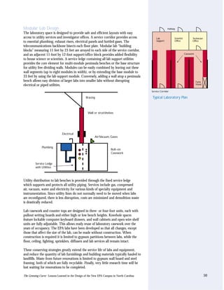
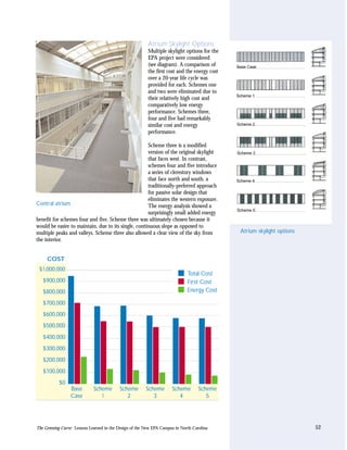
Download to read offline

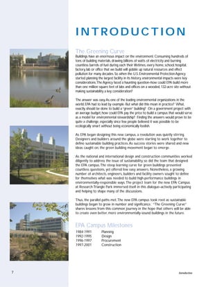

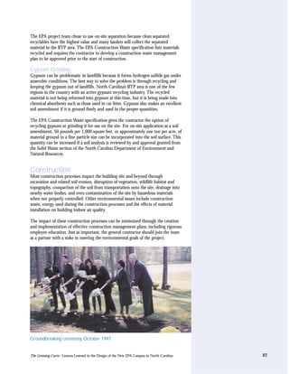


This document discusses lessons learned from designing the new U.S. Environmental Protection Agency campus in North Carolina. It aimed to minimize environmental impacts and serve as a model for sustainable design. Key challenges included balancing green goals with budget constraints and addressing sustainability holistically across site design, building systems, materials and construction practices. The project team overcame obstacles through an integrated design process, research on green strategies, and maintaining commitment to environmental stewardship.


![[Vihreä Foorumi 29.3.] Laura Varpasuo, Nokia](https://cdn.slidesharecdn.com/ss_thumbnails/nokiavihreafoorumi-120330023114-phpapp01-thumbnail.jpg?width=640&height=640&fit=bounds)


![The Humane Metropolis: People and Nature in the 21st-Century City [full text]](https://cdn.slidesharecdn.com/ss_thumbnails/fulltext-110427101308-phpapp02-thumbnail.jpg?width=640&height=640&fit=bounds)


