The document discusses the cascode amplifier, which combines the advantages of common source and common gate amplifiers by using two transistors. It offers high gain, high input impedance, and stability. The cascode arrangement is used in applications like current mirrors, modulators, and differential amplifiers. It provides concise explanations of the cascode amplifier configuration and analysis, as well as examples of cascode current mirrors and differential amplifiers.
This document provides an index of products for energy distribution networks. It includes sections on hardware, insulators, connectors, joints, terminations, and accessories for medium voltage overhead and underground networks, low voltage overhead and underground networks, and lattice towers. Each section lists the relevant part numbers and provides reference pages for more information. The index covers a wide range of equipment for electrical grid infrastructure.
This document provides an overview of voltage references and describes a lecture on bandgap voltage references. It discusses the performance requirements of voltage references including accuracy, stability, load regulation, and thermal stability. It then summarizes zener diode references and describes how a bandgap voltage reference works by combining the positive temperature coefficient of thermal voltage VT with the negative coefficient of the base-emitter voltage VBE to produce an output voltage independent of temperature. The document explains the fundamentals and shows a bandgap voltage reference circuit using two bipolar transistors with different emitter areas to generate proportional to absolute temperature (PTAT) and complementary to absolute temperature (CTAT) voltages.
Clippers and clampers are diode-based circuits used to modify signal waveforms. Clippers eliminate portions of an input signal to "clip" the waveform, and are used to remove noise or create new waveforms. They come in series and parallel types. Series clippers place the diode in series with the load, and clip voltages that don't forward bias the diode. Parallel clippers take the output across the diode, producing the voltage when it is not conducting. Clampers "clamp" a signal to a different DC level using a capacitor, diode, and resistor. The capacitor stores a reference voltage to set the output level when the diode is non-conducting.
This document contains several HSPICE examples demonstrating circuit analysis techniques, including:
1) Voltage divider, subcircuit, and calling subcircuit simulations;
2) Switching circuits using transmission line gates;
3) Pulse and triangle wave generator circuits;
4) Dependent source examples using VCCS and CCVS;
5) Ideal transformer and rectifier with filter simulations;
6) Mutual inductor, ideal op-amp, and identifying op-amp parameters;
7) Characteristic curve plotting for diode and maximum power transfer analysis.
IC Design of Power Management Circuits (IV)Claudia Sin
by Wing-Hung Ki
Integrated Power Electronics Laboratory
ECE Dept., HKUST
Clear Water Bay, Hong Kong
www.ee.ust.hk/~eeki
International Symposium on Integrated Circuits
Singapore, Dec. 14, 2009
This document summarizes key concepts about three-phase systems. It defines a three-phase system as having three sinusoidal voltages differing in phase by 120 degrees. The voltages can form a positive or negative sequence. Three-phase systems are commonly used for power generation, transmission, and distribution due to their ability to transmit more power with less material. Formulas are provided for calculating line voltages, currents, and power in balanced and unbalanced three-phase systems. Advantages of three-phase systems like constant torque and easier starting of motors are also discussed.
This document discusses symmetrical components and their application to analyzing unbalanced three-phase systems. It introduces symmetrical components as a method to represent an unbalanced system using balanced components. Specifically, it describes:
1. Representing an unbalanced three-phase system using positive, negative, and zero sequence components, which transforms the system into balanced phasors that rotate in different directions.
2. Calculating symmetrical components of voltage and current by applying transformation matrices to the phase quantities.
3. Relating line and phase quantities of voltage and current using symmetrical components. Line quantities are determined from the phase quantities.
4. Expressing complex power in an unbalanced system using symmetrical components, allowing power calculations to be
The document discusses the scattering matrix, which completely describes the behavior of a linear, multi-port microwave device at a given frequency. The scattering matrix relates the incident and reflected wave amplitudes at each port. It allows one to characterize the device using scattering parameters (S-parameters), which are the ratios of the wave amplitudes. Terminating unused ports in matched loads ensures only one incident wave is non-zero, simplifying S-parameter measurement. The scattering matrix and S-parameters provide useful information about the device and can be used to analyze microwave circuits.
The document summarizes experiments on non-linear op-amp circuits, including a comparator, half-wave rectifier, and clipper. It provides the objectives, required equipment, pre-lab questions, and theoretical explanations of how each circuit works. The experiments involve assembling the circuits using op-amps and diodes, observing input and output waveforms on an oscilloscope, and analyzing the output characteristics as circuit parameters are varied. Key points covered include how comparators detect voltage levels, how rectifiers and clippers modify input signals based on reference voltages, and the roles of op-amp gain and diode properties.
Este documento apresenta uma análise de circuitos RC, RL e RLC. Discute circuitos autônomos e com fontes constantes para cada um destes circuitos. Fornece as equações diferenciais que os descrevem e mostra como resolver estas equações para obter as soluções para a tensão ou corrente nos elementos armazenadores de energia.
O documento apresenta um capítulo sobre circuitos RC em corrente alternada. Nele, são resolvidos diversos exercícios que envolvem o cálculo de impedâncias, correntes, tensões e outros parâmetros desses circuitos, utilizando fórmulas como a lei de Ohm complexa.
Mesh analysis is a technique for analyzing electrical circuits using loops or meshes. It involves assigning a mesh current to each loop and writing Kirchhoff's voltage law equations for each mesh. The mesh equations take the form of a matrix equation that can be solved for the unknown mesh currents. Key aspects of mesh analysis include defining mesh currents, writing KVL equations clockwise around each mesh, identifying common resistance terms between meshes, and handling circuits with current sources by removing the source and including it as a constraint.
IC Design of Power Management Circuits (I)Claudia Sin
by Wing-Hung Ki
Integrated Power Electronics Laboratory
ECE Dept., HKUST
Clear Water Bay, Hong Kong
www.ee.ust.hk/~eeki
International Symposium on Integrated Circuits
Singapore, Dec. 14, 2009
Small signal analysis of bjt amplifiersPRAVEENA N G
The document summarizes small signal analysis of various BJT amplifier configurations. It discusses the hybrid-pi model of the BJT with and without Early effect. It then analyzes the common emitter amplifier without and with load resistance RE. It also analyzes the common collector (emitter follower) and common base amplifiers. Key parameters discussed include input resistance Ri, output resistance Ro, voltage gain AV, and current gain AI. Circuit analysis uses the hybrid-pi model and applies voltage and current division rules.
The document summarizes an electrical engineering experiment on diode applications. It discusses (1) three main types of rectifier circuits - half-wave, center tap full-wave, and full-wave bridge rectifiers, (2) the theory and circuit diagrams of each type, and (3) the results of building and testing each circuit. It also covers (4) diode clipping and clamping circuits, explaining their principles of operation and providing circuit diagrams and test results. Overall, the experiment demonstrated how diodes can convert AC to DC and be used in clipping and clamping applications.
The presentation describes diode application; series / parallel diode configuration, half wave and full wave rectifier, clipper, clamper, zener diode as a shunt regulator, voltage multiplier
Mechanics Of Materials 9th Edition Hibbeler Solutions ManualVictoriasses
- A tension test was performed on a steel specimen with an original diameter of 0.503 in. and gauge length of 2.00 in.
- The stress-strain diagram was plotted from the provided data and the modulus of elasticity, yield stress, ultimate stress, and rupture stress were determined.
- The modulus of elasticity was approximated to be 32.0(103) ksi, the yield stress was approximated to be 55 ksi, the ultimate stress was approximated to be 110 ksi, and the rupture stress was approximated to be 93.1 ksi.
The document provides extensive technical information about the EPT3600-14B circuit board used in many CB radio models manufactured by Uniden, including the Alan 8001. It describes the origins and versatility of the circuit board, lists over 50 radio models that use it, and provides detailed specifications, diagrams, documentation and procedures for alignment of the Alan 8001. The document aims to make comprehensive information available in Portuguese for amateur radio operators interested in using and experimenting with radios containing the EPT3600-14B board.
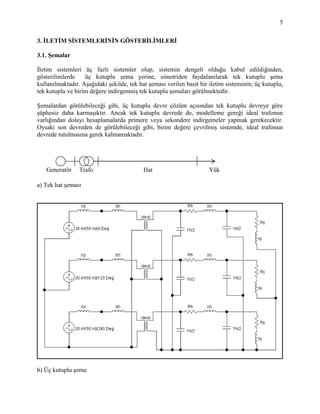
1. 5
3. İLETİM SİSTEMLERİNİN GÖSTERİLİMLERİ
3.1. Şemalar
İletim sistemleri üç fazlı sistemler olup, sistemin dengeli olduğu kabul edildiğinden,
gösterilimlerde üç kutuplu şema yerine, simetriden faydalanılarak tek kutuplu şema
kullanılmaktadır. Aşağıdaki şekilde, tek hat şeması verilen basit bir iletim sisteminin; üç kutuplu,
tek kutuplu ve birim değere indirgenmiş tek kutuplu şemaları görülmektedir.
Şemalardan görülebileceği gibi, üç kutuplu devre çözüm açısından tek kutuplu devreye göre
şüphesiz daha karmaşıktır. Ancak tek kutuplu devrede de, modelleme gereği ideal trafonun
varlığından dolayı hesaplamalarda primere veya sekondere indirgemeler yapmak gerekecektir.
Oysaki son devreden de görülebileceği gibi, birim değere çevrilmiş sistemde, ideal trafonun
devrede tutulmasına gerek kalmamaktadır.
a) Tek hat şeması
b) Üç kutuplu şema
Generatör Trafo Hat Yük
2. 6
c) Tek kutuplu şema
d) Tek kutuplu şema (birim değere indirgenmiş sistem)
Şekil 3.1 Basit bir iletim sisteminin gösterilimleri
3.2. Birim Değerler
Enerji iletim sistemlerinin incelenmesinde, sistemdeki elemanların (generatör, trafo, hat, yük, ...)
birim (pu : per-unit) değerlerinin elde edilmesi büyük kolaylıklar sağlar. Bu amaçla aşağıdaki
algoritma kullanılabilir :
1.Adım: Baz Seçimi: Güç (S), Gerilim (U), Akım (I), Empedans (Z),....büyüklüklerinden
herhangi ikisi baz seçilir. (geleneksel olarak SBAZ ve UBAZ alınır)
2.Adım: Diğer büyüklüklerin baz değerleri, bilinen formüller yardımıyla hesaplanır.
BBB U.3/SI , B
2
BB S/UZ , . . .
3.Adım: Bir elemanın
DegerBaz
DegerGerçek
DegeriBirim şeklinde belirlenir.
3. 7
Generatör Trafo 1 İletim Hattı ( L km) Trafo2 Yük
Güç Sg St1 St2 Syük
Gerilim Ug U1 / U2 U2 / U3 Uyük
Empedans Xd Xt1 Zhat Xt1
BAZ (Üretim) (İletim) (Yük)
Güç SBAZ SBAZ SBAZ
Gerilim UBAZ = U1 UBAZ = U2 UBAZ = U3
Akım 1BAZ U.3/S 2BAZ U.3/S 3BAZ U.3/S
Empedans
BAZ
2
1 S/U BAZ
2
2 S/U BAZ
2
3 S/U
Transformatörlerden dolayı, baz gerilimi de trafoların anma çevirme oranlarında tam olarak
dönüştürürler. Ancak seçilen baz gerilimi hat geriliminden farklı ise (UBAZ U2), baz geriliminin
yine trafonun anma çevirme oranlarına göre çevrilmesi gerekecektir, bu durumda baz gerilimi
dağılımı ;
Gerilim (U1/U2)*UBAZ UBAZ (U3/U2)*UBAZ
şeklinde olmalıdır. Eğer, örnekteki ikinci trafonun çevirme oranı, U3 yüksek gerilim tarafı olmak
üzere (U3/U4) ise baz gerilimi dağılımı;
Gerilim (U1/U2)*UBAZ UBAZ (U4/U3)*UBAZ
şeklinde olacaktır.
Örnek 1 :
Generatör Trafo 1 İletim Hattı Trafo2 Yük
Gerilim(kV) 20 20 / 380 380 / 36 36
BAZ (Üretim) (İletim) (Yük)
Gerilim(kV) 20 380 36
3 ~
3 ~
4. 8
Örnek 2 :
Generatör Trafo 1 İletim Hattı Trafo2 Yük
Gerilim(kV) 20 20 / 380 380 / 36 36
BAZ (Üretim) (İletim) (Yük)
Gerilim(kV) (20/380)x400 = 21 400 (36/380)x400=38
Örnek 3 :
Generatör Trafo 1 İletim Hattı Trafo2 Yük
Gerilim(kV) 20 20 / 400 360 / 36 36
BAZ (Üretim) (İletim) (Yük)
Gerilim(kV) (20/400)x380 = 19 380 (36/360)x380=38
3.2.1. Tek ve Üç Fazlı Devreler İçin Empedansın Baz Değeri
Tek fazlı devrelerde;
BBB I.ZV , BBB I/VZ , BBB I.VS , BBB V/SI ifadelerinden tek fazlı devreler
için empedans değeri;
B
2
BB S/VZ VB : Faz Nötr Gerilimi (1)
olarak bulunur.
Üç fazlı devrelerde ise; (3 3Faz anlamında bir indis)
3BB S
3
1
S , 3/UV BB ifadelerini (1) de yerine koyarak;
3/S/3/UZ 3B
2
BB
3B
2
BB S/UZ UB : Faz Arası Gerilimi (2)
olarak empedans değeri bulunur.
3 ~
3 ~
5. 9
3.2.2. Sistemde Baz Değişimi
İletim sisteminde bulunan generatör, transformatör, büyük güçlü motorlar gibi elektriksel
cihazların empedansları genellikle “ohm” olarak değil, bu cihazların kendi anma gerilim ve anma
güçleri cinsinden “birim değer – pü” olarak verilir. Bu cihazların baz değerleri, kullanıldıkları bir
sistemde seçilen baz değerinden farklı olabilir. Yada yukarıda bahsedildiği gibi
transformatörlerin çevirme oranlarında dolayı yalnızca baz gerilim değişebilmektedir. Dolayısı
ile, gerekli baz dönüşümleri yapılarak bu cihazların empedanslarına ilişkin “yeni bir birim değer”
hesaplanmalıdır.
Bpü Z/ZZ , B
2
BB S/UZ , 2
B
B
pü
U
S
ZZ
0
2
B
0B
püo
U
S
ZZ ,
n
2
B
nB
pün
U
S
ZZ
Zpüo : empedansın eski birim değerini, Zpün : empedansın yeni birim değerini ifade etmektedir.
Bo
Bn
2
Bn
Bo
0püpün
S
S
V
V
ZZ (3)
(3) ifadesinde VBo ve SBo sırasıyla eski baz gerilimi ve baz gücü , VBn ve SBn sırasıyla yeni baz
gerilimi ve baz gücü temsil etmektedir.
3.2.3. Birim Değerlerin Faydaları
Tüm bara gerilimleri "1 pü" civarında olur ve birbirleri ile kıyaslamaları kolaylaşır,
Transformatörlerin çevirme oranlarından kurtulunur,
Transformatörlerin oluşturduğu kuplajlı çevre sayısı azalır,
Ancak faz kaydırıcılı ve kademe değiştiricili trafolar için model irdelenmelidir.
6. 10
3.3. Sistem Elemanlarının Modelleri
3.3.1. Generatör
Generatörler en basit model olarak sürekli hal incelemelerinde, sargı direnci ihmal edilerek sabit
bir reaktans (Xd : Senkron Reaktans) gerisinde bir EMK ile modellenirler. Bunun yanında
transiyent (geçici hal) subtransiyent (üst geçici hal) durumlarında E ve Xd farklı değerler alır.
Durum EMK Reaktans
Sürekli-Hal E Xd
Geçici Hal E' Xd'
Üst Geçici Hal E'' Xd''
Genellikle; E'' > E' > E ve Xd'' < Xd' < Xd
S ve U sırasıyla generatörün, anma gücü ve anma gerilimidir.
Xd kendi güç ve gerilim BAZ olmak üzere pu veya % olarak verilir.
Örnek :
S=50 MVA, U = 15 kV Xd = 0,25 pu verilerine göre Xd nin gerçek değerini hesaplayınız.
Bir büyüklüğün birim değeri için kullanılan ifadeye göre;
)Xd(Baz
)Xd(Gerçek
pu)Xd( olacaktır
Xd nin baz değeri ise generatörün kendi U ve S değerleri baz kabul edilerek belirlenebilir.
BAZ
2
BAZ
BAZ
S
U
)Xd(
Xd nin gerçek değeri
125,15,4x25,0
50
225
25,0
50
15
25,0
S
U
25,0)X()X(X
22
BAZdpudd
Örnek :
Aynı generatörün, SBAZ=100 MVA UBAZ = 16 kV olan bir sisteme bağlı olması durumunda
Xd nin yeni birim değerini hesaplayınız.
7. 11
pu4395,029375,025,0
50
100
16
15
25,0
S
S
U
U
)X()X( 2
2
BO
BN
2
BN
BO
pudOpudN
3.3.2. Trafolar
1
2
2
1
2
1
I
I
U
U
N
N
n
2t
2
2
1t
2
1
2211
X
U
X
U
IUIUSt
2
2
2
2
1
2t
1t
n
U
U
X
X
2t
2
1t XnX
2
1t
2t
n
X
X
(1) Primerden (2) Sekondere (2) Sekonderden (1) Primere
U 1/n n
I n 1/n
Z 1/n2
n2
SBAZ = St
1BAZ UU
St
U
Z
2
1
1BAZ
1BAZ
1t
put
Z
X
X
2BAZ
2t
1BAZ
1t
put
Z
X
Z
X
X
2BAZ UU
St
U
Z
2
2
2BAZ
2BAZ
2t
put
Z
X
X
İspat :
StU
X
StU
X
X tt
put 2
2
2
2
1
1
2
2
2t
2
1
1t
put
U
X
U
X
X 2
2
2t
2
2
2t
2
2
1
1t
put
U
X
)Un(
Xn
U
X
X
2
2
2
1
2
1
U
U
X
X
t
t
8. 12
15 / 154 kV
St= 250 MVA
Xt=0,1 pu
UBAZ=154 kV SBAZ = 100 MVA olması durumunda Xt nin yeni birim değeri ?
primer UBAZ=154 kV olduğuna göre,
sekonder kV44,14
160
15
154UBAZ
3.3.3. Yükler
Büyük güçlerdeki motorlar, senkron generatöre benzer biçimde, bir
EMK önünde reaktansla modellenirler ( U > E ) modunda çalışma olur.
Diğer yükler genellikle pasif empedans (admitansla) modellenirler
YÜK
YÜK
YÜK
S
U
Z
2
YÜK
YÜK
YÜK
S
I
3 U
BAZYÜK
YÜK
puYÜK
I
I
I
BAZ
YÜK
YÜK
Z
Z
Z
).( jSinCosII puYÜKpuYÜK ).( jSinCosZZ puYÜKpuYÜK
pu04,0
250
100
154
154
1,0X
2
punt
pu04,0
250
100
15
15
1,0X
2
punt
pu043,0
250
100
154
160
1,0X
2
punt
pu043,0
250
100
44,14
15
1,0X
2
punt
15 / 160 kV
St= 250 MVA
Xt=0,1 pu