Download to read offline
![International Research Journal of Engineering and Technology (IRJET) e-ISSN: 2395-0056
Volume: 04 Issue: 09 | Sep -2017 www.irjet.net p-ISSN: 2395-0072
© 2017, IRJET | Impact Factor value: 5.181 | ISO 9001:2008 Certified Journal | Page 110
Energy Absorption Characteristics of Thin Walled Metallic and Foam
Filled Tubular Structure with Different Cross-Sections
Chinmay Morajkar
Master of Technology, Machine Design
Student of Mechanical Engineering Department, UBDTCE Davangere, Karnataka, India
---------------------------------------------------------------------***---------------------------------------------------------------------
Abstract – The thin –walled structures are been used widely
as energy absorbers in industries such as aerospace, shipping
and automobile. The energy absorption behavior of tubular
structures depends on various factors in which one of them is
cross sectional geometry of tube structures .In this paper
Metallic tubular structures and foam filled metallic tubular
structures with different cross sections are studied. The
tubular structures with different sections such as circular,
hexagonal, triangular and square are studied based on the
energy absorption point of view. The tubes have the same
height, average section area, volume, thickness and material
which are subjected to quasi static loading. Theeffectof foam
has been studied during the crushing process since foam can
be used for different crash analysis problem. The numerical
model has been modeled and meshed using hyper mesh and
analyzed using commercial explicit finite element solver Ls-
Dyna. Finally the metallic and foam filled metallic tubes
analysis results are being compared based on the energy
absorption point of view.
Key Words: Specific Energy Absorption, Crushing Load,
Piecewise Linear Plastic, Crushable Foam, Quasi Static
Process.
1. INTRODUCTION
Safety of the passenger and driver has become an issue
almost from the beginning of mechanized road vehicle
development. Vehicle is used extensivelyanda largenumber
of safety accidents related to them occur widely. Using
energy absorbers is an appropriate option for this purpose.
As an energy absorber in crashworthiness applicationssuch
as cars, ships, trains, aero-planes and other high-volume
industrial products, the thin-walled structures have been
widely used to ensure crash safety due to their lightweight,
low cost and high energy absorption.
Tubular structures provide widest range of possible energy
absorbing system for any simplestructures.Apartfromtheir
use as energy absorbers, their common existence as
structural elements implies an in strict energy absorbing
capability in the largest part of the aerospace and
automobile structures.
Metallic foams is being used in aerospace industry in
different components to absorb the energyofanimpactorin
shielding devices to reduce the shock wave from a blast
which might also have complex shapes, Aluminum, nickel,
iron, copper, titanium and platinumaresomeofthecommon
metals which are used to prepare metallic foams.
In this paper, energy absorption capacity of thin walled
metallic and foam filled metallic tubes with various section
geometries are investigated and studied numerically.
1.1 LITERATURE SURVEY
In order to carry out the entitled work an extensive
literature survey was done by collecting and studying the
number of relevant journals, articles and technical papers
from the available resources.
Tubular structures are been used as energy absorbers in
various aerospace and automobile applications. Tubular
structures providehighspecificenergyabsorptioncapability
as well as light weight advantage. So it becomes an
important part to study the tubular structureswithdifferent
shapes. The effect of various cell configuration on energy
absorption behavior of tubular structures were carried out
by the different researchers,thenumerical andexperimental
correlation was given by Ali Alavi Nia et.al [1] andnumerical
examination was carried out by Younes et.al [2] for thin
walled tubes with various section shapes by maintaining
same mass for each case and found that the circular tubes
has the most energy absorption capacity [1] and the energy
absorption capability of tubular structure increases with
increase in number of sides [2]. The study is carried out by
using foam filled tubular structure which shows better
results compared to metallic structures as well asduringout
of planes impacting condition along with the cell geometry
the cell foil thickness, cell side size, cell expanding anglealso
affects the energy absorption capacitytubularstructures[3].
Alexander et.al [4] accomplished the first studies on the
collapse mode of cylindrical tubes under axial loads. The
theoretical model for collapse of steel conical tubes based on
experimental observation was done by Al-Hassani et.al [5]
and Mamalis et.al [6]. The average crushing load of square
tubes under axial static loads was studied experimentallyby
Abramowiz and Jones et.al [7]. They also carried out several
experiments on circular and square tubes under dynamic
loading conditions and presented a modification of
Alexander’s theoretical model.](https://image.slidesharecdn.com/irjet-v4i922-170927093120/75/Energy-Absorption-Characteristics-of-Thin-Walled-Metallic-and-Foam-Filled-Tubular-Structure-with-Different-Cross-Sections-1-2048.jpg)
![International Research Journal of Engineering and Technology (IRJET) e-ISSN: 2395-0056
Volume: 04 Issue: 09 | Sep -2017 www.irjet.net p-ISSN: 2395-0072
© 2017, IRJET | Impact Factor value: 5.181 | ISO 9001:2008 Certified Journal | Page 111
In spite of the much research performed on circular thin-
walled tubes, the attempt to further improve the crushing
behavior of thin walled tubes by designing an efficient
energy absorbing material is highly desired. This numerical
study aims to improve the energy absorbing capacity of the
thin-walled tubes subjected to axial quasi static loading.
1.2 METHODOLOGY
In order to understand the crushing behavior of the tubular
structures based on energy absorbing characteristics during
impact event, the methodology is adopted. Based on the
study of available literaturetheprocessofenergyabsorption
behavior of thin walled structures is examined. In order to
correlate the numerical analysis the impact study has been
carried out on the thin walled structures of metallic as well
as foam filled structures by applyingtheloadonthedifferent
geometries cross section. For this case the modeling of the
tubular structure is done by using the available modeling
and meshing tool HYPERMESH V12.0. Then the analysis is
carried out by importing the model to available solver tool
LS DYNA 971 R 8.0 solver.
2. FINITE ELEMENT ANALYSIS
The Finite Element model consists of tubular structure and
two rigid blocks, the tube structures are made up of shell
elements and two rigid blocks are taken as solid elements.
Modelling is carried out in HYPERMESH and analysis is
carried out using LS DYNA.
The geometric model considered for theanalysisisasshown
in Fig-1 and it consists of Lower block and upper block
which are movable and fixed respectively, In between a
tubular structure is present which is of 100mm length. The
meshed model considered for the analysisisasshowninFig-
2.
Fig-1 Geometric model of tubular structure
All the tubular sections are having same length, average
section area and volume, the specifications of these are as
shown in Table-1.
Table -1: Specification of tubular structure
Fig-2 Meshed model of tubular structure
3. BOUNDRY AND LOADING CONDITIONS
The model geometry includes thin walled tubular structure
with metallic and foam filled tube between two rigidparts at
sits ends. The boundary conditions are the same as the
experimental test conducted by the reference [1] the upper
block is completely constrained in all directionswhereasthe
lower block can move with a velocity of 100mm/s in the
upward direction.
4. MATERIAL PROPERTIES
The material model for the tube, foam and blocks are
*MAT_PIECEWISE_LINEAR_PLASTICITY,
*MAT_CRUSHABLE_FOAM and *MAT_RIGID, respectively.
The material used for the metallic tube structure is Al3003
and foam is of carbon Nano. The material properties of
Al3003 tube are tabulated in Table-2.
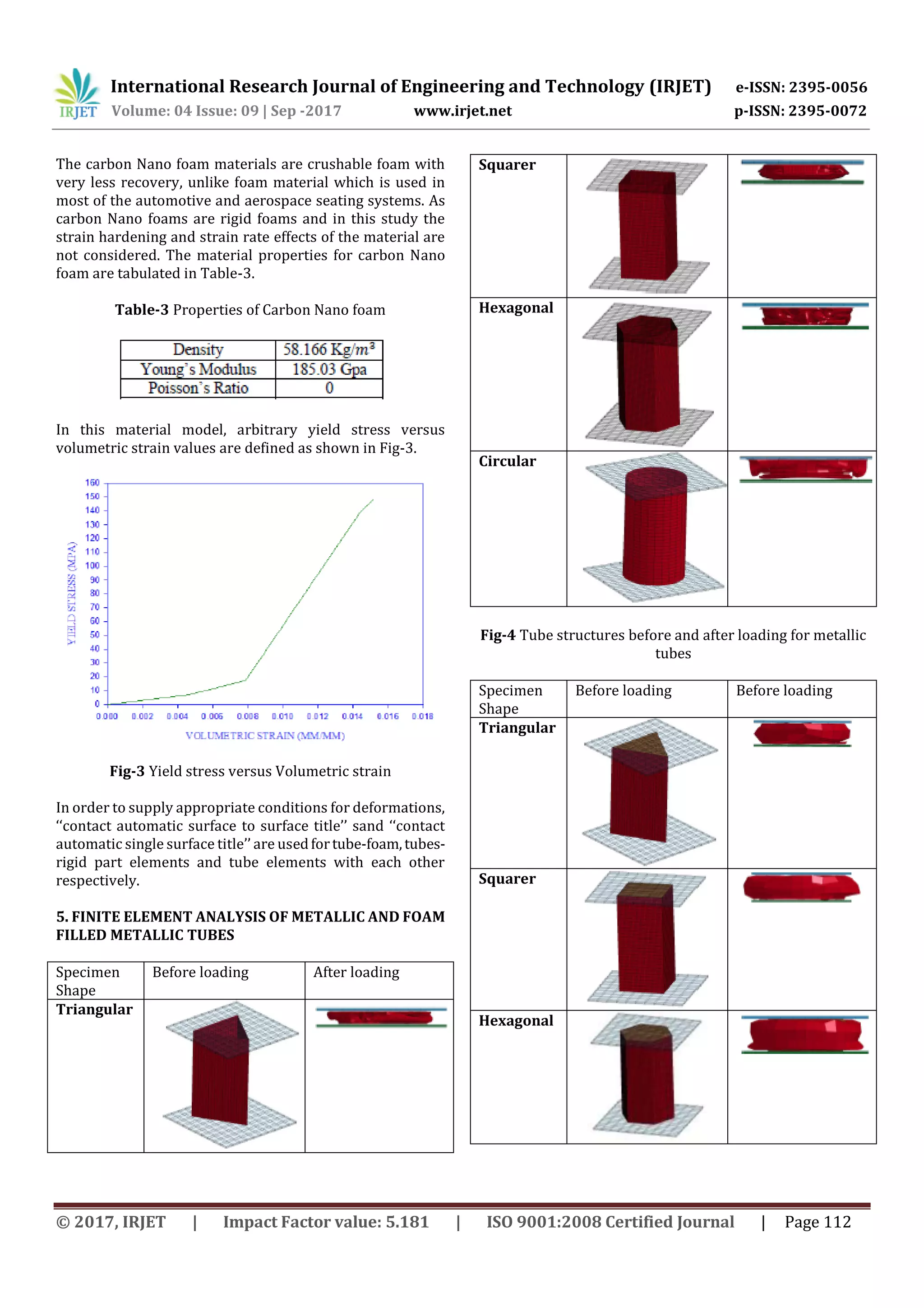
Table-2 Properties of Al3003](https://image.slidesharecdn.com/irjet-v4i922-170927093120/75/Energy-Absorption-Characteristics-of-Thin-Walled-Metallic-and-Foam-Filled-Tubular-Structure-with-Different-Cross-Sections-2-2048.jpg)

This document discusses a numerical study comparing the energy absorption characteristics of thin-walled metallic tubular structures with different cross-sectional geometries, both empty and foam-filled. Finite element models of circular, triangular, hexagonal and square tubes undergoing quasi-static axial crushing were created and analyzed. The results show that circular tubes absorbed the most energy of the empty metallic tubes, while foam-filled tubes had higher energy absorption than empty tubes of the same geometry.


