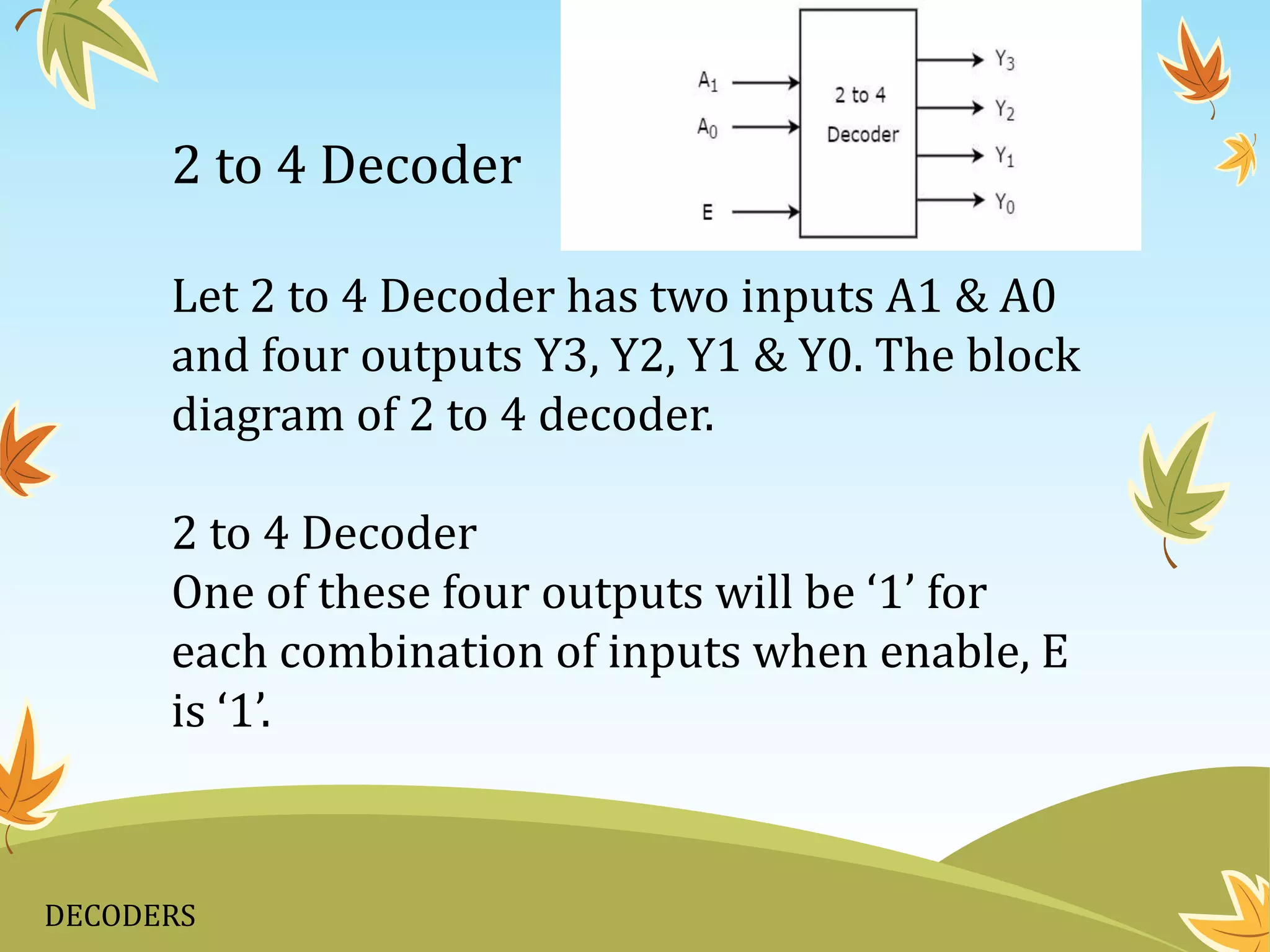
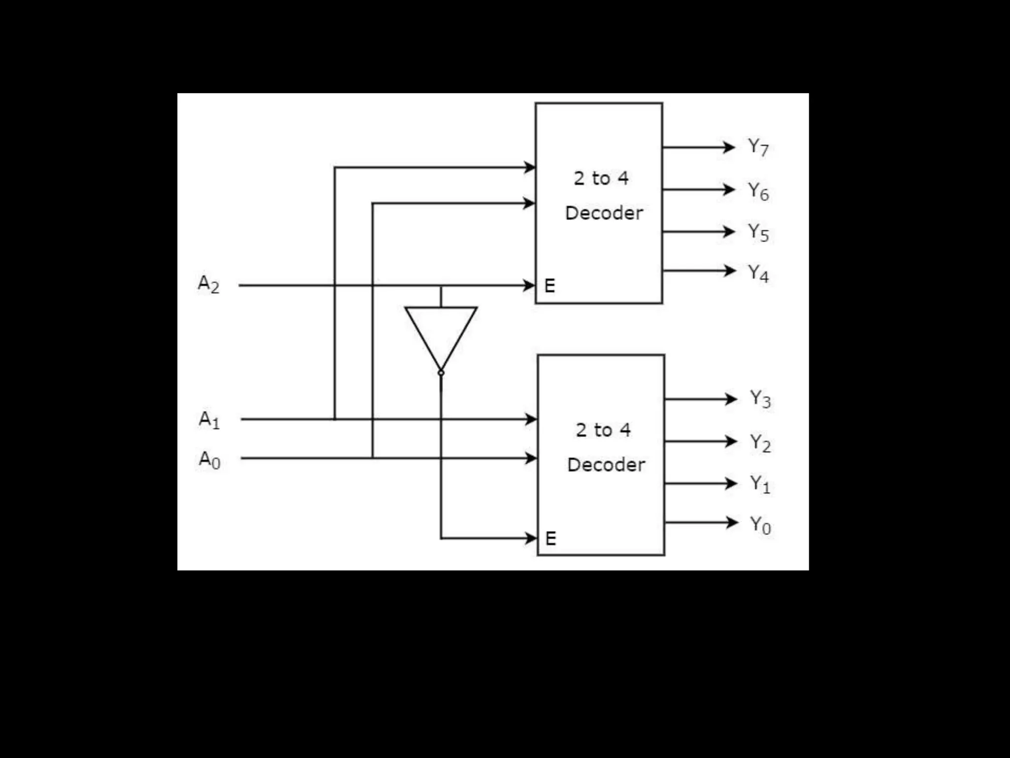
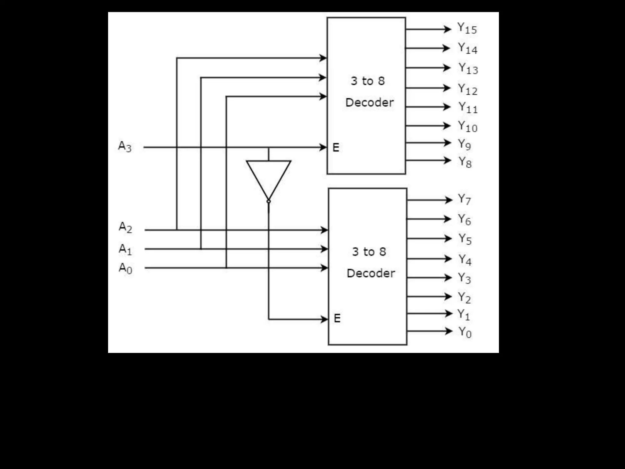
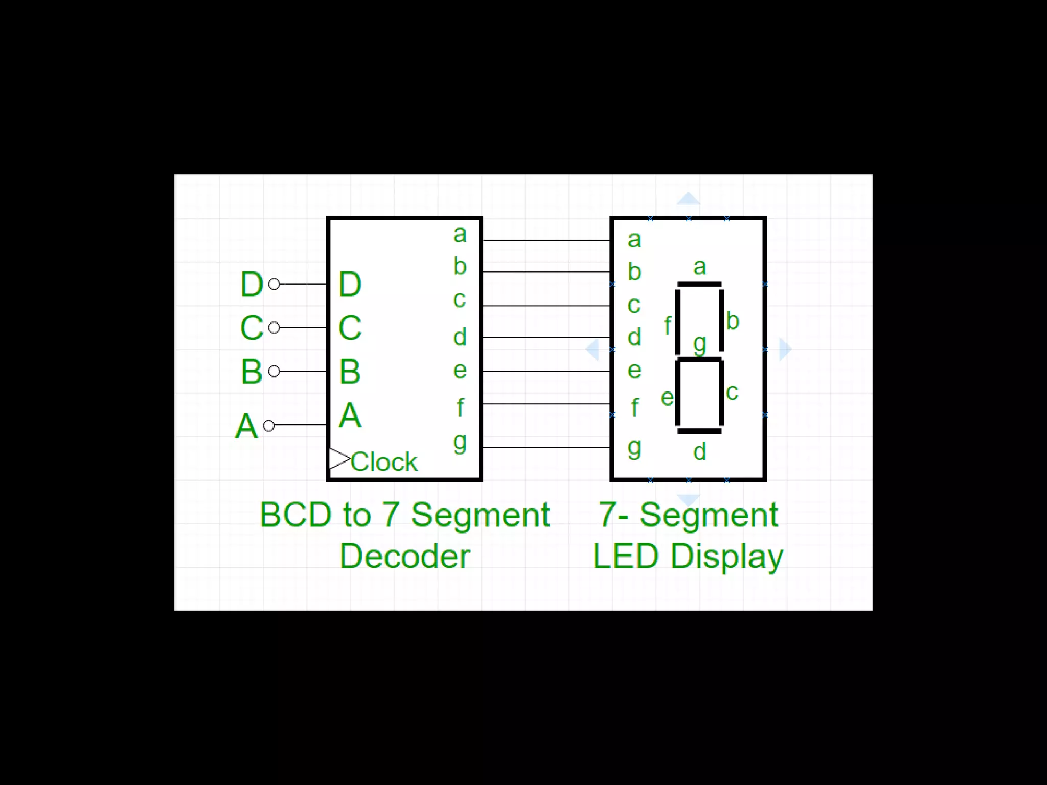
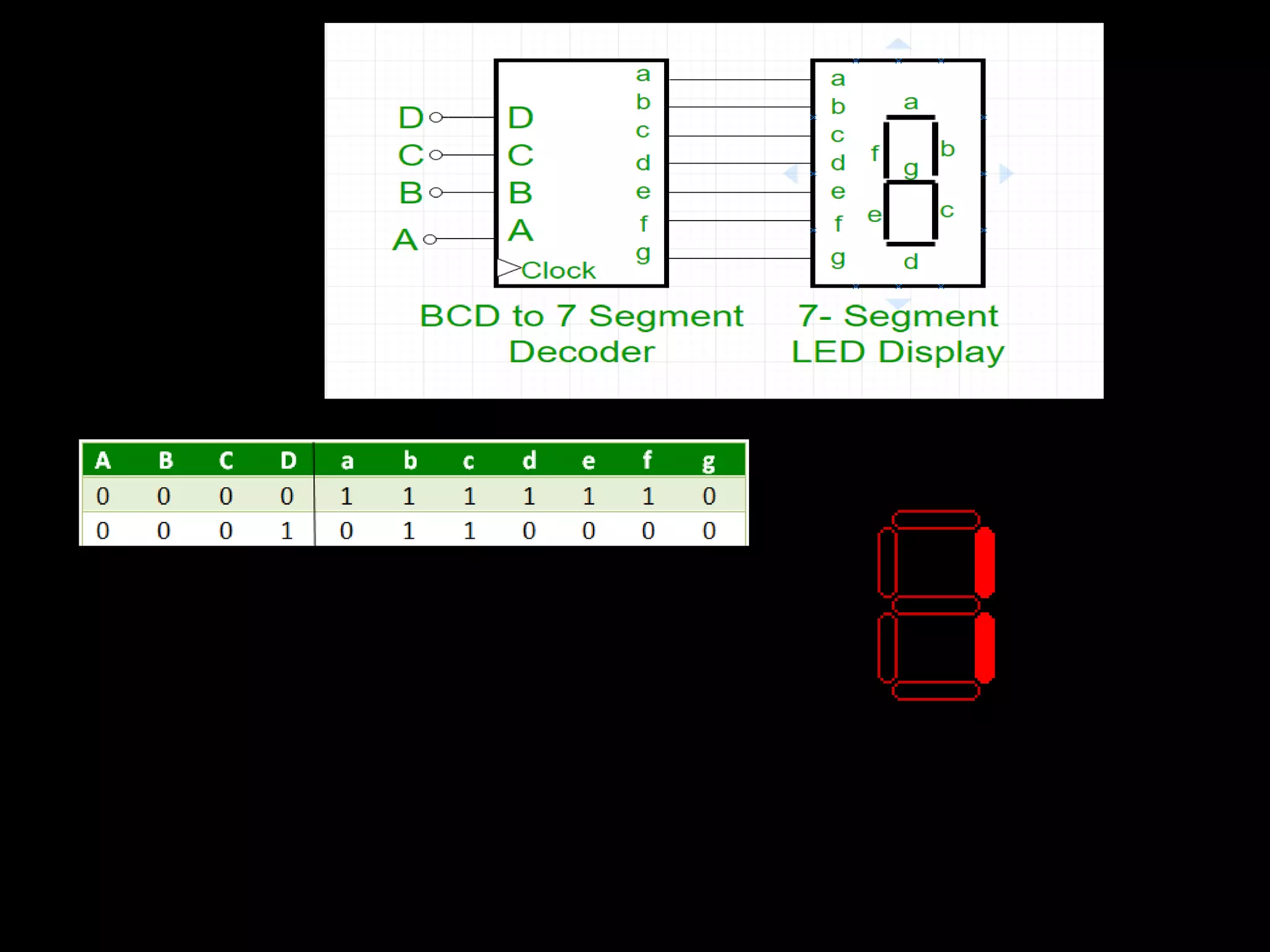
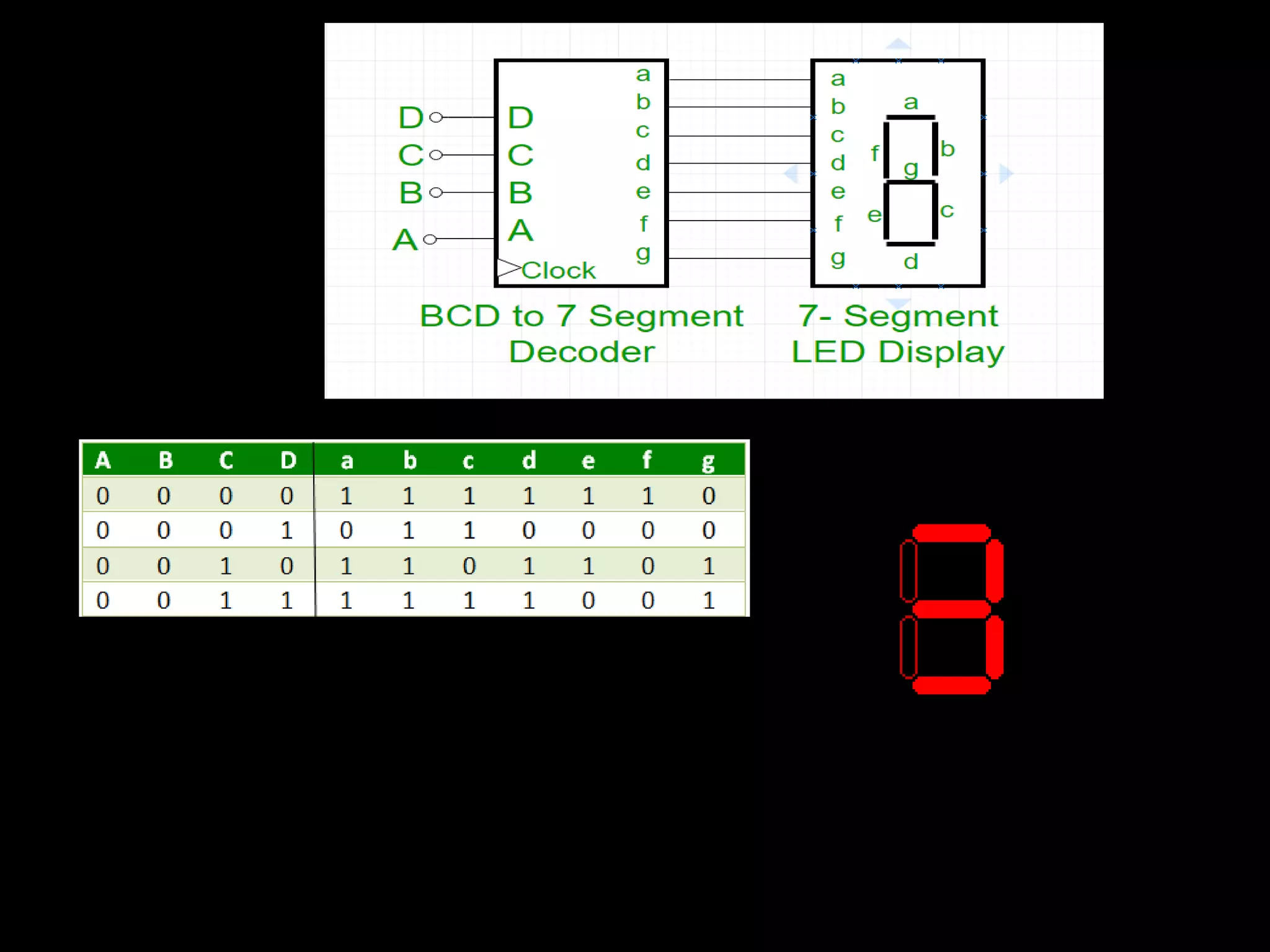
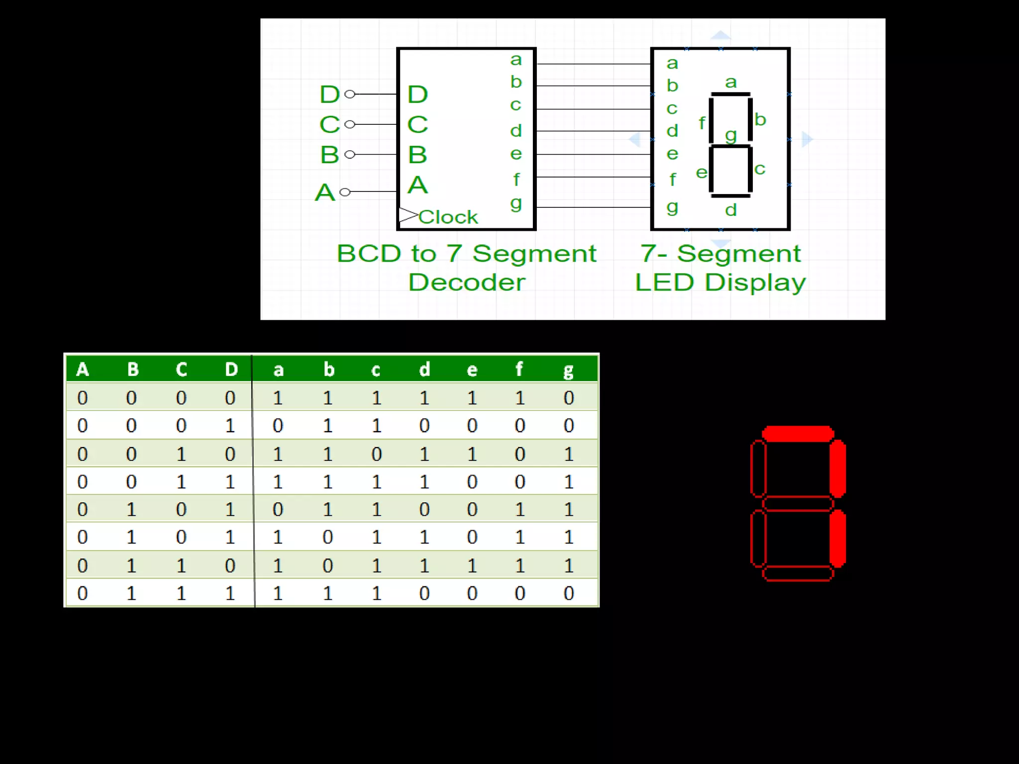
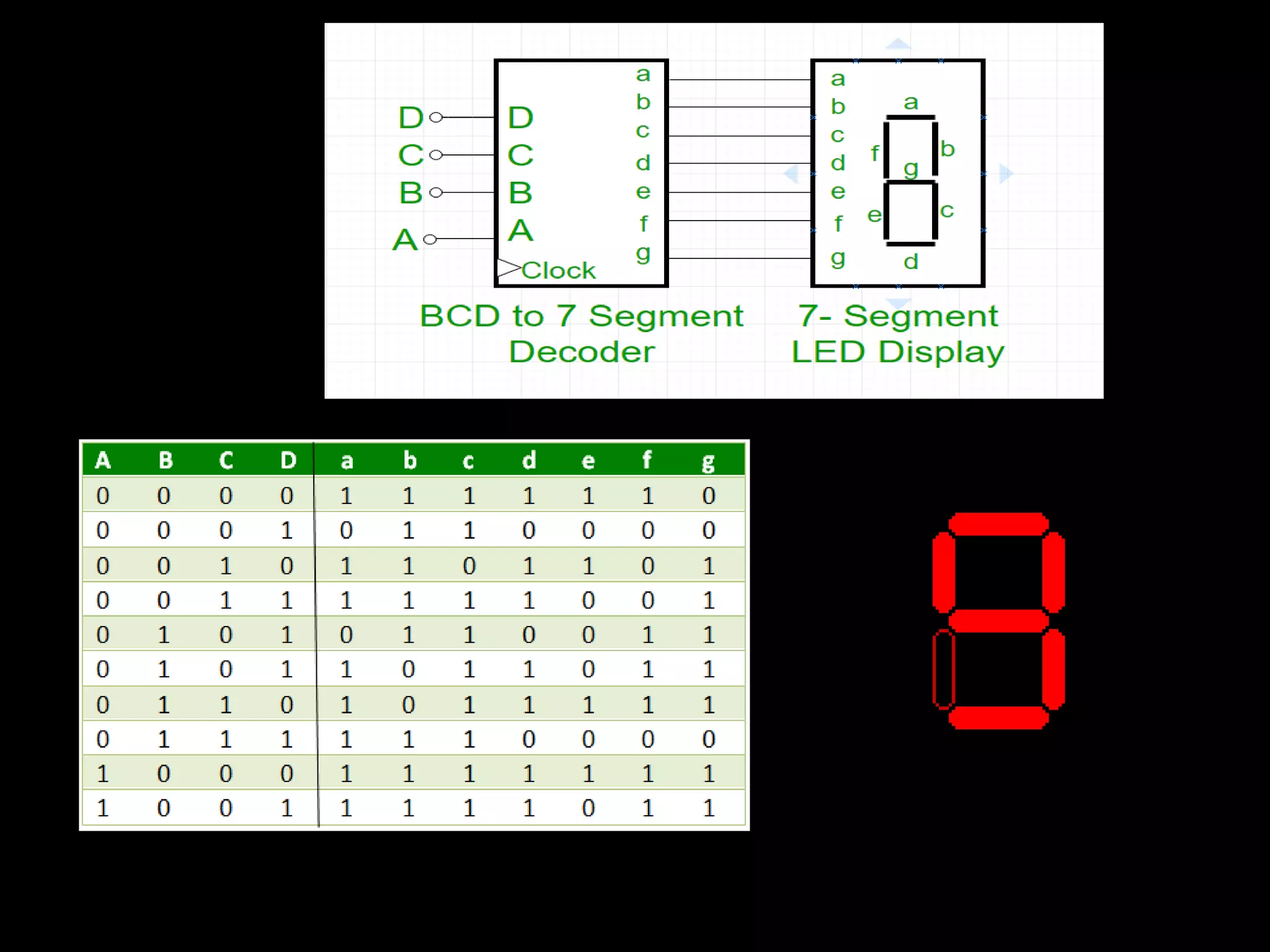
2. DECODERS
1. What is Decoders………….?
2. Type of decoders
3. 7 – SEGMENT DISPLAY USING DECODERS
3. DECODERS
A decoder is a circuit that
changes a code into a set of
signals. It is called a decoder
because it does the reverse of
encoding, but we will begin our
study of encoders and decoders
with decoders because they are
simpler to design.
4. DECODERS
Decoder is a combinational circuit that
has ‘n’ input lines and maximum of 2n
output lines. One of these outputs will
be active High based on the combination
of inputs present, when the decoder is
enabled. That means decoder detects a
particular code. The outputs of the
decoder are nothing but the min terms
of ‘n’ input variables (lines), when it is
enabled.
6. DECODERS
2 to 4 Decoder
Let 2 to 4 Decoder has two inputs A1 & A0
and four outputs Y3, Y2, Y1 & Y0. The block
diagram of 2 to 4 decoder.
2 to 4 Decoder
One of these four outputs will be ‘1’ for
each combination of inputs when enable, E
is ‘1’.
9. DECODERS
3 to 8 Decoder
In this section, let us implement 3 to 8 decoder using 2 to 4
decoders. We know that 2 to 4 Decoder has two inputs, A1 & A
and four outputs, Y3 to Y0. Whereas, 3 to 8 Decoder has three
inputs A2, A1 & A0 and eight outputs, Y7 to Y0.
Required number of lowero rderdecoders=m2/m1
Where,
m1 is the number of outputs of lower order decoder.
m2 is the number of outputs of higher order decoder.
Here, m1 = 4 and m2 = 8. Substitute, these two values in the
above formula.
Requirednumberof 2to4decoders=8/4=2
12. DECODERS
BCD to 7 Segment Decoder
In Binary Coded Decimal (BCD) encoding scheme
each of the decimal numbers(0-9) is represented by
its equivalent binary pattern(which is generally of
4-bits).
Whereas, Seven segment display is an electronic
device which consists of seven Light Emitting
Diodes (LEDs) arranged in a some definite pattern
(common cathode or common anode type), which is
used to display Hexadecimal numerals(in this case
decimal numbers,as input is BCD i.e., 0-9).