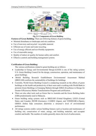
The document serves as a learning manual for a course titled 'Emerging Trends in Civil Engineering' under the Maharashtra State Board of Technical Education. It emphasizes the importance of updating the civil engineering curriculum in line with rapid technological advancements and industry demands, providing details on course outcomes, teaching guidelines, and recommended software. Additionally, it outlines key topics such as soft computing techniques, sustainable resource management, and advanced construction materials.

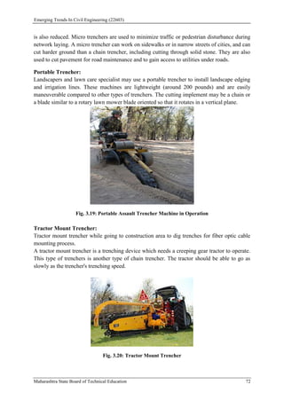
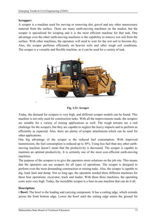
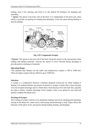
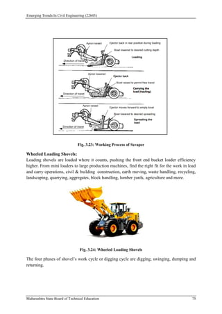
![Emerging Trends In Civil Engineering (22603)
Maharashtra State Board of Technical Education 149
recommended now a day’s except in places where it is already available as inherent energy in
waste products and in landfills. However use of geothermal piles as heating systems is
prevalent in places like UK.
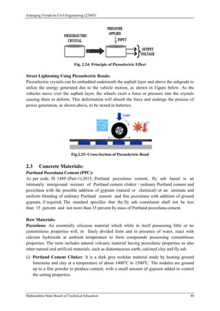
Methods of Heating Soil In-Situ:
Ground surface heating
Heating through boreholes
Use of thermally stabilized building blocks
Thermal piles
Geothermal piles are an innovative system of building foundations for use in combination
with ground-source energy technology. Conventional ground-loops are installed in building
piles, through which water or another fluid is pumped. The fluid and ground-transfer heat
energy is then passed through a heat exchanger in the building to provide cooling or, more
commonly, heating in the winter. The geothermal system is essentially the same as closed-
loop borehole systems; however, since they are installed in the building foundations, the
technology serves a dual purpose.
Soil Freezing:
Soil freezing involves lowering the temperature of the soil until the moisture in the pore
spaces freezes. Freezing of pore water acts as a cementing agent between the soil particles
causing significant increase in shear strength and permeability. Unlike soil heating, soil
freezing may be applicable to a wide range of soil types, grain sizes and ground conditions.
Fundamentally, the only requirement is that the ground has sufficient soil moisture (pore
water) [26]. The process typically involves installing double walled pipes in the soil. A
coolant is circulated through a closed circuit. A refrigeration plant is used to maintain the
coolant’s temperature.
It is applicable to a wide range of soils but it takes considerable time to establish a substantial
ice wall and the freeze must be maintained by continued refrigeration as long as required. It
may be used in any soil or rock formation regardless of structure, grain size or permeability.
However, it is best suited for soft ground rather than rock conditions. Freezing may be used
for any size, shape or depth of excavation and the same cooling plant can be used from job to
job. As the impervious frozen earth barrier is constructed prior to excavation, it generally
eliminates the need for compressed air, dewatering, or the concern for ground collapse during
dewatering or excavation.
Applications:
Temporary underpinning of adjacent structure and support during permanent
underpinning.
Shaft sinking through water-bearing ground.
Shaft construction totally within non-cohesive saturated ground.
Tunnelling through a full face of granular soil.](https://image.slidesharecdn.com/22603-230224032204-86959fb0/85/Emerging-Trends-in-Civil-Engineering-22603-pdf-160-320.jpg)