eMBMS - the future of
Multimedia Broadcasting?
By: Isybel Harto
What is eMBMS
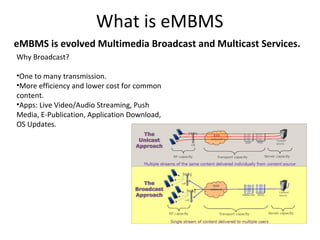
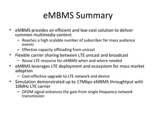
eMBMS is evolved Multimedia Broadcast and Multicast Services.
Why Broadcast?
•One to many transmission.
•More efficiency and lower cost for common
content.
•Apps: Live Video/Audio Streaming, Push
Media, E-Publication, Application Download,
OS Updates.
Support in LTE (E-UTRAN) over Single
Frequency Network (MBSFN)
1.

2.

3.

Simulcast transmission technique
realised by transmission of identical
waveforms at the same time from
multiple cells.
An MBSFN transmission from multiple
cells within an MBSFN Area is seen as a
single transmission by a UE.
MBSFN reception is possible in
connected and idle states independent
of incoming or outgoing calls
Multimedia Broadcast over Single
Frequency Network (MBSFN)
MBMS Are Planning
MBMS service area (1/2)

• eNBs transmitting MBSFN are required to be synchronised in
time
• Overlap between MBSFN areas is supported

• One cell can belong to several MBSFN areas (up to 8 MCCHs)
• An MBMS capable UE is required to receive the signal of at least one of
the MBSFN areas

• Reserved cells do not contribute to MBSFN, but are timesynchronised to the cells in the MBSFN area and have restricted
power on MBSFN resources in order to limit interference
MBMS service area (2/2)
• One cell can be belong to up 8 MBSFN areas and it can serve
multiple Service Areas (SA)
MBMS channels
•

Downlink channels related to MBMS
–
–
–
–

•
•
•

MCCH
MTCH
MCH
PMCH

Multicast Control Channel
Multicast Traffic Channel
Multicast Channel
Physical Multicast Channel

Multiplexing of MBMS and unicast is realized in the time domain only
MCH is transmitted over MBSFN in specific subrames on physical layer
MCH is a downlink only channel (no HARQ, no RLC repetitions)
– Higher Layer Forward Error Correction (see TS26.346)

•
•
•

A single transport block is used per subframe
Different services (MTCHs and MCCH) can be multiplexed
The MCS of each MCH is fixed in the MBSFN area and selected by the
network
Frame structure for shared carriers
•

TDM principle
– MBSFN is not transmitted in subframes 0, 4, 5 and 9 (FDD)
and subframes 0, 1, 2, 5, 6 (TDD)
– The subframe ratio available for MBMS ranges from 1/320 to 192/320
– A 10/40ms pattern repeats over {1, 2, 4, 8, 16, 32}radio frames

•

Single MBSFN subframe contains single cell control part and MBSFN part

Single cell transmission

Multi-cell transmission
Main characteristics of MBSFN
Transmission scheme

OFDM

Channel bandwidths

1.4, 3, 5, 10, 15, 20 MHz

Carrier spacing

15 kHz

Guard interval

16.7 us

Modulation schemes
MIMO scheme
Transport block
transmission duration

QPSK, 16QAM, 64QAM
single antenna port
1 ms

Number of coded blocks
per transport block

Variable

Typical transmit power

The eNodeB (Macro cells) maximum transmit power is
left to implementation, but most coexistence analyses
assume Macro Tx Powers around 40W (46dBm)
Reference signals
• Single antenna port
• Close frequency spacing to support larger delay
spreads

extended cyclic prefix, 15kHz carrier spacing
MBMS overall architecture
• BMSC (broadcast multicast service
center): provides functions for
MBMS user service initiation and
delivery
• MBMS-GW (MBMS gateway):
broadcasts MBMS packets to each
eNB transmitting the service on
M1 interface
• MCE (Multi-cell Coordination
Entity): Allocates or not the radio

resources used by eNBs in the same
MBSFN area Configures MBSFN
subframes for MBMS control and data
broadcast Ensures that the L2/L3 layers
in eNBs are well configured for MBSFN
operation Determines the MCS for
PMCH
MBMS RAN interfaces
•

Control plane interfaces
– M3, M2 interface are control plane interfaces
– M3 between MME and MCE carries MBMS session
management signaling
– A MCE is connected to all eNBs within the same MBSFN
area through M2 interface mainly for MBMS session
management signaling and radio configuration
signaling

•

User plane interface
– M1 interface is a user plane interface (no uplink data
and no control plane)
– A MBMS GW is connected to multiple eNBs through
M1 interface for data distribution
– IP multicast is used to deliver the downlink packets and
SYNC protocol is used over the M1 interface to keep
the content synchronization
MBMS services and higher layer
protocol stack
eMBMS Summary
• eMBMS provides an efficient and low-cost solution to deliver
common multimedia content

– Reaches a high scalable number of subscriber for mass audience
events
– Effective capacity offloading from unicast

• Flexible carrier sharing between LTE unicast and broadcast
– Reuse LTE resource for eMBMS when and where needed

• eMBMS leverages LTE deployment and ecosystem for mass market
adoption
– Cost-effective upgrade to LTE network and device

• Simulation demonstrated up to 17Mbps eMBMS throughtput with
10MHz LTE carrier
– OFDM signal enhances the gain from single frequency network
transmission
Thank You !!

eMBMS for LTE

  • 1.
    eMBMS - thefuture of Multimedia Broadcasting? By: Isybel Harto
  • 2.
    What is eMBMS eMBMSis evolved Multimedia Broadcast and Multicast Services. Why Broadcast? •One to many transmission. •More efficiency and lower cost for common content. •Apps: Live Video/Audio Streaming, Push Media, E-Publication, Application Download, OS Updates.
  • 3.
    Support in LTE(E-UTRAN) over Single Frequency Network (MBSFN) 1. 2. 3. Simulcast transmission technique realised by transmission of identical waveforms at the same time from multiple cells. An MBSFN transmission from multiple cells within an MBSFN Area is seen as a single transmission by a UE. MBSFN reception is possible in connected and idle states independent of incoming or outgoing calls
  • 4.
    Multimedia Broadcast overSingle Frequency Network (MBSFN)
  • 5.
  • 6.
    MBMS service area(1/2) • eNBs transmitting MBSFN are required to be synchronised in time • Overlap between MBSFN areas is supported • One cell can belong to several MBSFN areas (up to 8 MCCHs) • An MBMS capable UE is required to receive the signal of at least one of the MBSFN areas • Reserved cells do not contribute to MBSFN, but are timesynchronised to the cells in the MBSFN area and have restricted power on MBSFN resources in order to limit interference
  • 7.
    MBMS service area(2/2) • One cell can be belong to up 8 MBSFN areas and it can serve multiple Service Areas (SA)
  • 8.
    MBMS channels • Downlink channelsrelated to MBMS – – – – • • • MCCH MTCH MCH PMCH Multicast Control Channel Multicast Traffic Channel Multicast Channel Physical Multicast Channel Multiplexing of MBMS and unicast is realized in the time domain only MCH is transmitted over MBSFN in specific subrames on physical layer MCH is a downlink only channel (no HARQ, no RLC repetitions) – Higher Layer Forward Error Correction (see TS26.346) • • • A single transport block is used per subframe Different services (MTCHs and MCCH) can be multiplexed The MCS of each MCH is fixed in the MBSFN area and selected by the network
  • 9.
    Frame structure forshared carriers • TDM principle – MBSFN is not transmitted in subframes 0, 4, 5 and 9 (FDD) and subframes 0, 1, 2, 5, 6 (TDD) – The subframe ratio available for MBMS ranges from 1/320 to 192/320 – A 10/40ms pattern repeats over {1, 2, 4, 8, 16, 32}radio frames • Single MBSFN subframe contains single cell control part and MBSFN part Single cell transmission Multi-cell transmission
  • 10.
    Main characteristics ofMBSFN Transmission scheme OFDM Channel bandwidths 1.4, 3, 5, 10, 15, 20 MHz Carrier spacing 15 kHz Guard interval 16.7 us Modulation schemes MIMO scheme Transport block transmission duration QPSK, 16QAM, 64QAM single antenna port 1 ms Number of coded blocks per transport block Variable Typical transmit power The eNodeB (Macro cells) maximum transmit power is left to implementation, but most coexistence analyses assume Macro Tx Powers around 40W (46dBm)
  • 11.
    Reference signals • Singleantenna port • Close frequency spacing to support larger delay spreads extended cyclic prefix, 15kHz carrier spacing
  • 12.
    MBMS overall architecture •BMSC (broadcast multicast service center): provides functions for MBMS user service initiation and delivery • MBMS-GW (MBMS gateway): broadcasts MBMS packets to each eNB transmitting the service on M1 interface • MCE (Multi-cell Coordination Entity): Allocates or not the radio resources used by eNBs in the same MBSFN area Configures MBSFN subframes for MBMS control and data broadcast Ensures that the L2/L3 layers in eNBs are well configured for MBSFN operation Determines the MCS for PMCH
  • 13.
    MBMS RAN interfaces • Controlplane interfaces – M3, M2 interface are control plane interfaces – M3 between MME and MCE carries MBMS session management signaling – A MCE is connected to all eNBs within the same MBSFN area through M2 interface mainly for MBMS session management signaling and radio configuration signaling • User plane interface – M1 interface is a user plane interface (no uplink data and no control plane) – A MBMS GW is connected to multiple eNBs through M1 interface for data distribution – IP multicast is used to deliver the downlink packets and SYNC protocol is used over the M1 interface to keep the content synchronization
  • 14.
    MBMS services andhigher layer protocol stack
  • 15.
    eMBMS Summary • eMBMSprovides an efficient and low-cost solution to deliver common multimedia content – Reaches a high scalable number of subscriber for mass audience events – Effective capacity offloading from unicast • Flexible carrier sharing between LTE unicast and broadcast – Reuse LTE resource for eMBMS when and where needed • eMBMS leverages LTE deployment and ecosystem for mass market adoption – Cost-effective upgrade to LTE network and device • Simulation demonstrated up to 17Mbps eMBMS throughtput with 10MHz LTE carrier – OFDM signal enhances the gain from single frequency network transmission
  • 16.