



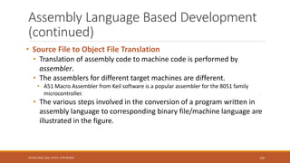
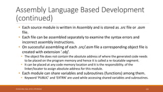
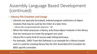
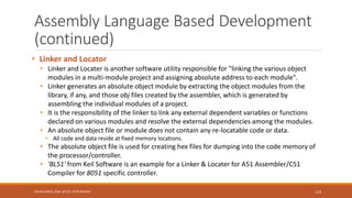
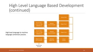

Embedded System
Design Concepts
EMBEDDED SYSTEMS (18EC62)
MODULE – 4
1
Shrishail Bhat, Dept. of ECE, AITM Bhatkal
Characteristics and
Quality Attributes of
Embedded Systems
2
Shrishail Bhat, Dept. of ECE, AITM Bhatkal
Characteristics of Embedded Systems
• Embedded systems possess certain specific characteristics.
• These characteristics are unique to each embedded system.
• Some of the important characteristics of an embedded system
are:
1. Application and domain specific
2. Reactive and Real Time
3. Operates in harsh environments
4. Distributed
5. Small size and weight
6. Power concerns
3
Shrishail Bhat, Dept. of ECE, AITM Bhatkal
Characteristics of Embedded Systems
(continued)
1. Application and Domain Specific
• Each embedded system has certain functions to perform and they
are developed in such a manner to do the intended functions
only.
• They cannot be used for any other purpose.
• For example, the embedded control unit of a microwave oven cannot be
replaced with an air conditioner's embedded control unit, because the
embedded control units of microwave oven and air conditioner are
specifically designed to perform certain specific tasks.
• Also an embedded control unit developed for a particular domain, say
telecom, cannot be replaced with another control unit designed to serve
another domain like consumer electronics.
4
Shrishail Bhat, Dept. of ECE, AITM Bhatkal
Characteristics of Embedded Systems
(continued)
2. Reactive and Real Time
• Embedded systems are in constant interaction with the real world
through sensors and user-defined input devices which are
connected to the input port of the system.
• Any changes happening in the real world (which is called an
Event) are captured by the sensors or input devices in Real Time
and the control algorithm running inside the unit reacts in a
designed manner to bring the controlled output variables to the
desired level.
• Embedded systems produce changes in output in response to the
changes in the input.
• So they are generally referred as Reactive Systems.
5
Shrishail Bhat, Dept. of ECE, AITM Bhatkal
Characteristics of Embedded Systems
(continued)
• Real Time System operation means the timing behaviour of
the system should be deterministic.
• The system should respond to requests or tasks in a known amount
of time.
• A Real Time system should not miss any deadlines for tasks
or operations.
• It is not necessary that all embedded systems should be Real
Time in operations.
• Embedded applications or systems which are mission critical,
like flight control systems, Antilock Brake Systems (ABS), etc.
are examples of Real Time systems.
6
Shrishail Bhat, Dept. of ECE, AITM Bhatkal
Characteristics of Embedded Systems
(continued)
3. Operates in Harsh Environment
• The environment in which the embedded system deployed may be a
dusty one or a high temperature zone or an area subject to vibrations
and shock.
• Systems placed in such areas should be capable to withstand all these
adverse operating conditions.
• The design should take care of the operating conditions of the area
where the system is going to implement.
• For example, if the system needs to be deployed in a high temperature zone, then
all the components used in the system should be of high temperature grade.
• Also proper shock absorption techniques should be provided to systems which are
going to be commissioned in places subject to high shock.
• Power supply fluctuations, corrosion and component aging, etc. are
the other factors that need to be taken into consideration for
embedded systems to work in harsh environments.
7
Shrishail Bhat, Dept. of ECE, AITM Bhatkal
Characteristics of Embedded Systems
(continued)
4. Distributed
• The term distributed means that embedded systems may be a part of larger systems.
• Many numbers of such distributed embedded systems form a single large embedded
control unit.
• For example, an automatic vending machine.
• It contains a card reader (for pre-paid vending systems), a vending unit, etc.
• Each of them are independent embedded units but they work together to perform the overall vending
function.
• Another example is the Automated Teller Machine (ATM).
• It contains a card reader embedded unit, responsible for reading and validating the user's ATM card,
transaction unit for performing transactions, a currency counter for dispatching/vending currency to the
authorised person and a printer unit for printing the transaction details.
• We can visualise these as independent embedded systems, but they work together to achieve a
common goal.
• Another typical example of a distributed embedded system is the Supervisory Control And Data
Acquisition (SCADA) system used in Control & Instrumentation applications, which contains physically
distributed individual embedded control units connected to a supervisory module.
8
Shrishail Bhat, Dept. of ECE, AITM Bhatkal
Characteristics of Embedded Systems
(continued)
5. Small Weight and Size
• Product aesthetics is an important factor in choosing a product.
• For example, when you plan to buy a new mobile phone, you may make a
comparative study on the pros and cons of the products available in the
market.
• Definitely the product aesthetics (size, weight, shape, style, etc.) will be one of the
deciding factors to choose a product.
• People believe in the phrase "Small is beautiful".
• Moreover it is convenient to handle a compact device than a bulky product.
• In embedded domain also compactness is a significant deciding factor.
• Most of the application demands small sized and low weight products.
9
Shrishail Bhat, Dept. of ECE, AITM Bhatkal
Characteristics of Embedded Systems
(continued)
6. Power Concerns
• Power management is another important factor that needs to be considered
in designing embedded systems.
• Embedded systems should be designed in such a way as to minimise the
heat dissipation by the system.
• The production of high amount of heat demands cooling requirements like
cooling fans which in turn occupies additional space and make the system
bulky.
• Select the design according to the low power components like low dropout
regulators, and controllers/processors with power saving modes.
• Also power management is a critical constraint in battery operated
application.
• The more the power consumption the less is the battery life.
10
Shrishail Bhat, Dept. of ECE, AITM Bhatkal
Quality Attributes of Embedded Systems
• Quality attributes are the non-functional requirements that
need to be documented properly in any system design.
• If the quality attributes are more concrete and measurable
it will give a positive impact on the system development
process and the end product.
• The quality attributes in any embedded system
development are broadly classified into two:
• Operational Quality Attributes
• Non-Operational Quality Attributes
11
Shrishail Bhat, Dept. of ECE, AITM Bhatkal
Operational Quality Attributes
• The operational quality attributes represent the relevant
quality attributes related to the embedded system when it is in
the operational mode or 'online' mode.
• The important operational quality attributes are:
1. Response
2. Throughput
3. Reliability
4. Maintainability
5. Security
6. Safety
12
Shrishail Bhat, Dept. of ECE, AITM Bhatkal
Operational Quality Attributes
(continued)
1. Response
• Response is a measure of quickness of the system.
• It gives you an idea about how fast the system is tracking the changes in
input variables.
• Most of the embedded systems demand fast response which should be
almost Real Time.
• For example, an embedded system deployed in flight control application should respond
in a Real Time manner.
• Any response delay in the system will create potential damages to the safety of the flight
as well as the passengers.
• It is not necessary that all embedded systems should be Real Time in
response.
• For example, the response time requirement for an electronic toy is not at all time-critical.
• There is no specific deadline that this system should respond within this particular
timeline.
13
Shrishail Bhat, Dept. of ECE, AITM Bhatkal
Operational Quality Attributes
(continued)
2. Throughput
• Throughput deals with the efficiency of a system.
• Throughput can be defined as the rate of production or operation of a
defined process over a stated period of time.
• The rates can be expressed in terms of units of products, batches
produced, or any other meaningful measurements.
• In the case of a Card Reader, throughput means how many transactions the
Reader can perform in a minute or in an hour or in a day.
• Throughput is generally measured in terms of 'Benchmark’.
• A 'Benchmark' is a reference point by which something can be measured.
• Benchmark can be a set of performance criteria that a product is expected to
meet or a standard product that can be used for comparing other products of the
same product line.
14
Shrishail Bhat, Dept. of ECE, AITM Bhatkal
Operational Quality Attributes
(continued)
3.Reliability
• Reliability is a measure of how much percentage you can rely
upon the proper functioning of the system or what is the
percentage susceptibility of the system to failures.
• System reliability is defined using two terms:
• Mean Time Between Failures (MTBF)
• Gives the frequency of failures in hours/weeks/months.
• Mean Time To Repair (MTTR)
• Specifies how long the system is allowed to be out of order following a
failure.
• For an embedded system with critical application need, it should be of
the order of minutes.
15
Shrishail Bhat, Dept. of ECE, AITM Bhatkal
Operational Quality Attributes
(continued)
4. Maintainability
• Maintainability deals with support and maintenance to the end user
or client in case of technical issues and product failures or on the basis
of a routine system check-up.
• Reliability and maintainability are considered as two complementary
disciplines.
• A more reliable system means a system with less corrective
maintainability requirements and vice versa.
• Maintainability can be broadly classified into two categories:
• Scheduled or Periodic Maintenance (preventive maintenance)
• For example, replacing the cartridge of a printer after each 'n' number of
printouts to get quality prints.
• Maintenance to unexpected failures (corrective maintenance)
• For example, repairing the printer if the paper feeding part fails.
16
Shrishail Bhat, Dept. of ECE, AITM Bhatkal
Operational Quality Attributes
(continued)
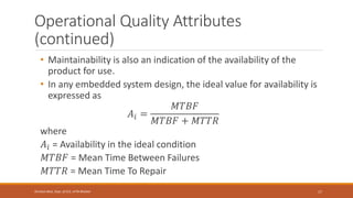
• Maintainability is also an indication of the availability of the
product for use.
• In any embedded system design, the ideal value for availability is
expressed as
𝐴𝑖 =
𝑀𝑇𝐵𝐹
𝑀𝑇𝐵𝐹 + 𝑀𝑇𝑇𝑅
where
𝐴𝑖 = Availability in the ideal condition
𝑀𝑇𝐵𝐹 = Mean Time Between Failures
𝑀𝑇𝑇𝑅 = Mean Time To Repair
17
Shrishail Bhat, Dept. of ECE, AITM Bhatkal
Operational Quality Attributes
(continued)
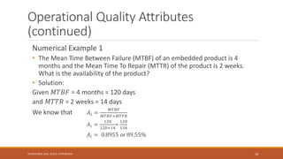
Numerical Example 1
• The Mean Time Between Failure (MTBF) of an embedded product is 4
months and the Mean Time To Repair (MTTR) of the product is 2 weeks.
What is the availability of the product?
• Solution:
Given 𝑀𝑇𝐵𝐹 = 4 months = 120 days
and 𝑀𝑇𝑇𝑅 = 2 weeks = 14 days
We know that 𝐴𝑖 =
𝑀𝑇𝐵𝐹
𝑀𝑇𝐵𝐹+𝑀𝑇𝑇𝑅
𝐴𝑖 =
120
120+14
=
120
134
𝐴𝑖 = 0.8955 or 89.55%
18
Shrishail Bhat, Dept. of ECE, AITM Bhatkal
Operational Quality Attributes
(continued)
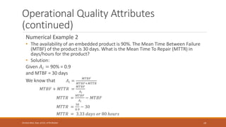
Numerical Example 2
• The availability of an embedded product is 90%. The Mean Time Between Failure
(MTBF) of the product is 30 days. What is the Mean Time To Repair (MTTR) in
days/hours for the product?
• Solution:
Given 𝐴𝑖 = 90% = 0.9
and MTBF = 30 days
We know that 𝐴𝑖 =
𝑀𝑇𝐵𝐹
𝑀𝑇𝐵𝐹+𝑀𝑇𝑇𝑅
𝑀𝑇𝐵𝐹 + 𝑀𝑇𝑇𝑅 =
𝑀𝑇𝐵𝐹
𝐴𝑖
𝑀𝑇𝑇𝑅 =
𝑀𝑇𝐵𝐹
𝐴𝑖
− 𝑀𝑇𝐵𝐹
𝑀𝑇𝑇𝑅 =
30
0.9
− 30
𝑀𝑇𝑇𝑅 = 3.33 𝑑𝑎𝑦𝑠 𝑜𝑟 80 ℎ𝑜𝑢𝑟𝑠
19
Shrishail Bhat, Dept. of ECE, AITM Bhatkal
Operational Quality Attributes
(continued)
5. Security
• Confidentiality, Integrity, and Availability are the three major measures of information security.
• Confidentiality deals with the protection of data and application from unauthorised disclosure.
• Integrity deals with the protection of data and application from unauthorised modification.
• Availability deals with protection of data and application from unauthorized users.
• A very good example of the 'Security' aspect in an embedded product is a Personal Digital
Assistant (PDA).
• The PDA can be either a shared resource (e.g. PDAs used in LAB setups) or an individual one.
• If it is a shared one there should be some mechanism in the form of a user name and password
to access into a particular person's profile—This is an example of 'Availability’.
• Also all data and applications present in the PDA need not be accessible to all users.
• Some of them are specifically accessible to administrators only.
• For achieving this, Administrator and user levels of security should be implemented —An
example of Confidentiality.
• Some data present in the PDA may be visible to all users but there may not be necessary
permissions to alter the data by the users.
• That is Read Only access is allocated to all users—An example of Integrity.
20
Shrishail Bhat, Dept. of ECE, AITM Bhatkal
Operational Quality Attributes
(continued)
6. Safety
• Safety deals with the possible damages that can happen to the
operators, public and the environment due to the breakdown of an
embedded system or due to the emission of radioactive or hazardous
materials from the embedded products.
• The breakdown of an embedded system may occur due to a hardware
failure or a firmware failure.
• Safety analysis is a must in product engineering to evaluate the
anticipated damages and determine the best course of action to bring
down the consequences of the damages to an acceptable level.
• Some of the safety threats are sudden (like product breakdown) and
some of them are gradual (like hazardous emissions from the product).
21
Shrishail Bhat, Dept. of ECE, AITM Bhatkal
Non-Operational Quality Attributes
• The quality attributes that needs to be addressed for the
product 'not’ on the basis of operational aspects are
grouped under this category.
• The important non-operational quality attributes are:
1. Testability & Debug-ability
2. Evolvability
3. Portability
4. Time-to-prototype and market
5. Per unit and total cost
22
Shrishail Bhat, Dept. of ECE, AITM Bhatkal
Non-Operational Quality Attributes
(continued)
1. Testability & Debug-ability
• Testability deals with how easily one can test his/her design, application and
by which means he/she can test it.
• For an embedded product, testability is applicable to both the embedded
hardware and firmware.
• Embedded hardware testing ensures that the peripherals and the total hardware
functions in the desired manner, whereas firmware testing ensures that the
firmware is functioning in the expected way.
• Debug-ability is a means of debugging the product as such for figuring out
the probable sources that create unexpected behaviour in the total system.
• Debug-ability has two aspects in the embedded system development context,
namely, hardware level debugging and firmware level debugging.
• Hardware debugging is used for figuring out the issues created by hardware
problems whereas firmware debugging is employed to figure out the probable
errors that appear as a result of flaws in the firmware.
23
Shrishail Bhat, Dept. of ECE, AITM Bhatkal
Non-Operational Quality Attributes
(continued)
2.Evolvability
• Evolvability is referred as the non-heritable variation (in
Biology)
• For an embedded system, the quality attribute 'Evolvability’
refers to the ease with which the embedded product
(including firmware and hardware) can be modified to take
advantage of new firmware or hardware technologies.
24
Shrishail Bhat, Dept. of ECE, AITM Bhatkal
Non-Operational Quality Attributes
(continued)
3. Portability
• Portability is a measure of 'system independence’.
• An embedded product is said to be portable if the product is
capable of functioning 'as such' in various environments, target
processors/controllers and embedded operating systems.
• A standard embedded product should always be flexible and
portable.
• In embedded products, the term 'porting' represents the
migration of the embedded firmware written for one target
processor (e.g. Intel x86) to a different target processor (say
Hitachi SH3 processor).
25
Shrishail Bhat, Dept. of ECE, AITM Bhatkal
Non-Operational Quality Attributes
(continued)
• If the firmware is written in a high level language like ‘C’, it is very
easy to port the firmware
• It has only few target processor-specific functions which can be replaced
with the ones for the new target processor and re-compiling the program
for the new target processor-specific settings.
• The program then needs to be re-compiled to generate the new target
processor-specific machine codes.
• If the firmware is written in Assembly Language for a particular
family of processor (say x86 family), the portability is poor.
• It is very difficult to translate the assembly language instructions to the
new target processor specific language.
26
Shrishail Bhat, Dept. of ECE, AITM Bhatkal
Non-Operational Quality Attributes
(continued)
4.Time-to-Prototype and Market
• Time-to-market is the time elapsed between the
conceptualisation of a product and the time at which the
product is ready for selling (for commercial product) or use
(for non-commercial products).
• The commercial embedded product market is highly
competitive and time-to-market the product is a critical
factor in the success of a commercial embedded product.
• Competitor might release their product before you do.
• The technology used might have superseded with a new technology.
27
Shrishail Bhat, Dept. of ECE, AITM Bhatkal
Non-Operational Quality Attributes
(continued)
• Product prototyping helps a lot in reducing time-to-market.
• Prototyping is an informal kind of rapid product development
in which the important features of the product under
consideration are developed.
• The time-to-prototype is also another critical factor.
• If the prototype is developed faster, the actual estimated
development time can be brought down significantly.
• In order to shorten the time to prototype, make use of all possible
options like the use of off-the-shelf components, re-usable assets,
etc.
28
Shrishail Bhat, Dept. of ECE, AITM Bhatkal
Non-Operational Quality Attributes
(continued)
5. Per Unit Cost and Revenue
• Cost is a factor which is closely monitored by both end user and
product manufacturer.
• Cost is a highly sensitive factor for commercial products.
• Any failure to position the cost of a commercial product at a
nominal rate, may lead to the failure of the product in the
market.
• Proper market study and cost benefit analysis should be carried
out before taking a decision on the per-unit cost of the
embedded product.
• The budget and total system cost should be properly balanced to
provide a marginal profit.
29
Shrishail Bhat, Dept. of ECE, AITM Bhatkal
Non-Operational Quality Attributes
(continued)
• The product life cycle of every embedded product has different phases:
1. Design and Development Phase:
• The product idea generation, prototyping, Roadmap definition, actual product design and development are the
activities carried out during this phase.
• There is only investment and no returns.
2. Product Introduction Phase:
• Once the product is ready to sell, it is introduced to the market.
• During the initial period the sales and revenue will be low.
• There won't be much competition and the product sales and revenue increases with time.
3. Growth Phase
• The product grabs high market share.
4. Maturity Phase:
• The growth and sales will be steady and the revenue reaches at its peak.
5. Product Retirement/Decline Phase:
• Drop in sales volume, market share and revenue.
• The decline happens due to various reasons like competition from similar product with enhanced features or
technology changes, etc.
• At some point of the decline stage, the manufacturer announces discontinuing of the product.
30
Shrishail Bhat, Dept. of ECE, AITM Bhatkal
Non-Operational Quality Attributes
(continued)
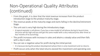
• The different stages of the embedded products life cycle—revenue, unit cost
and profit in each stage are represented in the following Product Life-cycle
graph.
31
Shrishail Bhat, Dept. of ECE, AITM Bhatkal
Product Life Cycle (PLC) curve
Non-Operational Quality Attributes
(continued)
• From the graph, it is clear that the total revenue increases from the product
introduction stage to the product maturity stage.
• The revenue peaks at the maturity stage and starts falling in the decline/retirement
Stage.
• The unit cost is very high during the introductory stage.
• A typical example is cell phone; if you buy a new model of cell phone during its launch time,
the price will be high and you will get the same model with a very reduced price after three or
four months of its launching).
• The profit increases with increase in sales and attains a steady value and then falls
with a dip in sales.
• You can see a negative value for profit during the initial period.
• It is because during the product development phase there is only investment and no returns.
• Profit occurs only when the total returns exceed the investment and operating cost.
32
Shrishail Bhat, Dept. of ECE, AITM Bhatkal
Embedded Systems –
Application and Domain
Specific
33
Shrishail Bhat, Dept. of ECE, AITM Bhatkal
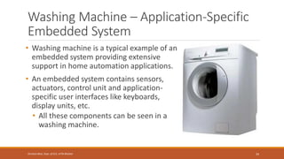
Washing Machine – Application-Specific
Embedded System
• Washing machine is a typical example of an
embedded system providing extensive
support in home automation applications.
• An embedded system contains sensors,
actuators, control unit and application-
specific user interfaces like keyboards,
display units, etc.
• All these components can be seen in a
washing machine.
34
Shrishail Bhat, Dept. of ECE, AITM Bhatkal
Washing Machine – Application-Specific
Embedded System (continued)
35
Shrishail Bhat, Dept. of ECE, AITM Bhatkal
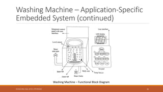
Washing Machine – Functional Block Diagram
Washing Machine – Application-Specific
Embedded System (continued)
• The actuator part of the washing machine consists of a motorised agitator,
tumble tub, water drawing pump and inlet valve to control the flow of water
into the unit.
• The sensor part consists of the water temperature sensor, level sensor, etc.
• The control part contains a microprocessor/controller based board with
interfaces to the sensors and actuators.
• The sensor data is fed back to the control unit and the control unit generates
the necessary actuator outputs.
• The control unit also provides connectivity to user interfaces like keypad for
setting the washing time, selecting the type of material to be washed like light,
medium, heavy duty, etc.
• User feedback is reflected through the display unit and LEDs connected to the
control board.
36
Shrishail Bhat, Dept. of ECE, AITM Bhatkal
Washing Machine – Application-Specific
Embedded System (continued)
37
Shrishail Bhat, Dept. of ECE, AITM Bhatkal
Top Loading
Washing Machine
Front Loading
Washing Machine
Washing Machine – Application-Specific
Embedded System (continued)
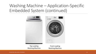
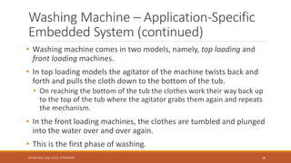
• Washing machine comes in two models, namely, top loading and
front loading machines.
• In top loading models the agitator of the machine twists back and
forth and pulls the cloth down to the bottom of the tub.
• On reaching the bottom of the tub the clothes work their way back up
to the top of the tub where the agitator grabs them again and repeats
the mechanism.
• In the front loading machines, the clothes are tumbled and plunged
into the water over and over again.
• This is the first phase of washing.
38
Shrishail Bhat, Dept. of ECE, AITM Bhatkal
Washing Machine – Application-Specific
Embedded System (continued)
• In the second phase of washing, water is pumped out from the tub
and the inner tub uses centrifugal force to wring out more water
from the clothes by spinning at several hundred Rotations Per
Minute (RPM).
• This is called a 'Spin Phase’.
• The inner tub of the machine contains a number of holes and
during the spin cycle the inner tub spins, and forces the water out
through these holes to the stationary outer tub from which it is
drained off through the outlet pipe.
39
Shrishail Bhat, Dept. of ECE, AITM Bhatkal
Washing Machine – Application-Specific
Embedded System (continued)
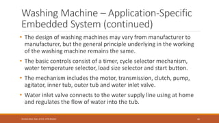
• The design of washing machines may vary from manufacturer to
manufacturer, but the general principle underlying in the working
of the washing machine remains the same.
• The basic controls consist of a timer, cycle selector mechanism,
water temperature selector, load size selector and start button.
• The mechanism includes the motor, transmission, clutch, pump,
agitator, inner tub, outer tub and water inlet valve.
• Water inlet valve connects to the water supply line using at home
and regulates the flow of water into the tub.
40
Shrishail Bhat, Dept. of ECE, AITM Bhatkal
Washing Machine – Application-Specific
Embedded System (continued)
41
Shrishail Bhat, Dept. of ECE, AITM Bhatkal
Integrated Control Panel of a Washing Machine
Washing Machine – Application-Specific
Embedded System (continued)
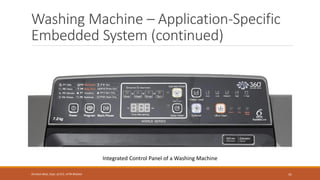
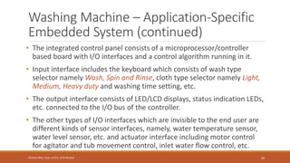
• The integrated control panel consists of a microprocessor/controller
based board with I/O interfaces and a control algorithm running in it.
• Input interface includes the keyboard which consists of wash type
selector namely Wash, Spin and Rinse, cloth type selector namely Light,
Medium, Heavy duty and washing time setting, etc.
• The output interface consists of LED/LCD displays, status indication LEDs,
etc. connected to the I/O bus of the controller.
• The other types of I/O interfaces which are invisible to the end user are
different kinds of sensor interfaces, namely, water temperature sensor,
water level sensor, etc. and actuator interface including motor control
for agitator and tub movement control, inlet water flow control, etc.
42
Shrishail Bhat, Dept. of ECE, AITM Bhatkal
Automotive – Domain-Specific
Embedded System
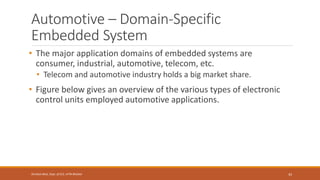
• The major application domains of embedded systems are
consumer, industrial, automotive, telecom, etc.
• Telecom and automotive industry holds a big market share.
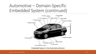
• Figure below gives an overview of the various types of electronic
control units employed automotive applications.
43
Shrishail Bhat, Dept. of ECE, AITM Bhatkal
Automotive – Domain-Specific
Embedded System (continued)
44
Shrishail Bhat, Dept. of ECE, AITM Bhatkal
Embedded System in the Automotive Domain
Inner Workings of Automotive
Embedded Systems
• Automotive embedded systems are the one where electronics take
control over the mechanical systems.
• The presence of automotive embedded system in a vehicle varies
from simple mirror and wiper controls to complex air bag controller
and antilock brake systems (ABS).
• Automotive embedded systems are normally built around
microcontrollers or DSPs or a hybrid of the two and are generally
known as Electronic Control Units (ECUs).
• The number of embedded controllers in an ordinary vehicle varies
from 20 to 40 whereas a luxury vehicle like Mercedes S and BMW 7
may contain 75 to 100 numbers of embedded controllers.
45
Shrishail Bhat, Dept. of ECE, AITM Bhatkal
Inner Workings of Automotive
Embedded Systems (continued)
• Government regulations on fuel economy, environmental factors
and emission standards and increasing customer demands on
safety, comfort and infotainment forces the automotive
manufactures to opt for sophisticated embedded control units
within the vehicle.
• The first embedded system used in automotive application was the
microprocessor based fuel injection system introduced by
Volkswagen 1600 in 1968.
46
Shrishail Bhat, Dept. of ECE, AITM Bhatkal
Inner Workings of Automotive
Embedded Systems (continued)
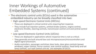
• The electronic control units (ECUs) used in the automotive
embedded industry can be broadly classified into two:
• High-speed Electronic Control Units (HECUs):
• These are deployed in critical control units requiring fast response.
• They include fuel injection systems, antilock brake systems, engine control,
electronic throttle, steering controls, transmission control unit and central control
unit.
• Low-speed Electronic Control Units (LECUs):
• These are deployed in applications where response time is not so critical.
• They generally are built around low cost microprocessors/microcontrollers and
digital signal processors.
• Audio controllers, passenger and driver door locks, door glass controls (power
windows), wiper control, mirror control, seat control systems, head lamp and tail
lamp controls, sun roof control unit etc. are examples of LECUs.
47
Shrishail Bhat, Dept. of ECE, AITM Bhatkal
Automotive Communication Buses
• Automotive applications make use of serial buses for
communication, which greatly reduces the amount of wiring
required inside a vehicle.
• Different types of serial interface buses are:
• Controller Area Network (CAN) Bus
• Local Interconnect Network (LIN) Bus
• Media-Oriented System Transport (MOST) Bus
48
Shrishail Bhat, Dept. of ECE, AITM Bhatkal
Automotive Communication Buses
(continued)
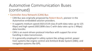
• Controller Area Network (CAN) Bus
• CAN Bus was originally proposed by Robert Bosch, pioneer in the
Automotive embedded solution providers.
• It supports medium speed (ISO11519-class B with data rates up to 125
Kbps) and high speed (IS011898 class C with data rates up to 1 Mbps)
data transfer.
• CAN is an event-driven protocol interface with support for error
handling in data transmission.
• It is generally employed in safety system like airbag control; power
train systems like engine control and Antilock Brake System (ABS); and
navigation systems like GPS.
49
Shrishail Bhat, Dept. of ECE, AITM Bhatkal
Automotive Communication Buses
(continued)
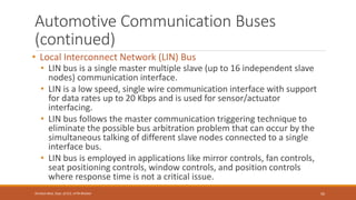
• Local Interconnect Network (LIN) Bus
• LIN bus is a single master multiple slave (up to 16 independent slave
nodes) communication interface.
• LIN is a low speed, single wire communication interface with support
for data rates up to 20 Kbps and is used for sensor/actuator
interfacing.
• LIN bus follows the master communication triggering technique to
eliminate the possible bus arbitration problem that can occur by the
simultaneous talking of different slave nodes connected to a single
interface bus.
• LIN bus is employed in applications like mirror controls, fan controls,
seat positioning controls, window controls, and position controls
where response time is not a critical issue.
50
Shrishail Bhat, Dept. of ECE, AITM Bhatkal
Automotive Communication Buses
(continued)
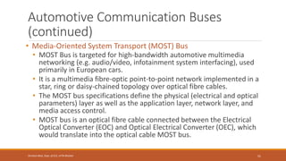
• Media-Oriented System Transport (MOST) Bus
• MOST Bus is targeted for high-bandwidth automotive multimedia
networking (e.g. audio/video, infotainment system interfacing), used
primarily in European cars.
• It is a multimedia fibre-optic point-to-point network implemented in a
star, ring or daisy-chained topology over optical fibre cables.
• The MOST bus specifications define the physical (electrical and optical
parameters) layer as well as the application layer, network layer, and
media access control.
• MOST bus is an optical fibre cable connected between the Electrical
Optical Converter (EOC) and Optical Electrical Converter (OEC), which
would translate into the optical cable MOST bus.
51
Shrishail Bhat, Dept. of ECE, AITM Bhatkal
Hardware Software Co-
Design and Program
Modelling
52
Shrishail Bhat, Dept. of ECE, AITM Bhatkal
Hardware Software Co-Design
• In the traditional embedded system development approach, the hardware
software partitioning is done at an early stage.
• Engineers from the software group take care of the software architecture
development and implementation, whereas engineers from the hardware group are
responsible for building the hardware required for the product.
• There is less interaction between the two teams and the development happens
either serially or in parallel.
• Once the hardware and software are ready, the integration is performed.
• The increasing competition in the commercial market and need for reduced
'time-to-market' the product calls for a novel approach for embedded system
design in which the hardware and software are co-developed instead of
independently developing both.
53
Shrishail Bhat, Dept. of ECE, AITM Bhatkal
Hardware Software Co-Design
(continued)
• During the co-design process, the product requirements captured from the
customer are converted into system level needs or processing requirements.
• At this point of time it is not segregated as either hardware requirement or
software requirement, instead it is specified as functional requirement.
• The system level processing requirements are then transferred into functions
which can be simulated and verified against performance and functionality.
• The Architecture design follows the system design.
• The partition of system level processing requirements into hardware and software
takes place during the architecture design phase.
• Each system level processing requirement is mapped as either hardware and/or
software requirement.
• The partitioning is performed based on the hardware-software trade-offs.
54
Shrishail Bhat, Dept. of ECE, AITM Bhatkal
Hardware Software Co-Design
(continued)
• The architectural design results in the detailed behavioural
description of the hardware requirement and the definition of the
software required for the hardware.
• The processing requirement behaviour is usually captured using
computational models.
• The models representing the software processing requirements are
translated into firmware implementation using programming
languages.
55
Shrishail Bhat, Dept. of ECE, AITM Bhatkal
Fundamental Issues in Hardware
Software Co-Design
• The fundamental issues in hardware software co-design are:
• Selecting the Model
• Selecting the Architecture
• Selecting the Language
• Partitioning System Requirements into Hardware and Software
56
Shrishail Bhat, Dept. of ECE, AITM Bhatkal
Fundamental Issues in Hardware
Software Co-Design (continued)
• Selecting the Model
• In hardware software co-design, models are used for capturing and describing the
system characteristics.
• A model is a formal system consisting of objects and composition rules.
• It is hard to make a decision on which model should be followed in a particular
system design.
• Most often designers switch between a variety of models from the requirements
specification to the implementation aspect of the system design.
• The reason being, the objective varies with each phase.
• For example, at the specification stage, only the functionality of the system is in focus and not the
implementation information.
• When the design moves to the implementation aspect, the information about the system components
is revealed and the designer has to switch to a model capable of capturing the system's structure.
57
Shrishail Bhat, Dept. of ECE, AITM Bhatkal
Fundamental Issues in Hardware
Software Co-Design (continued)
• Selecting the Architecture
• A model only captures the system characteristics and does not provide information
on 'how the system can be manufactured?’.
• The architecture specifies how a system is going to implement in terms of the
number and types of different components and the interconnection among them.
• The commonly used architectures in system design are Controller Architecture,
Datapath Architecture, Complex Instruction Set Computing (CISC), Reduced
Instruction Set Computing (RISC), Very Long Instruction Word Computing (VLIW),
Single Instruction Multiple Data (SIMD), Multiple Instruction Multiple Data (MIMD),
etc.
• Some of them fall into Application Specific Architecture Class (like controller architecture),
while others fall into either general purpose architecture class (CISC, RISC, etc.) or Parallel
processing class (like VLIW, SIMD, MIMD, etc.).
58
Shrishail Bhat, Dept. of ECE, AITM Bhatkal
Fundamental Issues in Hardware
Software Co-Design (continued)
• The controller architecture implements the finite state machine model using a state
register and two combinational circuits.
• The state register holds the present state and the combinational circuits implement the logic
for next state and output.
• The datapath architecture is best suited for implementing the data flow graph
model where the output is generated as a result of a set of predefined
computations on the input data.
• A datapath represents a channel between the input and output
• The datapath may contain registers, counters, register files, memories and ports along with
high speed arithmetic units.
• Ports connect the datapath to multiple buses.
• Most of the time the arithmetic units are connected in parallel with pipelining support for
bringing high performance.
59
Shrishail Bhat, Dept. of ECE, AITM Bhatkal
Fundamental Issues in Hardware
Software Co-Design (continued)
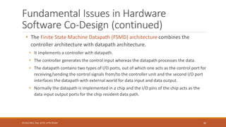
• The Finite State Machine Datapath (FSMD) architecture combines the
controller architecture with datapath architecture.
• It implements a controller with datapath.
• The controller generates the control input whereas the datapath processes the data.
• The datapath contains two types of I/O ports, out of which one acts as the control port for
receiving/sending the control signals from/to the controller unit and the second I/O port
interfaces the datapath with external world for data input and data output.
• Normally the datapath is implemented in a chip and the I/O pins of the chip acts as the
data input output ports for the chip resident data path.
60
Shrishail Bhat, Dept. of ECE, AITM Bhatkal
Fundamental Issues in Hardware
Software Co-Design (continued)
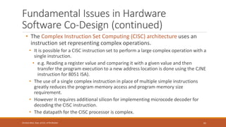
• The Complex Instruction Set Computing (CISC) architecture uses an
instruction set representing complex operations.
• It is possible for a CISC instruction set to perform a large complex operation with a
single instruction.
• e.g. Reading a register value and comparing it with a given value and then
transfer the program execution to a new address location is done using the CJNE
instruction for 8051 ISA).
• The use of a single complex instruction in place of multiple simple instructions
greatly reduces the program memory access and program memory size
requirement.
• However it requires additional silicon for implementing microcode decoder for
decoding the CISC instruction.
• The datapath for the CISC processor is complex.
61
Shrishail Bhat, Dept. of ECE, AITM Bhatkal
Fundamental Issues in Hardware
Software Co-Design (continued)
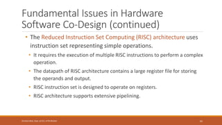
• The Reduced Instruction Set Computing (RISC) architecture uses
instruction set representing simple operations.
• It requires the execution of multiple RISC instructions to perform a complex
operation.
• The datapath of RISC architecture contains a large register file for storing
the operands and output.
• RISC instruction set is designed to operate on registers.
• RISC architecture supports extensive pipelining.
62
Shrishail Bhat, Dept. of ECE, AITM Bhatkal
Fundamental Issues in Hardware
Software Co-Design (continued)
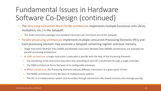
• The Very Long Instruction Word (VLIW) architecture implements multiple functional units (ALUs,
multipliers, etc.) in the datapath.
• The VLIW instruction packages one standard instruction per functional unit of the datapath.
• Parallel processing architecture implements multiple concurrent Processing Elements (PEs) and
each processing element may associate a datapath containing register and local memory.
• Single Instruction Multiple Data (SIMD) and Multiple Instruction Multiple Data (MIMD) architectures are examples for
parallel processing architecture.
• In SIMD architecture, a single instruction is executed in parallel with the help of the Processing Elements.
• The scheduling of the instruction execution and controlling of each PE is performed through a single controller.
• The SIMD architecture forms the basis of re-configurable processor.
• In MIMD architecture, the Processing Elements execute different instructions at a given point of time.
• The MIMD architecture forms the basis of multiprocessor systems.
• The PEs in a multiprocessor system communicates through mechanisms like shared memory and message passing.
63
Shrishail Bhat, Dept. of ECE, AITM Bhatkal
Fundamental Issues in Hardware
Software Co-Design (continued)
• Selecting the Language
• A programming language captures a 'Computational Model' and maps it into
architecture.
• There is no hard and fast rule to specify this language should be used for capturing
this model.
• A model can be captured using multiple programming languages like C, C++, C#,
Java, etc. for software implementations and languages like VHDL, System C, Verilog,
etc. for hardware implementations.
• On the other hand, a single language can be used for capturing a variety of models.
• Certain languages are good in capturing certain computational model.
• For example, C++ is a good candidate for capturing an object oriented model.
• The only pre-requisite in selecting a programming language for capturing a model is
that the language should capture the model easily.
64
Shrishail Bhat, Dept. of ECE, AITM Bhatkal
Fundamental Issues in Hardware
Software Co-Design (continued)
• Partitioning System Requirements into Hardware and Software
• From an implementation perspective, it may be possible to
implement the system requirements in either hardware or
software (firmware).
• It is a tough decision making task to figure out which one to opt.
• Various hardware software trade-offs are used for making a
decision on the hardware-software partitioning.
65
Shrishail Bhat, Dept. of ECE, AITM Bhatkal
Computational Models in Embedded
Design
• The commonly used computational models in embedded system
design are:
• Data Flow Graph Model
• Control Data Flow Graph Model
• State Machine Model
• Sequential Program Model
• Concurrent/Communicating Process Model
• Object-Oriented Model
66
Shrishail Bhat, Dept. of ECE, AITM Bhatkal
Data Flow Graph/Diagram (DFG) Model
• The Data Flow Graph (DFG) model translates the data processing
requirements into a data flow graph.
• It is a data driven model in which the program execution is
determined by data.
• This model emphasises on the data and operations on the data
which transforms the input data to output data.
• Embedded applications which are computational intensive and data
driven are modelled using the DFG model.
• DSP applications are typical examples for it.
67
Shrishail Bhat, Dept. of ECE, AITM Bhatkal
Data Flow Graph/Diagram (DFG) Model
(continued)
• Data Flow Graph (DFG) is a visual model in which the operation on the
data (process) is represented using a block (circle) and data flow is
represented using arrows.
• An inward arrow to the process (circle) represents input data and an
outward arrow from the process (circle) represents output data in DFG
notation.
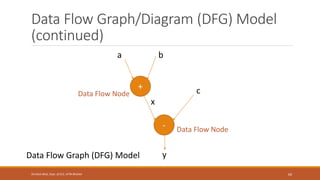
• Suppose one of the functions in our application contains the
computational requirement 𝑥 = 𝑎 + 𝑏 and 𝑦 = 𝑥 − 𝑐.
• Figure illustrates the implementation of a DFG model for implementing
these requirements.
68
Shrishail Bhat, Dept. of ECE, AITM Bhatkal
Data Flow Graph/Diagram (DFG) Model
(continued)
69
Shrishail Bhat, Dept. of ECE, AITM Bhatkal
+
-
b
a
c
x
y
Data Flow Graph (DFG) Model
Data Flow Node
Data Flow Node
Data Flow Graph/Diagram (DFG) Model
(continued)
• In a DFG model, a data path is the data flow path from input to
output.
• A DFG model is said to be acyclic DFG (ADFG) if it doesn't contain
multiple values for the input variable and multiple output values for
a given set of input(s).
• Feedback inputs (Output is fed back to Input), events, etc. are
examples for non-acyclic inputs.
• A DFG model translates the program as a single sequential process
execution.
70
Shrishail Bhat, Dept. of ECE, AITM Bhatkal
Control Data Flow Graph/Diagram
(CDFG) Model
• The DFG model is a data driven model in which the execution is
controlled by data and it doesn't involve any control operations
(conditionals).
• The Control DFG (CDFG) model is used for modelling applications
involving conditional program execution.
• CDFG models contains both data operations and control operations.
• The CDFG uses Data Flow Graph (DFG) as element and conditional
(constructs) as decision makers.
• CDFG contains both data flow nodes and decision nodes, whereas DFG
contains only data flow nodes.
71
Shrishail Bhat, Dept. of ECE, AITM Bhatkal
Control Data Flow Graph/Diagram
(CDFG) Model (continued)
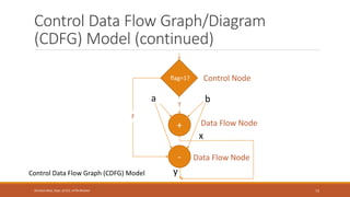
• Consider the implementation of the CDFG for the following requirement.
• 𝐼𝑓 𝑓𝑙𝑎𝑔 = 1, 𝑥 = 𝑎 + 𝑏; 𝑒𝑙𝑠𝑒 𝑦 = 𝑎 − 𝑏;
• This requirement contains a decision making process.
• The CDFG model for the same is given in the figure.
• The control node is represented by a 'Diamond' block which is the decision
making element in a normal flow chart based design.
• CDFG translates the requirement, which is modelled to a concurrent process
model.
• The decision on which process is to be executed is determined by the control
node.
72
Shrishail Bhat, Dept. of ECE, AITM Bhatkal
Control Data Flow Graph/Diagram
(CDFG) Model (continued)
73
Shrishail Bhat, Dept. of ECE, AITM Bhatkal
+
-
b
a
x
Control Data Flow Graph (CDFG) Model
Data Flow Node
Data Flow Node
flag=1? Control Node
y
T
F
Control Data Flow Graph/Diagram
(CDFG) Model (continued)
• A real world example for modelling the embedded application using
CDFG is capturing and saving of the image to a format set by the user in
a digital still camera.
• Here everything is data driven.
• Analog Front End converts the CCD sensor generated analog signal to Digital Signal
• The data from ADC is stored to a frame buffer for the use of a media processor
which performs various operations like, auto correction, white balance adjusting,
etc.
• The decision on, in which format the image is stored (formats like JPEG,
TIFF, BMP, etc.) is controlled by the camera settings, configured by the
user.
74
Shrishail Bhat, Dept. of ECE, AITM Bhatkal
State Machine Model
• The State Machine Model is used for modelling reactive or event-driven
embedded systems whose processing behaviour are dependent on state
transitions.
• Embedded systems used in the control and industrial applications are typical
examples for event driven systems.
• The State Machine model describes the system behaviour with 'States',
'Events', 'Actions' and 'Transitions’.
• State is a representation of a current situation.
• An event is an input to the state.
• The event acts as stimuli for state transition.
• Transition is the movement from one state to another.
• Action is an activity to be performed by the state machine.
75
Shrishail Bhat, Dept. of ECE, AITM Bhatkal
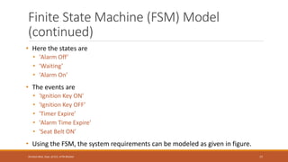
Finite State Machine (FSM) Model
• A Finite State Machine (FSM) model is one in which the number of states are
finite.
• The system is described using a finite number of possible states.
• As an example, let us consider the design of an embedded system for
driver/passenger 'Seat Belt Warning' in an automotive using the FSM model.
• The system requirements are captured as.
1. When the vehicle ignition is turned on and the seat belt is not fastened within 10
seconds of ignition ON, the system generates an alarm signal for 5 seconds.
2. The Alarm is turned off when the alarm time (5 seconds) expires or if the
driver/passenger fastens the belt or if the ignition switch is turned off, whichever
happens first.
76
Shrishail Bhat, Dept. of ECE, AITM Bhatkal
Finite State Machine (FSM) Model
(continued)
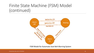
• Here the states are
• 'Alarm Off’
• 'Waiting’
• 'Alarm On’
• The events are
• 'Ignition Key ON’
• 'Ignition Key OFF’
• 'Timer Expire’
• 'Alarm Time Expire’
• 'Seat Belt ON’
• Using the FSM, the system requirements can be modeled as given in figure.
77
Shrishail Bhat, Dept. of ECE, AITM Bhatkal
Finite State Machine (FSM) Model
(continued)
78
Shrishail Bhat, Dept. of ECE, AITM Bhatkal
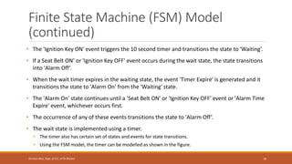
FSM Model for Automatic Seat Belt Warning System
Alarm
Off
Alarm
On
Waiting
Finite State Machine (FSM) Model
(continued)
• The 'Ignition Key ON' event triggers the 10 second timer and transitions the state to 'Waiting’.
• If a Seat Belt ON’ or 'Ignition Key OFF' event occurs during the wait state, the state transitions
into 'Alarm Off’.
• When the wait timer expires in the waiting state, the event 'Timer Expire' is generated and it
transitions the state to 'Alarm On' from the 'Waiting' state.
• The 'Alarm On' state continues until a 'Seat Belt ON' or 'Ignition Key OFF' event or 'Alarm Time
Expire' event, whichever occurs first.
• The occurrence of any of these events transitions the state to 'Alarm Off’.
• The wait state is implemented using a timer.
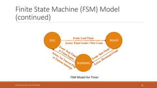
• The timer also has certain set of states and events for state transitions.
• Using the FSM model, the timer can be modelled as shown in the figure.
79
Shrishail Bhat, Dept. of ECE, AITM Bhatkal
Finite State Machine (FSM) Model
(continued)
80
Shrishail Bhat, Dept. of ECE, AITM Bhatkal
FSM Model for Timer
IDLE
RUNNING
READY
Finite State Machine (FSM) Model
(continued)
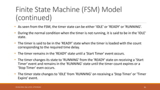
• As seen from the FSM, the timer state can be either 'IDLE' or 'READY' or 'RUNNING’.
• During the normal condition when the timer is not running, it is said to be in the 'IDLE'
state.
• The timer is said to be in the 'READY’ state when the timer is loaded with the count
corresponding to the required time delay.
• The timer remains in the 'READY' state until a 'Start Timer' event occurs.
• The timer changes its state to 'RUNNING' from the 'READY' state on receiving a 'Start
Timer' event and remains in the 'RUNNING' state until the timer count expires or a
'Stop Timer' even occurs.
• The timer state changes to 'IDLE' from 'RUNNING' on receiving a 'Stop Timer' or 'Timer
Expire' event.
81
Shrishail Bhat, Dept. of ECE, AITM Bhatkal
FSM Model - Example 1
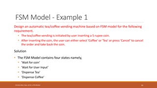
Design an automatic tea/coffee vending machine based on FSM model for the following
requirement.
• The tea/coffee vending is initiated by user inserting a 5 rupee coin.
• After inserting the coin, the user can either select 'Coffee' or 'Tea' or press 'Cancel' to cancel
the order and take back the coin.
Solution
• The FSM Model contains four states namely,
• 'Wait for coin’
• 'Wait for User Input’
• 'Dispense Tea'
• 'Dispense Coffee'
82
Shrishail Bhat, Dept. of ECE, AITM Bhatkal
FSM Model - Example 1 (continued)
83
Shrishail Bhat, Dept. of ECE, AITM Bhatkal
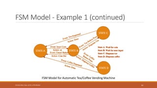
FSM Model for Automatic Tea/Coffee Vending Machine
STATE A
STATE D
STATE C
STATE B
FSM Model - Example 1 (continued)
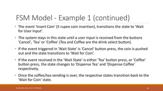
• The event 'Insert Coin' (5 rupee coin insertion), transitions the state to 'Wait
for User Input’.
• The system stays in this state until a user input is received from the buttons
'Cancel', 'Tea' or 'Coffee' (Tea and Coffee are the drink select button).
• If the event triggered in 'Wait State' is 'Cancel' button press, the coin is pushed
out and the state transitions to 'Wait for Coin’.
• If the event received in the 'Wait State' is either 'Tea' button press, or 'Coffee'
button press, the state changes to 'Dispense Tea' and 'Dispense Coffee'
respectively.
• Once the coffee/tea vending is over, the respective states transition back to the
'Wait for Coin' state.
84
Shrishail Bhat, Dept. of ECE, AITM Bhatkal
FSM Model - Example 2
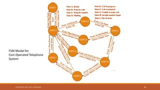
Design a coin operated public telephone unit based on FSM model for the following
requirements.
1. The calling process is initiated by lifting the receiver (off-hook) of the telephone unit.
2. After lifting the phone the user needs to insert a 1 rupee coin to make the call.
3. If the line is busy, the coin is returned on placing the receiver back on the hook (on-hook).
4. If the line is through, the user is allowed to talk till 60 seconds and at the end of 45th
second, prompt for inserting another 1 rupee coin for continuing the call is initiated.
5. If the user doesn't insert another 1 rupee coin, the call is terminated on completing the 60
seconds time slot.
6. The system is ready to accept new call request when the receiver is placed back on the
hook (on-hook).
7. The system goes to the 'Out of Order' state when there is a line fault.
85
Shrishail Bhat, Dept. of ECE, AITM Bhatkal
86
Shrishail Bhat, Dept. of ECE, AITM Bhatkal
FSM Model for
Coin Operated Telephone
System
STATE A
STATE F
STATE G
STATE H
STATE B
STATE I
STATE C
STATE D
STATE E
Sequential Program Model
• In the Sequential Program Model, the functions or processing
requirements are executed in sequence.
• It is same as the conventional procedural programming.
• Here the program instructions are iterated and executed
conditionally and the data gets transformed through a series of
operations.
• Finite State Machines (FSMs) and Flow Charts are used for
modelling sequential program.
• The FSM approach represents the states, events, transitions and actions,
whereas the Flow Chart models the execution flow.
87
Shrishail Bhat, Dept. of ECE, AITM Bhatkal
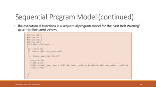
#define ON 1
#define OFF 0
#define YES 1
#define NO 0
void seat_belt_warn()
{
wait_10sec();
if (check_ignition_key()==ON)
{
if (check_seat_belt()==OFF)
{
set_timer(5);
start_alarm();
while ((check_seat_belt()==OFF)&&(check_ignition_key()==ON)&&(timer_expire()==NO));
stop_alarm();
}
}
}
}
Sequential Program Model (continued)
• The execution of functions in a sequential program model for the 'Seat Belt Warning'
system is illustrated below:
88
Shrishail Bhat, Dept. of ECE, AITM Bhatkal
89
Shrishail Bhat, Dept. of ECE, AITM Bhatkal
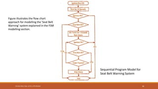
Sequential Program Model for
Seat Belt Warning System
Figure illustrates the flow chart
approach for modelling the 'Seat Belt
Warning' system explained in the FSM
modelling section.
Concurrent/Communicating Process
Model
• The concurrent or communicating process model models concurrently
executing tasks/processes.
• It is easier to implement certain requirements in concurrent processing model
than the conventional sequential execution.
• Sequential execution leads to a single sequential execution of task and thereby
leads to poor processor utilisation, when the task involves I/O waiting, sleeping for
specified duration etc.
• If the task is split into multiple subtasks, it is possible to tackle the CPU usage
effectively by switching the task execution, when the subtask under execution goes
to a wait or sleep mode.
• However, concurrent processing model requires additional overheads in task
scheduling, task synchronisation and communication.
90
Shrishail Bhat, Dept. of ECE, AITM Bhatkal
Concurrent/Communicating Process
Model (continued)
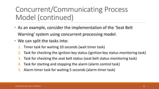
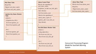
• As an example, consider the implementation of the 'Seat Belt
Warning' system using concurrent processing model.
• We can split the tasks into:
1. Timer task for waiting 10 seconds (wait timer task)
2. Task for checking the ignition key status (ignition key status monitoring task)
3. Task for checking the seat belt status (seat belt status monitoring task)
4. Task for starting and stopping the alarm (alarm control task)
5. Alarm timer task for waiting 5 seconds (alarm timer task)
91
Shrishail Bhat, Dept. of ECE, AITM Bhatkal
Concurrent/Communicating Process
Model (continued)
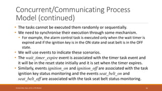
• The tasks cannot be executed them randomly or sequentially.
• We need to synchronise their execution through some mechanism.
• For example, the alarm control task is executed only when the wait timer is
expired and if the ignition key is in the ON state and seat belt is in the OFF
state.
• We will use events to indicate these scenarios.
• The wait_timer_expire event is associated with the timer task event and
it will be in the reset state initially and it is set when the timer expires.
• Similarly, events ignition_on and ignition_off are associated with the task
ignition key status monitoring and the events seat_belt_on and
seat_belt_off are associated with the task seat belt status monitoring.
92
Shrishail Bhat, Dept. of ECE, AITM Bhatkal
Concurrent/Communicating Process
Model (continued)
93
Shrishail Bhat, Dept. of ECE, AITM Bhatkal
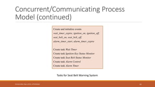
Create and initialize events
wait_timer_expire, ignition_on, ignition_off,
seat_belt_on, seat_belt_off,
alarm_timer_start, alarm_timer_expire
Create task Wait Timer
Create task Ignition Key Status Monitor
Create task Seat Belt Status Monitor
Create task Alarm Control
Create task Alarm Timer
Tasks for Seat Belt Warning System
94
Shrishail Bhat, Dept. of ECE, AITM Bhatkal
Wait Timer Task
Sleep(10s);
//Signal wait_timer_expire
Set Event wait_time_expire;
Concurrent Processing Program
Model for Seat Belt Warning
System
Ignition Key Status Monitor
Task
while(1) {
if (Ignition key ON) {
Set Event ignition_on;
Reset Event ignition_off;
}
else {
Set Event ignition_off;
Reset Event ignition_on;
}
}
Alarm Control Task
Wait for the signalling of
wait_timer_expire
if (ignition_on && seat_belt_off) {
Start Alarm();
Set Event alarm_start;
Wait for the signalling of
alarm_timer_expire or
ignition_off or seat_belt_on;
Stop Alarm();
}
Alarm Timer Task
Wait for the Event alarm_start;
Sleep(5s);
//Signal alarm_timer_expire
Set Event alarm_time_expire;
Seat Belt Status Monitor Task
while(1) {
if (Seat Belt ON) {
Set Event seat_belt_on;
Reset Event seat_belt_off;
}
else {
Set Event seat_belt_off;
Reset Event seat_belt_on;
}
}
Object-Oriented Model
• The object-oriented model is an object based model for modelling
system requirements.
• It disseminates a complex software requirement into simple well
defined pieces called objects.
• Object-oriented model brings re-usability, maintainability and
productivity in system design.
• In the object-oriented modelling, object is an entity used for
representing or modelling a particular piece of the system.
• Each object is characterised by a set of unique behaviour and state.
95
Shrishail Bhat, Dept. of ECE, AITM Bhatkal
Object-Oriented Model (continued)
• A class is an abstract description of a set of objects and it can be considered as
a 'blueprint' of an object.
• A class represents the state of an object through member variables and object
behaviour through member functions.
• The member variables and member functions of a class can be private, public
or protected.
• Private member variables and functions are accessible only within the class,
whereas public variables and functions are accessible within the class as well as
outside the class.
• The protected variables and functions are protected from external access.
• However classes derived from a parent class can also access the protected member
functions and variables.
• The concept of object and class brings abstraction, hiding and protection.
96
Shrishail Bhat, Dept. of ECE, AITM Bhatkal
Embedded Firmware
Design and
Development
97
Shrishail Bhat, Dept. of ECE, AITM Bhatkal
Introduction to Embedded Firmware
Design
• The embedded firmware is responsible for controlling the various
peripherals of the embedded hardware and generating response in
accordance with the functional requirements.
• Firmware is considered as the master brain of the embedded system.
• Imparting intelligence to an Embedded system is a one time process and
it can happen at any stage.
• It can be immediately after the fabrication of the embedded hardware or at a later
stage.
• For most of the embedded products, the embedded firmware is stored
at a permanent memory (ROM) and they are non-alterable by end users.
• Some of the embedded products used in the Control and Instrumentation domain
are adaptive.
98
Shrishail Bhat, Dept. of ECE, AITM Bhatkal
Introduction to Embedded Firmware
Design (continued)
• Designing embedded firmware requires understanding of the particular
embedded product hardware, like various component interfacing,
memory map details, I/O port details, configuration and register details
of various hardware chips used and some programming language.
• Embedded firmware development process starts with the conversion of
the firmware requirements into a program model using modelling tools.
• Once the program model is created, the next step is the implementation
of the tasks and actions by capturing the model using a language which
is understandable by the target processor/controller.
99
Shrishail Bhat, Dept. of ECE, AITM Bhatkal
Embedded Firmware Design Approaches
• The firmware design approaches for embedded product is purely
dependent on the complexity of the functions to be performed, the
speed of operation required, etc.
• Two basic approaches are used for embedded firmware design:
• Super Loop Based Approach (Conventional Procedural Based Design)
• Embedded Operating System (OS) Based Approach
100
Shrishail Bhat, Dept. of ECE, AITM Bhatkal