Types of conductors, line parameters, calculation of inductance and capacitance of single and double circuit transmission lines, three phase lines with bundle conductors. Skin effect and
proximity effect.
Types of conductors, line parameters, calculation of inductance and capacitance of single and double circuit transmission lines, three phase lines with bundle conductors. Skin effect and
proximity effect.
Electromagnetic induction class 10 ICSE.pptxnysa tutorial
Hello our respected institutions and faculties
if you want to buy Editable materials (6 to 12th/Foundation/JEE/NEET/CET) for your institution
Contact me ... 8879919898
*CBSE 6 TO 10 TOPICWISE PER CHAPTER 100 QUESTION WITH ANSWER MATHEMATICS & SCIENCE & SST (Biology,Physics,Chemistry & Social studies)* Editable ms word
# *Neet/JEE(MAINS) PCMB*
# *IIT ( advance) PCM*
# *CET (PCMB) level with Details solutions*
(All jee,neet,advance,cet mcq's Count 1 lakh 50k ) data of all subjects*
*TOPICWISE WISE DPP PCMB NEW PATTERN AVILABLE*
Or also study material for *neet and jee* and *foundation* new Material with solutions
Like
*👉🏽Foundation( Class 6th to 10th) Editable Material Latest Available 👇..*
1. VMC - All Subjects
2. Carrer Point(Kota) - All Subjects
3. Bansal Classes - All Subjects
4. Narayana - All Subjects
5. Mentors - All Subjects
6. Brilliants - All Subjects
7. Resonance - All Subjects
8. Motioniitjee - All Subjects
9. Rao(Kota) - All Subjects
10. Insight - All Subjects
11. Allen - All Subjects
12. FITJEE - All Subjects
13. Abhyas Gurukul - All Subject
14. Parth Ashram - All Subject
Many Other+++
*👉🏽All IIT-JEE & NEET Coachings Editable 📚Study Material Latest Available..👇🏼*
1. Narayana - PCMB
2. Etoos India - PCMB
3. Brilliant- PCM
4.Career Point(Kota) - PCMB
5. Bansal - PCMB
6. Resonance - PCMB
7. Sri Chaitanya - PCM
8. Aakash(Delhi) - PCMB
9. Fitjee - PCM
10. Mastermind - PCMB
11. Mentors - PCB
12. Allen - PCMB
13. Plancess - PCMB
14. VMC - PCM
15. Motioniitjee - PCM
16. Nishith - PCM
17. Arride (Kota) - PCM
18. Rao IIT Acad. - PCM
19. Pulse - PCB
20. Abhyas Gurukul - PCMB
21. Drona - PCMB
22. Active Site - PCMB
23. Vision - PCM
24. Parth Ashram - PCMB
25. Brainsmiths - PCM
26. Infinite - PCM
27. Ekalavya - PCM
28. Trick Based - PCM
...
& Many Other Institute Complete Material Available ++.. Also Editable Books 📚 Available
⬇️⬇️⬇️⬇️⬇️⬇️⬇️⬇️⬇️
👉 *Teaching Notes & PPTs (PCMB Editable) are Available in colourful*
**New material Exchange offer also available **
*Those who want Pls contact us...*
or also have {All Etoos, Akash(i-tutor) Digital, Allen, NeetPrep Digital, neuclion, Neuclius Education ,Plancess, SSC, Airforce, CAT, GATE IIT-JAM, NIMCET, IAS pre + mains (RAS Pre + Mains), UPTET,CTET,STET, vedio lacture *(also KG TO 12th Animated video Lecture Language English & Hindi)*} contact with us........👇
For Sample Massage me .
A Strategic Approach: GenAI in EducationPeter Windle
Artificial Intelligence (AI) technologies such as Generative AI, Image Generators and Large Language Models have had a dramatic impact on teaching, learning and assessment over the past 18 months. The most immediate threat AI posed was to Academic Integrity with Higher Education Institutes (HEIs) focusing their efforts on combating the use of GenAI in assessment. Guidelines were developed for staff and students, policies put in place too. Innovative educators have forged paths in the use of Generative AI for teaching, learning and assessments leading to pockets of transformation springing up across HEIs, often with little or no top-down guidance, support or direction.
This Gasta posits a strategic approach to integrating AI into HEIs to prepare staff, students and the curriculum for an evolving world and workplace. We will highlight the advantages of working with these technologies beyond the realm of teaching, learning and assessment by considering prompt engineering skills, industry impact, curriculum changes, and the need for staff upskilling. In contrast, not engaging strategically with Generative AI poses risks, including falling behind peers, missed opportunities and failing to ensure our graduates remain employable. The rapid evolution of AI technologies necessitates a proactive and strategic approach if we are to remain relevant.
Palestine last event orientationfvgnh .pptxRaedMohamed3
An EFL lesson about the current events in Palestine. It is intended to be for intermediate students who wish to increase their listening skills through a short lesson in power point.
Read| The latest issue of The Challenger is here! We are thrilled to announce that our school paper has qualified for the NATIONAL SCHOOLS PRESS CONFERENCE (NSPC) 2024. Thank you for your unwavering support and trust. Dive into the stories that made us stand out!
June 3, 2024 Anti-Semitism Letter Sent to MIT President Kornbluth and MIT Cor...Levi Shapiro
Letter from the Congress of the United States regarding Anti-Semitism sent June 3rd to MIT President Sally Kornbluth, MIT Corp Chair, Mark Gorenberg
Dear Dr. Kornbluth and Mr. Gorenberg,
The US House of Representatives is deeply concerned by ongoing and pervasive acts of antisemitic
harassment and intimidation at the Massachusetts Institute of Technology (MIT). Failing to act decisively to ensure a safe learning environment for all students would be a grave dereliction of your responsibilities as President of MIT and Chair of the MIT Corporation.
This Congress will not stand idly by and allow an environment hostile to Jewish students to persist. The House believes that your institution is in violation of Title VI of the Civil Rights Act, and the inability or
unwillingness to rectify this violation through action requires accountability.
Postsecondary education is a unique opportunity for students to learn and have their ideas and beliefs challenged. However, universities receiving hundreds of millions of federal funds annually have denied
students that opportunity and have been hijacked to become venues for the promotion of terrorism, antisemitic harassment and intimidation, unlawful encampments, and in some cases, assaults and riots.
The House of Representatives will not countenance the use of federal funds to indoctrinate students into hateful, antisemitic, anti-American supporters of terrorism. Investigations into campus antisemitism by the Committee on Education and the Workforce and the Committee on Ways and Means have been expanded into a Congress-wide probe across all relevant jurisdictions to address this national crisis. The undersigned Committees will conduct oversight into the use of federal funds at MIT and its learning environment under authorities granted to each Committee.
• The Committee on Education and the Workforce has been investigating your institution since December 7, 2023. The Committee has broad jurisdiction over postsecondary education, including its compliance with Title VI of the Civil Rights Act, campus safety concerns over disruptions to the learning environment, and the awarding of federal student aid under the Higher Education Act.
• The Committee on Oversight and Accountability is investigating the sources of funding and other support flowing to groups espousing pro-Hamas propaganda and engaged in antisemitic harassment and intimidation of students. The Committee on Oversight and Accountability is the principal oversight committee of the US House of Representatives and has broad authority to investigate “any matter” at “any time” under House Rule X.
• The Committee on Ways and Means has been investigating several universities since November 15, 2023, when the Committee held a hearing entitled From Ivory Towers to Dark Corners: Investigating the Nexus Between Antisemitism, Tax-Exempt Universities, and Terror Financing. The Committee followed the hearing with letters to those institutions on January 10, 202
How to Make a Field invisible in Odoo 17Celine George
It is possible to hide or invisible some fields in odoo. Commonly using “invisible” attribute in the field definition to invisible the fields. This slide will show how to make a field invisible in odoo 17.
TESDA TM1 REVIEWER FOR NATIONAL ASSESSMENT WRITTEN AND ORAL QUESTIONS WITH A...
electromagnetic induction
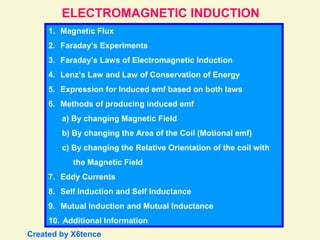
1. ELECTROMAGNETIC INDUCTION
1. Magnetic Flux
2. Faraday’s Experiments
3. Faraday’s Laws of Electromagnetic Induction
4. Lenz’s Law and Law of Conservation of Energy
5. Expression for Induced emf based on both laws
6. Methods of producing induced emf
a) By changing Magnetic Field
b) By changing the Area of the Coil (Motional emf)
c) By changing the Relative Orientation of the coil with
the Magnetic Field
7. Eddy Currents
8. Self Induction and Self Inductance
9. Mutual Induction and Mutual Inductance
10. Additional Information
Created by X6tence
2. Magnetic Flux (Φ):
Magnetic Flux through any surface is the number of magnetic lines of force
passing normally through that surface.
It can also be defined as the product of the area of the surface and the
component of the magnetic field normal to that surface.
θ
ds
n
B
B cos θ
dΦ = B . ds cos θ
Φ = B . A = B.A.n
Φ = B . A cos θ
Positive Flux:
Direction of ds is
along the normal to
the surface and
is unit normal
vector.
Magnetic Flux is positive for 0° ≤ θ < 90° &
270° < θ ≤ 360°
Zero Flux:
Magnetic Flux is zero for θ = 90° & θ = 270°
Negative Flux:
Magnetic Flux is negative for 90° < θ < 270°
n
dΦ = B . ds = B.ds.n
Flux is maximum
when θ = 0° and is
Φ = B . A
3. Φ = B . A cos θ
Magnetic Flux across a coil can be changed by changing :
1) the strength of the magnetic field B
2) the area of cross section of the coil A
3) the orientation of the coil with magnetic field θ or
4) any of the combination of the above
* Magnetic flux is a scalar quantity.
* SI unit of magnetic flux is weber or tesla-metre2 or ( wb or Tm2).
* cgs unit of magnetic flux is maxwell.
* 1 maxwell = 10-8 weber
* Magnetic flux (associated normally) per unit area is called Magnetic
Flux Density or Strength of Magnetic Field or Magnetic Induction (B).
4. S N N S
N S
Faraday’s Experiment - 1:
G
N S S N
S N
G
G G
5. S N
N S
G
Magnetic flux linked with the coil changes relative to the
positions of the coil and the magnet due to the magnetic lines of
force cutting at different angles at the same cross sectional area
of the coil.
6. Observe:
i) the relative motion between the coil and the magnet
ii) the induced polarities of magnetism in the coil
iii) the direction of current through the galvanometer and hence the
deflection in the galvanometer
iv) that the induced current (e.m.f) is available only as long as there is
relative motion between the coil and the magnet
Note: i) coil can be moved by fixing the magnet
ii) both the coil and magnet can be moved ( towards each other or
away from each other) i.e. there must be a relative velocity between
them
iii) magnetic flux linked with the coil changes relative to the positions
of the coil and the magnet
iv) current and hence the deflection is large if the relative velocity
between the coil and the magnet and hence the rate of change of
flux across the coil is more
7. Faraday’s Experiment - 2:
N S S N
E K
G
N S
E K
G
N S
When the primary circuit is closed
current grows from zero to
maximum value.
During this period changing,
current induces changing
magnetic flux across the primary
coil.
This changing magnetic flux is
linked across the secondary coil
and induces e.m.f (current) in the
secondary coil.
Induced e.m.f (current) and hence
deflection in galvanometer lasts
only as long as the current in the
primary coil and hence the
magnetic flux in the secondary
coil change.
P
P
S
S
8. When the primary circuit is open current decreases from maximum value to
zero.
During this period changing current induces changing magnetic flux across the
primary coil.
This changing magnetic flux is linked across the secondary coil and induces
current (e.m.f) in the secondary coil.
However, note that the direction of current in the secondary coil is reversed
and hence the deflection in the galvanometer is opposite to the previous case.
Faraday’s Laws of Electromagnetic Induction:
I Law:
Whenever there is a change in the magnetic flux linked with a circuit, an emf
and hence a current is induced in the circuit. However, it lasts only so long
as the magnetic flux is changing.
II Law:
The magnitude of the induced emf is directly proportional to the rate of
change of magnetic flux linked with a circuit.
E α dΦ / dt
E = k dΦ / dt
E = dΦ / dt E = (Φ2 – Φ1) / t
(where k is a constant and units are chosen such that k = 1)
9. Lenz’s Law:
The direction of the induced emf or induced current is such that it opposes
the change that is producing it.
i.e. If the current is induced due to motion of the magnet, then the induced
current in the coil sets itself to stop the motion of the magnet.
If the current is induced due to change in current in the primary coil, then
induced current is such that it tends to stop the change.
Lenz’s Law and Law of Conservation of Energy:
According to Lenz’s law, the induced emf opposes the change that produces
it. It is this opposition against which we perform mechanical work in causing
the change in magnetic flux. Therefore, mechanical energy is converted into
electrical energy. Thus, Lenz’s law is in accordance with the law of
conservation of energy.
If, however, the reverse would happen (i.e. the induced emf does not oppose
or aids the change), then a little change in magnetic flux would produce an
induced current which would help the change of flux further thereby
producing more current. The increased emf would then cause further change
of flux and it would further increase the current and so on. This would create
energy out of nothing which would violate the law of conservation of energy.
10. Expression for Induced emf based on both the laws:
E = - dΦ / dt
E = - (Φ2 – Φ1) / t
And for ‘N’ no. of turns of the coil,
E = - N dΦ / dt
E = - N (Φ2 – Φ1) / t
Expression for Induced current:
I = - dΦ / (R dt)
Expression for Charge:
dq / dt = - dΦ / (R dt)
dq = - dΦ / R
Note:
Induced emf does not depend on
resistance of the circuit where as
the induced current and induced
charge depend on resistance.
Methods of producing Induced emf:
1. By changing Magnetic Field B:
Magnetic flux Φ can be changed by changing the magnetic field B and
hence emf can be induced in the circuit (as done in Faraday’s
Experiments).
11. 2. By changing the area of the coil A available in Magnetic Field:
Magnetic flux Φ can be changed by changing the area of the loop A
which is acted upon by the magnetic field B and hence emf can be
induced in the circuit.
P’ Q’
P Q
S’ R’
v
I
S R
B
dA
l
v.dt
The loop PQRS is slided into uniform and perpendicular
magnetic field. The change (increase) in area of the coil
under the influence of the field is dA in time dt. This
causes an increase in magnetic flux dΦ.
dΦ = B.dA
= B.l.v.dt
E = - dΦ / dt
E = - Blv
The induced emf is due to motion of the loop and so it is called ‘motional emf’.
If the loop is pulled out of the magnetic field, then E = Blv
The direction of induced current is anticlockwise in the loop. i.e. P’S’R’Q’P’ by
Fleming’s Right Hand Rule or Lenz’s Rule.
12. According Lenz’s Rule, the direction of induced current is such that it
opposes the cause of changing magnetic flux.
Here, the cause of changing magnetic flux is due to motion of the loop and
increase in area of the coil in the uniform magnetic field.
Therefore, this motion of the loop is to be opposed. So, the current is setting
itself such that by Fleming’s Left Hand Rule, the conductor arm PS
experiences force to the right whereas the loop is trying to move to the left.
Against this force, mechanical work is done which is converted into electrical
energy (induced current).
NOTE: If the loop is completely inside the boundary of magnetic field, then
there will not be any change in magnetic flux and so there will not be induced
current in the loop.
Electric
Current
(I)
Force
(F)
Magnetic
Field
(B)
Fleming’s Right Hand Rule:
If the central finger, fore finger and thumb
of right hand are stretched mutually
perpendicular to each other and the fore
finger points to magnetic field, thumb
points in the direction of motion (force),
then central finger points to the direction of
induced current in the conductor.
13. 3. By changing the orientation of the coil (θ) in Magnetic Field:
Magnetic flux Φ can be changed by changing the relative orientation of the
loop (θ) with the magnetic field B and hence emf can be induced in the
circuit.
P
Q
S
θ B
R
ω
Φ = N B A cos θ
At time t, with angular velocity ω,
θ = ωt (at t = 0, loop is assumed to
be perpendicular to the magnetic field
and θ = 0°)
Φ = N B A cos ωt
Differentiating w.r.t. t,
dΦ / dt = - NBAω sin ωt
E = - dΦ / dt
E = NBAω sin ωt
E = E0 sin ωt (where E0 = NBAω is
the maximum emf)
n
14. The emf changes continuously in
magnitude and periodically in
direction w.r.t. time giving rise to
alternating emf.
If initial position of the coil is taken
as 0°, i.e. normal to the coil is at 90°
with the magnetic field, then
θ becomes θ + π/2 or ωt + π/2
E = E0 cos ωt
So, alternating emf and
consequently alternating current
can be expressed in sin or cos
function.
E
E0
T/4 T/2 3T/4 T 5T/4 3T/2 7T/4 2T
This method of inducing emf is the basic principle of generators.
t
0
π/2 π 3π/2 2π 5π/2 3π 7π/2 4πθ = ωt
E
E0
T/4 T/2 3T/4 T 5T/4 3T/2 7T/4 2T
t
0
π/2 π 3π/2 2π 5π/2 3π 7π/2 4πθ = ωt
15. Eddy Currents or Foucault Currents:
The induced circulating (looping) currents produced in a solid metal due to
change in magnetic field (magnetic flux) in the metal are called eddy currents.
B
Metallic Block Eddy Currents
Applications of Eddy Currents:
1. In induction furnace eddy currents are
used for melting iron ore, etc.
2. In speedometer eddy currents are used to
measure the instantaneous speed of the
vehicle.
3. In dead beat galvanometer eddy currents
are used to stop the damping of the coil
in a shorter interval.
4. In electric brakes of the train eddy currents are produced to stop the
rotation of the axle of the wheel.
5. In energy meters (watt – meter) eddy currents are used to measure the
consumption of electric energy.
6. In diathermy eddy currents are used for localised heating of tissues in
human bodies.
16. Self Induction:
Self Induction is the phenomenon of inducing emf in the self coil due to
change in current and hence the change in magnetic flux in the coil.
The induced emf opposes the growth or decay of current in the coil and
hence delays the current to acquire the maximum value.
Self induction is also called inertia of electricity as it opposes the growth or
decay of current.
Self Inductance:
Φ α I or Φ = LI
If I = 1, then L = Φ
(where L is the constant of proportionality and is known as
Self Inductance or co-efficient of self induction)
Thus, self inductance is defined as the magnetic flux linked with a coil
when unit current flows through it.
Also, E = - dΦ / dt or E = - L (dI / dt)
If dI / dt = 1, then L = E
Thus, self inductance is defined as the induced emf set up in the coil
through which the rate of change of current is unity.
17. SI unit of self inductance is henry (H).
Self inductance is said to be 1 henry when 1 A current in a coil links
magnetic flux of 1 weber.
or
Self inductance is said to be 1 henry when unit rate of change of current
(1 A / s) induces emf of 1 volt in the coil.
Self inductance of a solenoid:
l
A
I
Magnetic Field due to the solenoid is
B = μ0nI
Magnetic Flux linked across one turn of the
coil is
Φ per turn = B A = μ0nIA = μ0NIA / l
Magnetic Flux linked across N turns of the
coil is
Φ = μ0N2IA / l
But, Φ = LI
So, L = μ0N2A / l = μ0n2Al
Energy in Inductor:
Small work done dW in
establishing a current I in the
coil in time dt is dW = - EI dt
dW = LI dI (since E = -L(dI / dt)
I0
W = ∫ L I dI = ½ LI0
2
0
18. Mutual Induction:
Mutual Induction is the phenomenon of inducing emf in the secondary coil
due to change in current in the primary coil and hence the change in
magnetic flux in the secondary coil.
Mutual Inductance:
Φ21 α I1 or Φ21 = MI1
If I1 = 1, then M = Φ
(where M is the constant of proportionality and is
known as Mutual Inductance or co-efficient of mutual
induction)
Thus, mutual inductance is defined as the magnetic flux linked with the
secondary coil when unit current flows through the primary coil.
Also, E2 = - dΦ21 / dt or E 2= - M (dI1 / dt)
If dI1 / dt = 1, then M = E
Thus, mututal inductance is defined as the induced emf set up in the
secondary coil when the rate of change of current in primary coil is unity.
SI unit of mututal inductance is henry (H).
Mutual inductance is said to be 1 henry when 1 A current in the primary coil
links magnetic flux of 1 weber across the secondary coil. or
Mutual inductance is said to be 1 henry when unit rate of change of current
(1 A / s) in primary coil induces emf of 1 volt in the secondary coil.
19. Mutual inductance of two long co-axial solenoids:
Magnetic Field due to primary solenoid is
B1 = μ0n1I1
Magnetic Flux linked across one turn of the
secondary solenoid is
Φ21 per turn = B1 A = μ0n1I1A = μ0N1I1A / l
Magnetic Flux linked across N turns of the secondary
solenoid is
Φ21 = μ0N1N2I1A / l
But, Φ21 = M21I1
M21 = μ0N1N2A / l = μ0n1n2Al
lllly M12 = μ0N1N2A / l = μ0n1n2Al
A
For two long co-axial solenoids of same length and cross-sectional
area, the mutual inductance is same and leads to principle of
reciprocity.
M = M12 = M21
I1 l
G
P
S
20. Additional Information:
1) If the two solenoids are wound on a magnetic core of relative
permeability μr, then
M = μ0 μr N1N2A / l
2) If the solenoids S1 and S2 have no. of turns N1 and N2 of different radii r1
and r2 (r1 < r2), then
M = μ0 μr N1N2 (πr1
2)/ l
3) Mutual inductance depends also on the relative placement of the
solenoids.
4) Co-efficient of Coupling (K) between two coils having self-inductance L1
and L2 and mutual inductance M is
K = M / (√L1L2) Generally, K < 1
5) If L1 and L2 are in series, then L = L1 + L2
6) If L1 and L2 are in parallel, then (1/L) = (1/L1) + (1/L2)