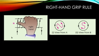
ELECTROMAGNETIC EFFECTS
PHYSICS YEAR 11
OBJECTIVES
By the end of this session, learner should be able to:
i. Describe the pattern of the magnetic field(including
direction) due to currents in straight wires and in
solenoids
ii. Describe the effect on the magnetic field of changing
the magnitude and direction of the current
KEY TERMS
• Solenoid
• Conductor
• Right-hand grip rule
• Oesterd’s experiment
• Magnetic field
1. Motors and generators.
2. Transformers.
3. Relays.
4. Electric bells and buzzers.
5. Loudspeakers and headphones.
6. Magnetic recording and data storage
equipment: tape recorders, VCRs,
hard disks.
7. MRI machines.
8. Maglev trains
OERSTED’S EXPERIMENT
• In 1819 Oersted accidentally discovered the magnetic effect of an electric
current.
• Introduction video.
• Magnetic effects of electric current Class 10.mp4
FIELD DUE TO A STRAIGHT WIRE
• When a current flows through a conductor, a magnetic field is
created around the conductor.
• The magnetic field around a straight wire is made up of
concentric circles perpendicular to the wire, with the wire in the
centre.
• You can see this by placing a compass near a wire that is
carrying a current. As you move the compass, it will trace the
direction of the magnetic field.
• The direction of the field is given by the right-hand grip rule:
If a straight conductor carrying current is held in the right hand
such that the thumb is pointed in the direction of the current,
then the direction in which your fingers encircle the wire gives
the direction of the magnetic lines of force around the wire.
FIELD DUE TO A STRAIGHT WIRE
1. The closer you get to the current-carrying wire, the stronger the magnetic field is.
This means that closer to the current-carrying wire, the magnetic field lines are
closer together
2. Increasing the size (magnitude) of the current makes the magnetic field stronger.
3. Changing the direction of the current changes the direction of the magnetic
field — use the right-hand grip rule to work out which way it goes.
A SOLENOID
1. If you wrap a current-carrying wire into a coil, it is called a solenoid.
2. Inside a solenoid, the magnetic field lines around each loop of wire line up with
each other. This results in lots of straight field lines pointing in the same direction,
therefore, the magnetic field inside the solenoid is strong and uniform.
3. Outside the solenoid, the magnetic field is just like the one round a bar magnet.
This means one end of the solenoid has a north pole and the other end has a
south pole.
RIGHT-HAND GRIP RULE
VARIATION OF MAGNETIC FIELD
STRENGTH
1. Magnetic field strength around a current-carrying straight wire becomes
less as the distance from the wire increases. Field lines becoming further
apart.
2. When the current through the wire is increased, the strength of the
magnetic field around the wire increases and the field lines become closer
together.
3. When the direction of the current changes, the magnetic field acts in the
opposite direction.
4. The magnetic field is stronger inside a solenoid than outside it.
5. When the direction of the current changes in the solenoid, the magnetic
field acts in the opposite direction.
6. The field inside a solenoid can be made very strong if it has a large number
of turns or a large current.
FORCE ON A CURRENT-CARRYING
CONDUCTOR
OBJECTIVES
By the end of this session, learner should be able to:
i. Describe an experiment to show that a force acts on a current-
carrying conductor in a magnetic field, including the effect of
reversing:
• the current
• the direction of the field
ii. State and use the relative directions of force, field and current
KEY TERMS
• Fleming's left-hand rule
INTRODUCTION
• Passing an electric current through a wire produces a magnetic field around
the wire.
• If you put that wire into a magnetic field, the two fields interact and a force is
exerted on the wire.
The motor effect
• A wire carrying a current in a magnetic field experiences a force. If the wire
can move, it does so.
DEMONSTRATION
• https://youtu.be/hYKPDxdEcT8?si=xvXzgeaKDbYtlpw_
1. When a current-carrying wire (or any other conductor) is put in a magnetic field,
the wire experiences a force. This can cause the wire to move and is called the
motor effect.
2. To experience the full force, the wire must be 90° to the magnetic field. If the wire
runs parallel to the magnetic field, it won’t experience any force. At angles in
between, it will experience some force.
3. The force always acts at right angles to the magnetic field of the magnets and the
direction of the current in the wire.
Reversing the direction of the current reverses the direction of the force.
Reversing the direction of the magnetic field (switching the positions of the north and
south poles) also causes the direction of the force to reverse.
FLEMING’S LEFT-HAND RULE
• You can find the direction of the force with
Fleming’s left-hand rule.
1. Using your left hand, point your First finger
in the direction of the Field.
2. Point your seCond finger in the direction of
the Current.
3. Your thuMb will then point in the direction
of the force (Motion).
THE D.C. MOTOR
OBJECTIVES
By the end of this lesson learners should be able to:
1. State that a current-carrying coil in a magnetic field experiences
a turning effect and that the effect is increased by:
 increasing the number of turns on the coil
 increasing the current
 increasing the strength of the magnetic field
2. Relate this turning effect to the action of an electric motor
including the action of a split-ring commutator
A CURRENT-CARRYING COIL OF
WIRE ROTATES IN A MAGNETIC FIELD
• Electric motors use the motor effect to get them moving (and to keep them
moving).
• A current-carrying conductor in a magnetic field experiences a force.
• If you twist a current-carrying wire into a coil and put it into a magnetic field,
the forces cause a turning effect.
• The turning effect on the coil is increased by:
1. Increasing the current in the coil
2. Increasing the number of turns on the coil
3. Increasing the strength of the magnetic field
The larger the turning effect on the coil, the faster it will turn.
SIMPLE D.C. ELECTRIC MOTOR
A simple d.c. motor consists of a rectangular coil of wire mounted on
an axle that can rotate between the poles of a C-shaped magnet.
Each end of the coil is connected to half of a split ring of copper,
called a split-ring commutator, which rotates with the coil.
Two carbon blocks, the brushes, are pressed lightly against the
commutator by springs. The brushes are connected to an electrical
supply.
If Fleming’s left-hand rule is applied to the coil, we find that side ab
experiences an upward force and side cd a downward force. (No
forces act on ad and bc since they are parallel to the field.)
These two forces produce a turning effect which rotates the coil in a
clockwise direction until it is vertical.
SIMPLE D.C. ELECTRIC MOTOR
The brushes are then in line with the gaps in the commutator and
the current stops.
However, because of its inertia, the coil overshoots the vertical and
the commutator halves change contact from one brush to the
other.
The current through the coil is reversed and so also the directions of
the forces on the sides.
Side ab is on the right now, acted on by a downward force, while
cd is on the left with an upward force.
The coil thus carries on rotating clockwise.
QUIZ
1. How would the turning effect on a current carrying coil in a magnetic field change if
i. the size of the magnetic field is increased
ii. the direction of the magnetic field is reversed?
2. In the simple d.c. electric motor of Figure 4.5.29, the coil rotates anticlockwise as
seen by the eye from the position X when current flows in the coil. Is the current
flowing clockwise or anticlockwise around the coil when viewed from above?
ELECTROMAGNETIC INDUCTION
OBJECTIVES
By the end of the lesson, learners should be able to:
1. Show understanding that a conductor moving across a
magnetic field or a changing magnetic field linking with
a conductor can induce an e.m.f. in the conductor.
2. State the factors affecting the magnitude of an induced
e.m.f.
EM INDUCTION
• Electromagnetic induction is the creation of an e.m.f. (and
a current if there’s a complete circuit) in a conductor that is
experiencing a change in a magnetic field or which is
moving relative to a magnetic field.
• Key terms
Induction
Coil
EM INDUCTION
•The effect of producing electricity from
magnetism was discovered in 1831 by Faraday
and is called electromagnetic induction.
•It led to the construction of generators for
producing electrical energy in power stations.
ELECTROMAGNETIC INDUCTION
EXPERIMENTS
•The effect of producing electricity from magnetism
was discovered in 1831 by Faraday and is called
electromagnetic induction.
•It led to the construction of generators for
producing electrical energy in power stations.
•Two ways of investigating electromagnetic
induction follow:
i. Straight wire and U-shaped magnet
ii. Bar magnet and coil
STRAIGHT WIRE AND U-SHAPED MAGNET
First the wire is held at rest between
the poles of the magnet.
It is then moved in each of the six
directions shown in Figure 4.5.1 and
the meter is observed.
Only when it is moving upwards
(direction1) or downwards (direction
2) is there a deflection on the meter,
indicating an induced current in the
wire.
The deflection is in opposite
directions in these two cases and
only lasts while the wire is in motion.
BAR MAGNET AND COIL
The magnet is pushed into the coil, one pole first
(Figure 4.5.2), then held still inside it.
It is then withdrawn.
The meter shows that current is induced in the
coil in one direction as the magnet is moved in
and in the opposite direction as it is moved out.
There is no deflection when the magnet is at
rest.
The results are the same if the coil is moved
instead of the magnet, i.e. only relative motion is
needed.
This experiment indicates that an e.m.f. is
induced in a conductor when it is linked by a
changing magnetic field or when it moves
across a magnetic field.
FACTORS AFFECTING THE MAGNITUDE OF AN INDUCED E.M.F.
E.m.f. increases with increases of
i. the speed of motion of the magnet or coil,
ii. the number of turns on the coil,
iii.the strength of the magnet
A.C. GENERATOR
OBJECTIVES
By the end of this lesson, learners should be able to:
1. Distinguish between direct current (d.c) and alternating current
(a.c)
2. Describe and explain the operation of a rotating coil generator
and the use of slip rings
3. Sketch a graph of voltage output against time for a simple a.c.
generator
A.C. GENERATOR
Key Terms
• Slip rings
• A.c.
• D.c.
• Frquency
ALTERNATING CURRENT VS DIRECT
CURRENT
1. Alternating current (a.c.) is a current that constantly changes
direction.
• Alternating current flows back and forth around a circuit — it
reverses its direction many times each second. It is produced
by an alternating potential difference in which the positive and
negative keep switching.
2. Direct current (d.c.) is a current that always flows in the same
direction.
• Direct current is created by a direct potential difference. Cells
and batteries supply d.c..
SIMPLE A.C. GENERATOR
• The simplest alternating current (a.c.) generator (alternator) consists
of a rectangular coil between the poles of a C-shaped magnet
(Figure 4.5.6a).
• The ends of the coil are joined to two slip rings on the axle and
against which carbon brushes press.
• When the coil is rotated it cuts the field lines and an e.m.f. is induced
in it.
• Figure 4.5.6b shows how the e.m.f. varies over one complete rotation.
• As the coil moves through the vertical position with ab uppermost, ab
and cd are moving along the lines (bc and da do so always), and no
cutting occurs.
• The induced e.m.f. is zero.
SIMPLE A.C. GENERATOR
• During the first quarter rotation the e.m.f. increases to a maximum
when the coil is horizontal.
• Sides ab and dc are then cutting the lines at the greatest rate.
• In the second quarter rotation the e.m.f. decreases again and is zero
when the coil is vertical with dc uppermost.
• After this, the direction of the e.m.f. reverses because, during the next
half rotation, the motion of ab is directed upwards and dc downwards.
• The frequency of an a.c. is the number of complete cycles it makes
each second and is measured in hertz (Hz), i.e. 1 cycle per second = 1
Hz.
• If the coil rotates twice per second, the a.c. has a frequency of 2Hz.
• The mains supply is a.c. of frequency 50Hz.
QUIZ
1. Which feature of the rotating coil of an a.c. generator
allows the induced e.m.f. to be connected to fixed
contacts?
2. a Sketch the output of an a.c. generator against time.
b At what position of the coil in an a.c. generator is the
output
i. a maximum
ii. zero?
STARTER QUIZ 2/3/2024
TRANSFORMER
OBJECTIVES
By the end of this lesson, learners should be able to:
1. Describe the construction of a basic transformer with a soft-iron core, as
used for voltage transformations
2. Describe the principle of operation of a transformer
3. Use the terms step-up and step-down
4. Recall and use the equation(Vp/Vs) = (Np/Ns) (for 100% efficiency)
5. Describe the use of the transformer in high-voltage transmission of electricity
6. Recall and use the equation IpVp = IsVs (for 100% efficiency)
7. Explain why power losses in cables are lower when the voltage is high
TRANSFORMER
Transformers are used to change the size of the voltage of an alternating electricity
supply.
They consist of two coils wound around a core made from soft iron.
An input voltage is applied across a primary coil.
This produces an output voltage across a secondary coil.
The primary and secondary coils, can either be on top of one another (Figure a) or
on separate limbs (Figure b).
TRANSFORMER
There are two types of transformer, step-up and step-down:
MUTUAL INDUCTION
When the current in a coil is switched on or off or changed in a
simple iron-cored transformer, a voltage is induced in a neighbouring
coil.
The effect, called mutual induction, is an example of
electromagnetic induction.
When an alternating voltage is applied across the primary coil, the
current that flows induces a changing magnetic field in the iron core.
Because the core is made from soft iron, it magnetises and
demagnetises quickly.
This changing magnetic field induces an alternating voltage in the
secondary coil. a.c. because a changing magnetic field is needed to
induce a voltage.
THE TRANSFORMER EQUATION
The ratio between the primary and secondary voltages is the same
as the ratio between the number of turns on the primary and
secondary coils.
You can calculate the output voltage of a transformer from the
input voltage and the number of turns on each coil.
=
THE TRANSFORMER SYMBOLS
QUIZ
1. The main function of a step-down transformer is to:
a) decrease current
b) decrease voltage
c) change a.c. to d.c.
d) change d.c. to a.c.
2. A transformer has 1000 turns on the primary coil. The voltage
applied to the primary coil is 230 V a.c. How many turns are on
the secondary coil if the output voltage is 46 V a.c.?
a) 20
b) 2000
c) 200
d) 4000
EXAM STYLE QUIZ
TRANSMISSION OF ELECTRICAL
POWER
TRANSMISSION OF ELECTRICAL
POWER
The National Grid is a network of cables, mostly supported on
pylons, that connects all the power stations in a country to
consumers.
The huge amounts of power are transmitted at a very high
voltage.
To get the electricity to this voltage, step-up transformers are used
between power stations and the transmission cables.
The voltage is then decreased to safe, usable levels once the
electricity has reached consumers. For this, step-down transformers
are used.
As the voltage is stepped up, the power remains at the same high
level but the current decreases.
ADVANTAGES OF HIGH-VOLTAGE
TRANSMISSION OF ELECTRICITY
1. Reducing the amount of thermal energy lost in the
transmission cables
2. Allowing wires with small cross-sectional areas to be used;
are cheaper and easier to handle than the thicker wires
required to carry large currents.
ENERGY LOSSES IN A TRANSFORMER
Transformers are almost 100% efficient.
This means you can assume that the input power equals the
output power.
Power is given by P = IV .
 So input power = output power can also be written as:
EXAMPLE
A transformer has a potential difference of 15 V and a current of
10 A in its secondary coil. The current in the transformer’s primary
coil is 25 A. Assuming the transformer is 100% efficient, calculate
the potential difference across the transformer’s primary coil.
QUIZ
1. A transformer steps down the mains supply from 230 V to 10 V to operate an
answering machine.
a) What is the turns ratio, of the transformer windings?
b) How many turns are on the primary if the secondary has 100 turns?
c) What is the current in the primary if the transformer is 100% efficient and
the current in the answering machine is 2 A?
2. A transformer is 100% efficient. The current in the primary is 0.05A when the
p.d. is 240 V. Calculate the current in the secondary where the p.d. is 12 V.
EXAM STYLE QUIZ

Electromagnetic effects PowerPoint Presentation

  • 1.
  • 2.
    OBJECTIVES By the endof this session, learner should be able to: i. Describe the pattern of the magnetic field(including direction) due to currents in straight wires and in solenoids ii. Describe the effect on the magnetic field of changing the magnitude and direction of the current
  • 3.
    KEY TERMS • Solenoid •Conductor • Right-hand grip rule • Oesterd’s experiment • Magnetic field 1. Motors and generators. 2. Transformers. 3. Relays. 4. Electric bells and buzzers. 5. Loudspeakers and headphones. 6. Magnetic recording and data storage equipment: tape recorders, VCRs, hard disks. 7. MRI machines. 8. Maglev trains
  • 4.
    OERSTED’S EXPERIMENT • In1819 Oersted accidentally discovered the magnetic effect of an electric current. • Introduction video. • Magnetic effects of electric current Class 10.mp4
  • 5.
    FIELD DUE TOA STRAIGHT WIRE • When a current flows through a conductor, a magnetic field is created around the conductor. • The magnetic field around a straight wire is made up of concentric circles perpendicular to the wire, with the wire in the centre. • You can see this by placing a compass near a wire that is carrying a current. As you move the compass, it will trace the direction of the magnetic field. • The direction of the field is given by the right-hand grip rule: If a straight conductor carrying current is held in the right hand such that the thumb is pointed in the direction of the current, then the direction in which your fingers encircle the wire gives the direction of the magnetic lines of force around the wire.
  • 7.
    FIELD DUE TOA STRAIGHT WIRE 1. The closer you get to the current-carrying wire, the stronger the magnetic field is. This means that closer to the current-carrying wire, the magnetic field lines are closer together 2. Increasing the size (magnitude) of the current makes the magnetic field stronger. 3. Changing the direction of the current changes the direction of the magnetic field — use the right-hand grip rule to work out which way it goes.
  • 8.
    A SOLENOID 1. Ifyou wrap a current-carrying wire into a coil, it is called a solenoid. 2. Inside a solenoid, the magnetic field lines around each loop of wire line up with each other. This results in lots of straight field lines pointing in the same direction, therefore, the magnetic field inside the solenoid is strong and uniform. 3. Outside the solenoid, the magnetic field is just like the one round a bar magnet. This means one end of the solenoid has a north pole and the other end has a south pole.
  • 9.
  • 10.
    VARIATION OF MAGNETICFIELD STRENGTH 1. Magnetic field strength around a current-carrying straight wire becomes less as the distance from the wire increases. Field lines becoming further apart. 2. When the current through the wire is increased, the strength of the magnetic field around the wire increases and the field lines become closer together. 3. When the direction of the current changes, the magnetic field acts in the opposite direction. 4. The magnetic field is stronger inside a solenoid than outside it. 5. When the direction of the current changes in the solenoid, the magnetic field acts in the opposite direction. 6. The field inside a solenoid can be made very strong if it has a large number of turns or a large current.
  • 11.
    FORCE ON ACURRENT-CARRYING CONDUCTOR OBJECTIVES By the end of this session, learner should be able to: i. Describe an experiment to show that a force acts on a current- carrying conductor in a magnetic field, including the effect of reversing: • the current • the direction of the field ii. State and use the relative directions of force, field and current
  • 12.
  • 13.
    INTRODUCTION • Passing anelectric current through a wire produces a magnetic field around the wire. • If you put that wire into a magnetic field, the two fields interact and a force is exerted on the wire. The motor effect • A wire carrying a current in a magnetic field experiences a force. If the wire can move, it does so.
  • 14.
    DEMONSTRATION • https://youtu.be/hYKPDxdEcT8?si=xvXzgeaKDbYtlpw_ 1. Whena current-carrying wire (or any other conductor) is put in a magnetic field, the wire experiences a force. This can cause the wire to move and is called the motor effect. 2. To experience the full force, the wire must be 90° to the magnetic field. If the wire runs parallel to the magnetic field, it won’t experience any force. At angles in between, it will experience some force. 3. The force always acts at right angles to the magnetic field of the magnets and the direction of the current in the wire. Reversing the direction of the current reverses the direction of the force. Reversing the direction of the magnetic field (switching the positions of the north and south poles) also causes the direction of the force to reverse.
  • 15.
    FLEMING’S LEFT-HAND RULE •You can find the direction of the force with Fleming’s left-hand rule. 1. Using your left hand, point your First finger in the direction of the Field. 2. Point your seCond finger in the direction of the Current. 3. Your thuMb will then point in the direction of the force (Motion).
  • 16.
    THE D.C. MOTOR OBJECTIVES Bythe end of this lesson learners should be able to: 1. State that a current-carrying coil in a magnetic field experiences a turning effect and that the effect is increased by:  increasing the number of turns on the coil  increasing the current  increasing the strength of the magnetic field 2. Relate this turning effect to the action of an electric motor including the action of a split-ring commutator
  • 17.
    A CURRENT-CARRYING COILOF WIRE ROTATES IN A MAGNETIC FIELD • Electric motors use the motor effect to get them moving (and to keep them moving). • A current-carrying conductor in a magnetic field experiences a force. • If you twist a current-carrying wire into a coil and put it into a magnetic field, the forces cause a turning effect. • The turning effect on the coil is increased by: 1. Increasing the current in the coil 2. Increasing the number of turns on the coil 3. Increasing the strength of the magnetic field The larger the turning effect on the coil, the faster it will turn.
  • 18.
  • 19.
    SIMPLE D.C. ELECTRICMOTOR A simple d.c. motor consists of a rectangular coil of wire mounted on an axle that can rotate between the poles of a C-shaped magnet. Each end of the coil is connected to half of a split ring of copper, called a split-ring commutator, which rotates with the coil. Two carbon blocks, the brushes, are pressed lightly against the commutator by springs. The brushes are connected to an electrical supply. If Fleming’s left-hand rule is applied to the coil, we find that side ab experiences an upward force and side cd a downward force. (No forces act on ad and bc since they are parallel to the field.) These two forces produce a turning effect which rotates the coil in a clockwise direction until it is vertical.
  • 20.
    SIMPLE D.C. ELECTRICMOTOR The brushes are then in line with the gaps in the commutator and the current stops. However, because of its inertia, the coil overshoots the vertical and the commutator halves change contact from one brush to the other. The current through the coil is reversed and so also the directions of the forces on the sides. Side ab is on the right now, acted on by a downward force, while cd is on the left with an upward force. The coil thus carries on rotating clockwise.
  • 21.
    QUIZ 1. How wouldthe turning effect on a current carrying coil in a magnetic field change if i. the size of the magnetic field is increased ii. the direction of the magnetic field is reversed? 2. In the simple d.c. electric motor of Figure 4.5.29, the coil rotates anticlockwise as seen by the eye from the position X when current flows in the coil. Is the current flowing clockwise or anticlockwise around the coil when viewed from above?
  • 22.
    ELECTROMAGNETIC INDUCTION OBJECTIVES By theend of the lesson, learners should be able to: 1. Show understanding that a conductor moving across a magnetic field or a changing magnetic field linking with a conductor can induce an e.m.f. in the conductor. 2. State the factors affecting the magnitude of an induced e.m.f.
  • 23.
    EM INDUCTION • Electromagneticinduction is the creation of an e.m.f. (and a current if there’s a complete circuit) in a conductor that is experiencing a change in a magnetic field or which is moving relative to a magnetic field. • Key terms Induction Coil
  • 24.
    EM INDUCTION •The effectof producing electricity from magnetism was discovered in 1831 by Faraday and is called electromagnetic induction. •It led to the construction of generators for producing electrical energy in power stations.
  • 25.
    ELECTROMAGNETIC INDUCTION EXPERIMENTS •The effectof producing electricity from magnetism was discovered in 1831 by Faraday and is called electromagnetic induction. •It led to the construction of generators for producing electrical energy in power stations. •Two ways of investigating electromagnetic induction follow: i. Straight wire and U-shaped magnet ii. Bar magnet and coil
  • 26.
    STRAIGHT WIRE ANDU-SHAPED MAGNET First the wire is held at rest between the poles of the magnet. It is then moved in each of the six directions shown in Figure 4.5.1 and the meter is observed. Only when it is moving upwards (direction1) or downwards (direction 2) is there a deflection on the meter, indicating an induced current in the wire. The deflection is in opposite directions in these two cases and only lasts while the wire is in motion.
  • 27.
    BAR MAGNET ANDCOIL The magnet is pushed into the coil, one pole first (Figure 4.5.2), then held still inside it. It is then withdrawn. The meter shows that current is induced in the coil in one direction as the magnet is moved in and in the opposite direction as it is moved out. There is no deflection when the magnet is at rest. The results are the same if the coil is moved instead of the magnet, i.e. only relative motion is needed. This experiment indicates that an e.m.f. is induced in a conductor when it is linked by a changing magnetic field or when it moves across a magnetic field.
  • 28.
    FACTORS AFFECTING THEMAGNITUDE OF AN INDUCED E.M.F. E.m.f. increases with increases of i. the speed of motion of the magnet or coil, ii. the number of turns on the coil, iii.the strength of the magnet
  • 29.
    A.C. GENERATOR OBJECTIVES By theend of this lesson, learners should be able to: 1. Distinguish between direct current (d.c) and alternating current (a.c) 2. Describe and explain the operation of a rotating coil generator and the use of slip rings 3. Sketch a graph of voltage output against time for a simple a.c. generator
  • 30.
    A.C. GENERATOR Key Terms •Slip rings • A.c. • D.c. • Frquency
  • 31.
    ALTERNATING CURRENT VSDIRECT CURRENT 1. Alternating current (a.c.) is a current that constantly changes direction. • Alternating current flows back and forth around a circuit — it reverses its direction many times each second. It is produced by an alternating potential difference in which the positive and negative keep switching. 2. Direct current (d.c.) is a current that always flows in the same direction. • Direct current is created by a direct potential difference. Cells and batteries supply d.c..
  • 32.
  • 33.
    SIMPLE A.C. GENERATOR •The simplest alternating current (a.c.) generator (alternator) consists of a rectangular coil between the poles of a C-shaped magnet (Figure 4.5.6a). • The ends of the coil are joined to two slip rings on the axle and against which carbon brushes press. • When the coil is rotated it cuts the field lines and an e.m.f. is induced in it. • Figure 4.5.6b shows how the e.m.f. varies over one complete rotation. • As the coil moves through the vertical position with ab uppermost, ab and cd are moving along the lines (bc and da do so always), and no cutting occurs. • The induced e.m.f. is zero.
  • 34.
  • 35.
    SIMPLE A.C. GENERATOR •During the first quarter rotation the e.m.f. increases to a maximum when the coil is horizontal. • Sides ab and dc are then cutting the lines at the greatest rate. • In the second quarter rotation the e.m.f. decreases again and is zero when the coil is vertical with dc uppermost. • After this, the direction of the e.m.f. reverses because, during the next half rotation, the motion of ab is directed upwards and dc downwards. • The frequency of an a.c. is the number of complete cycles it makes each second and is measured in hertz (Hz), i.e. 1 cycle per second = 1 Hz. • If the coil rotates twice per second, the a.c. has a frequency of 2Hz. • The mains supply is a.c. of frequency 50Hz.
  • 36.
    QUIZ 1. Which featureof the rotating coil of an a.c. generator allows the induced e.m.f. to be connected to fixed contacts? 2. a Sketch the output of an a.c. generator against time. b At what position of the coil in an a.c. generator is the output i. a maximum ii. zero?
  • 37.
  • 38.
  • 39.
    TRANSFORMER OBJECTIVES By the endof this lesson, learners should be able to: 1. Describe the construction of a basic transformer with a soft-iron core, as used for voltage transformations 2. Describe the principle of operation of a transformer 3. Use the terms step-up and step-down 4. Recall and use the equation(Vp/Vs) = (Np/Ns) (for 100% efficiency) 5. Describe the use of the transformer in high-voltage transmission of electricity 6. Recall and use the equation IpVp = IsVs (for 100% efficiency) 7. Explain why power losses in cables are lower when the voltage is high
  • 40.
    TRANSFORMER Transformers are usedto change the size of the voltage of an alternating electricity supply. They consist of two coils wound around a core made from soft iron. An input voltage is applied across a primary coil. This produces an output voltage across a secondary coil. The primary and secondary coils, can either be on top of one another (Figure a) or on separate limbs (Figure b).
  • 41.
    TRANSFORMER There are twotypes of transformer, step-up and step-down:
  • 42.
    MUTUAL INDUCTION When thecurrent in a coil is switched on or off or changed in a simple iron-cored transformer, a voltage is induced in a neighbouring coil. The effect, called mutual induction, is an example of electromagnetic induction. When an alternating voltage is applied across the primary coil, the current that flows induces a changing magnetic field in the iron core. Because the core is made from soft iron, it magnetises and demagnetises quickly. This changing magnetic field induces an alternating voltage in the secondary coil. a.c. because a changing magnetic field is needed to induce a voltage.
  • 43.
    THE TRANSFORMER EQUATION Theratio between the primary and secondary voltages is the same as the ratio between the number of turns on the primary and secondary coils. You can calculate the output voltage of a transformer from the input voltage and the number of turns on each coil. =
  • 44.
  • 45.
    QUIZ 1. The mainfunction of a step-down transformer is to: a) decrease current b) decrease voltage c) change a.c. to d.c. d) change d.c. to a.c. 2. A transformer has 1000 turns on the primary coil. The voltage applied to the primary coil is 230 V a.c. How many turns are on the secondary coil if the output voltage is 46 V a.c.? a) 20 b) 2000 c) 200 d) 4000
  • 46.
  • 47.
  • 48.
    TRANSMISSION OF ELECTRICAL POWER TheNational Grid is a network of cables, mostly supported on pylons, that connects all the power stations in a country to consumers. The huge amounts of power are transmitted at a very high voltage. To get the electricity to this voltage, step-up transformers are used between power stations and the transmission cables. The voltage is then decreased to safe, usable levels once the electricity has reached consumers. For this, step-down transformers are used. As the voltage is stepped up, the power remains at the same high level but the current decreases.
  • 49.
    ADVANTAGES OF HIGH-VOLTAGE TRANSMISSIONOF ELECTRICITY 1. Reducing the amount of thermal energy lost in the transmission cables 2. Allowing wires with small cross-sectional areas to be used; are cheaper and easier to handle than the thicker wires required to carry large currents.
  • 50.
    ENERGY LOSSES INA TRANSFORMER Transformers are almost 100% efficient. This means you can assume that the input power equals the output power. Power is given by P = IV .  So input power = output power can also be written as:
  • 51.
    EXAMPLE A transformer hasa potential difference of 15 V and a current of 10 A in its secondary coil. The current in the transformer’s primary coil is 25 A. Assuming the transformer is 100% efficient, calculate the potential difference across the transformer’s primary coil.
  • 52.
    QUIZ 1. A transformersteps down the mains supply from 230 V to 10 V to operate an answering machine. a) What is the turns ratio, of the transformer windings? b) How many turns are on the primary if the secondary has 100 turns? c) What is the current in the primary if the transformer is 100% efficient and the current in the answering machine is 2 A? 2. A transformer is 100% efficient. The current in the primary is 0.05A when the p.d. is 240 V. Calculate the current in the secondary where the p.d. is 12 V.
  • 53.

Editor's Notes

  • #27 https://youtu.be/3SP6l7S2Gs4?si=bnlSvvIK_XE9o14o
  • #28 We use Flemings right-hand rule to determine the direction of the current produced. Hold your right hand in a fist then spread out the thumb, first finger and second finger at right-angles with each other. Point 1st finger in the N-S direction, rotate your finger so that the thumb points in direction of movement of wire, then second finger points in the direction of the current.
  • #32 We use Flemings right-hand rule to determine the direction of the current produced. Hold your right hand in a fist then spread out the thumb, first finger and second finger at right-angles with each other. Point 1st finger in the N-S direction, rotate your finger so that the thumb points in direction of movement of wire, then second finger points in the direction of the current.
  • #37 X-N, Y-S: You need to use Fleming’s left hand rule for this. Point your thumb in the direction of the force (movement) and your second finger towards you, as the current is coming out of the page. Your first finger shows that the direction of the field is from left to right, so X must be a north pole and Y must be a south pole. Increase current in the coil/increase turns in the coil/increase strength of the magnet
  • #38 The coil and the magnetic field are moving relative to each other, so an e.m.f./potential difference is induced across the coil move the magnet out of the coil / move coil away from the magnet / insert the south pole of the magnet into the same end of the coil / insert the north pole of the magnet into the other end of the coil push the magnet into the coil more quickly / use a stronger magnet / add more turns per unit length of wire Zero / no reading
  • #46 A step-up transformer is used to increase the voltage of V electricity supplied by the power stations for transmission through cables [1 mark]. Step-down transformers are then used to bring the voltage of the supply back down to a safe level to be supplied to the consumer [1 mark]. s ÷ V p = N s ÷ N So, N s = (V s ÷ V p p ) × N N s p = (4.0 ÷ 12) × 15 = 5 turns [2 marks for correct answer, otherwise 1 mark for correct equation or substitution] I I I p s s × V p = I = V s × V # = IV p ps s 4.0 2.5 ×12 = 7.5 A [2 marks for correct answer, otherwise 1 mark for correct equation or substitution]
  • #53 A step-up transformer is used to increase the voltage of V electricity supplied by the power stations for transmission through cables [1 mark]. Step-down transformers are then used to bring the voltage of the supply back down to a safe level to be supplied to the consumer [1 mark]. s ÷ V p = N s ÷ N So, N s = (V s ÷ V p p ) × N N s p = (4.0 ÷ 12) × 15 = 5 turns [2 marks for correct answer, otherwise 1 mark for correct equation or substitution] I I I p s s × V p = I = V s × V # = IV p ps s 4.0 2.5 ×12 = 7.5 A [2 marks for correct answer, otherwise 1 mark for correct equation or substitution]