Download to read offline
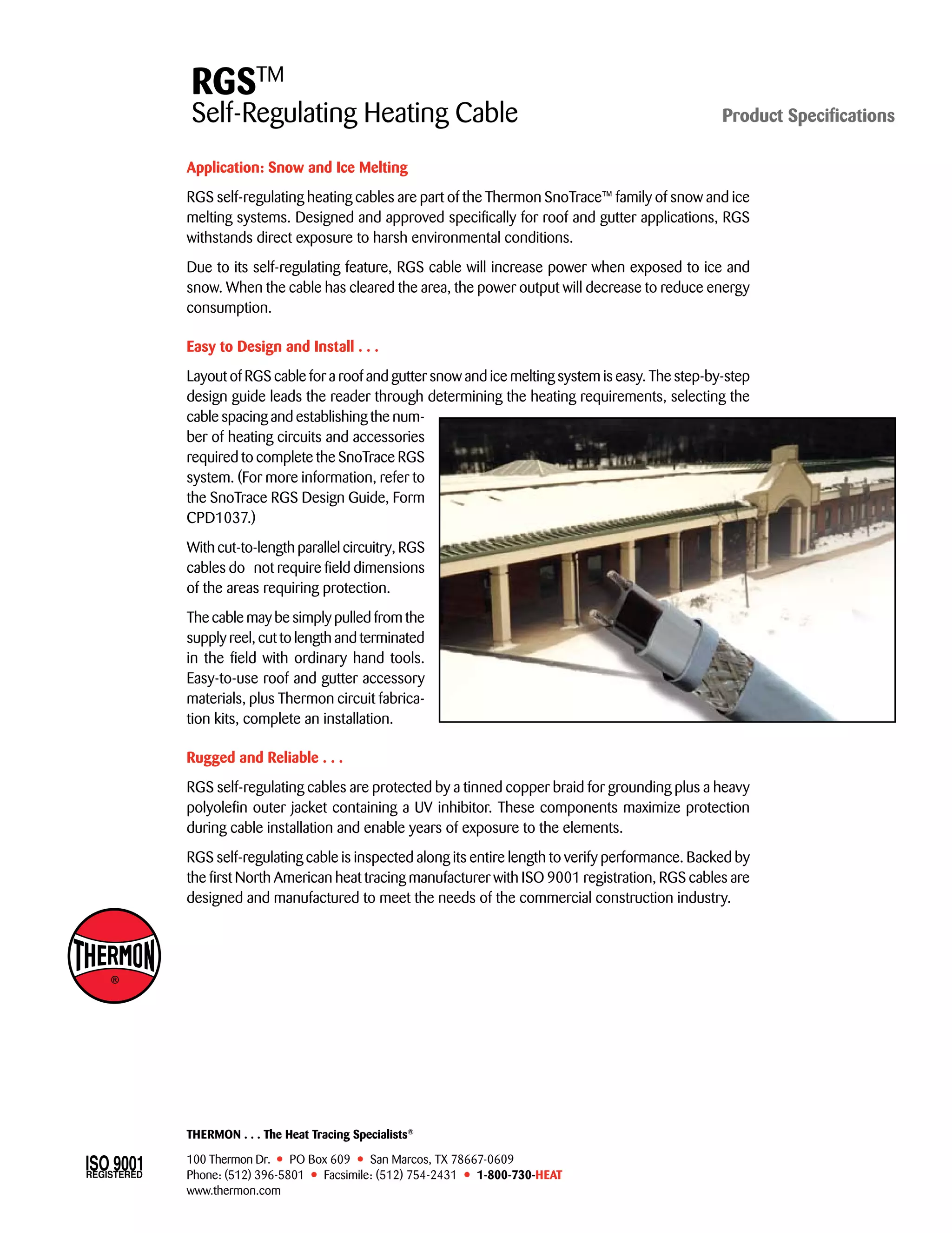


RGS self-regulating heating cables are designed for snow and ice melting applications on roofs and gutters. They increase power output when exposed to ice and snow, and decrease it once cleared to reduce energy consumption. The cables are easy to design, install, and cut to length on site using hand tools. They are rugged and reliable due to protective coatings that allow withstanding harsh environments for years.


