A three phase ups systems operating under nonlinear loads with modified spwm controller 29668
1. International Journal of Advance Engineering and Research
Development
Volume 2,Issue 9, September -2015
@IJAERD-2015, All rights Reserved 70
Scientific Journal of Impact Factor(SJIF): 3.134
e-ISSN(O): 2348-4470
p-ISSN(P): 2348-6406
A Three Phase UPS Systems Operating Under Nonlinear Loads with Modified
SPWM Controller
K. Srujan, Dr. S. Shiva Prasad, M. Vinod Kumar
1,2,3
Department of Electrical and Electronics Engineering,J.B Institute of Engineering & Technology ,Bhaskar
Nagar,R.R(Dist),Telangana
Abstract: -- This paper presents the design of a high-performance sinusoidal pulse width modulation (SPWM) controller
for three phase uninterruptible power supply (UPS) systems that are operating under highly nonlinear loads. The
classical SPWM method is quite effective in controlling the RMS magnitude of the UPS output voltages. However, it is
not good enough in compensating the harmonics and the distortion caused specifically by the nonlinear currents drawn
by the rectifier loads. The distortion becomes more severe at high power where the switching frequency has to be
reduced due to the efficiency concerns. This study proposes a new design strategy that overcomes the limitations of the
classical RMS control. It adds inner loops to the closed-loop control system effectively that enables successful reduction
of harmonics and compensation of distortion at the outputs. Simulink is used to analyze, develop, and design the
controller using the state-space model of the inverter. By using SPWM Controller THD of the system can be reduced
along with Magnitude of RMS voltage.
Keywords --- Uninterruptible power supply (UPS), nonlinear load, sinusoidal pulse width modulation (SPWM) control,
RMS Voltage, Total Harmonic Distortion (THD), MATLAB Simulink
I. INTRODUCTION
The increased use of rectifiers in critical loads employed by the information technologies, and medical and military
equipment mandate the design of uninterruptible power supplies (UPS) with high-quality outputs The highly nonlinear
currents drawn especially by high-power single-phase rectifier loads greatly distort the UPS outputs. The distorted UPS
voltages cause generation of low dc voltage at the output of the rectifier loads, which causes high current flow, increased
power losses, and possibly the malfunction of the critical load or the UPS. The distortion is resulted mainly by the
voltage drop across the inductive element of the LC filter due to the non-sinusoidal current at the output of the inverter.
In a UPS system, the inverter is responsible for synthesizing sinusoidal voltages froma dc source through the pulse width
modulation (PWM) of the dc voltage. The inductive element here is needed to remove the switching frequency
harmonics fromthe current waveform that are generated by the PWM operation of the inverter. The inductance value can
be reduced if the switching frequency is increased. But, in practice, it has an upper limit at high power inverters due to
the efficiency concerns and the switching device limitations. So, for the selected switching frequency and the power
level, an optimum filter with a smallest inductance can be designed, but the distortion cannot be completely avoided, and
the regulations and the customer specifications may not be satisfied. Despite several UPS topologies reported in
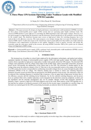
literature, Figure 1 present a high level UPS block diagram used in this work. Main aspects of this UPS topology are: i)
the load has two options to be directly powered, ii) DC power for the inverter stage is controlled on a rectifier stage, iii)
the load is an external agent for the UPS system, being in principle, an unknown factor for the inverter controller
Fig: 1. Functional Model of UPS
The main purpose of this study is to achieve a high power quality on inverter stage, thus a three-phase inverter circuit
2. International Journal of Advance Engineering and Research Development (IJAERD)
Volume 2,Issue 9, September -2015, e-ISSN: 2348 - 4470 , print-ISSN:2348-6406
@IJAERD-2015, All rights Reserved 71
1. DC voltage. From the inverter stage point of view, DC power can be considered perfectly controlled by the
rectifier stage. In this way, it could be represented as a battery bank.
2. DC/AC converter. This block describes a three-phase two level converter that will be triggered with a SPWM
scheme.
3. LC output filter. This second order low-pass filter is added to eliminate high switching frequency from the
DC/AC converter.
4. Output transformer. This block has several functions: i) offers a galvanic isolation for the load, ii) increases
synthesized voltage from the DC/AC converter to load voltage rating, iii) its leak impedance is used as part of
the output filter, iv) provides a neutral point to connect single phase loads. Static switch. This component allows
fast electrical switching between the alternative source and the voltage synthesized by the inverter
Nonlinear loads are shown in Figure 2 where nonlinear inductive and capacitive loads are presented in their three-
phase form. Nonlinear behavior is represented by a diode rectifier block, but could be an SCR or TRIAC as well. In these
cases normally an inductance is added in series to minimize input 𝑑 /𝑑𝑡.A nonlinear load represents a large harmonic
pollution for UPS inverter. This highly distorted current significantly affects the output-voltage waveform. In addition,
the capacitive nonlinear load produces a large current peak at connection when the capacitor is discharged. Pre-charge
schemes are usually implemented to avoid that as shown in Figure 2 allowing the capacitor to be charged through a
limited current.
Fig: 2 Non-linear loads, a) Inductive type, b) Capacitive type, c) Capacitive pre-charge circuit.
Pulse Width Modulation (PWM) is a popular technique used for controlling the width of the gate pulse by
various mechanisms. The DC-AC inverters usually operate on pulse width modulation technique (PWM). The traditional
inverter output voltage changes according to changes in the load. The PWM inverter irrespective of the output load keeps
the output voltage of the inverter at the rated voltage. The pulse width and switching frequency adjusted according to the
value of the load to provide constant rated output. SPWM are the most popular and widely used modulation techniques.
In SPWM the width of each pulse is varied in proportion to the amplitude of the sine Wave. The gating signals for the
inverter are generated by comparing a sinusoidal reference signal with a triangular wave carrier. It is obtained by taking
repeating sequence (triangular wave) as the control signal and comparing it with reference wave (sinusoidal signal). The
frequency and amplitude of the reference or modulating voltage is varied to get the desired output voltage.
II. BASIC OPERATION PRINCIPLE OF TYPICAL THREE-PHASE FOUR-WIRE TRANSFORMER
ISOLATED UPS SYSTEM
The single-line diagram of a typical three-phase four-wire transformer isolated UPS system is given in Fig. 3 The
three phase thyristor-based controlled rectifier converts the mains voltages into a constant dc and also provides
standalone charge to the batteries. Then, a six-switch PWM voltage source inverter (VSI) creates balanced three-phase
sinusoidal voltages across the load terminals at the utilization frequency and magnitude The LC low-pass filter removes
the harmonics generated by the PWM switching. The Δ-winding of the transformer blocks the third harmonic currents at
the inverter side, and the zigzag winding provides a neutral point and zero phase difference for the load -side voltages.
This section obtains the state-space model of the inverter stage of a three-phase UPS in order to design the controller for
the inverter. The developed model is also used to study the controller performance for the lowest THD of the output
voltage while maintaining the stability and a good dynamic response under all load conditions. The advantage of the
multi loop control system proposed here is that the loops can be optimized for the best performance relatively
independent of each other.
For example, the outer voltage loop is tuned first for the best voltage regulation, and then the inner loops can be
optimized relatively independently for the best THD of the output voltage while effectively managing and maintaining
the stability. Finally, the selection of the switching frequency is critically important in the elimination of the harmonics
and the distortion at the voltages. The high switching frequency allows a larger voltage loop bandwidth which enables
the controller to produce corrective actions to compensate for the fast changing oscillations at the voltage waveform
effectively.
3. International Journal of Advance Engineering and Research Development (IJAERD)
Volume 2,Issue 9, September -2015, e-ISSN: 2348 - 4470 , print-ISSN:2348-6406
@IJAERD-2015, All rights Reserved 72
Fig. 3 Single-line diagram of a typical three-phase four-wire transformer isolated UPS system.
The main criterion for assessing the quality of the voltage delivered by an inverter is the Total Harmonic
Distortion (THD). The goal is to see if the low order harmonics amplitude will decrease when the number of level
increases. The inverter is usually followed by a low pass filter since higher frequency harmonics are easy to filter. This
means that the performance of multilevel inverters can be improved by cancelling or reducing lower order harmonics.
Lower order harmonics generate the most important currents when an inductive load is used.
The THD is a ratio between the Root Mean Square (RMS) of the harmonics and the fundamental signal. For An
inverter that has a fundamental output voltage V1 and
Harmonics V2, V3,. . . , we define the THD as follows:
THD =
III. MATLAB/SIMULINK RESULTS OF MODIFIED SPWM CONTROLLER
Three phase UPS system has been simulated in MATLAB with Modified SPWM Controller .When the System is
operating with Nonlinear Loads by using Modified SPWM Controller it can generate the pulses and we can reduce the
output RMS Magnitude voltage Regulation and THD of the system.
Fig: 4. Matlab/Simulink Model for ModifiedSPWM Controller for Three Phase UPS Systems Operating Under
Nonlinear Loads
4. International Journal of Advance Engineering and Research Development (IJAERD)
Volume 2,Issue 9, September -2015, e-ISSN: 2348 - 4470 , print-ISSN:2348-6406
@IJAERD-2015, All rights Reserved 73
Fig: 5. Voltage & Current wave forms for Modified SPWM Controller for Three Phase UPS Systems Operating
under Nonlinear Loads
Fig: 6. Total Harmonic Distortion Voltage for ModifiedSPWM Controller for Three Phase UPS Systems
Operating Under Nonlinear Loads
Fig: 7 Fourier Magnitudes and Phase Voltage for Modified SPWM Controller for Three Phase UPS Systems
Operating Under Nonlinear Loads
5. International Journal of Advance Engineering and Research Development (IJAERD)
Volume 2,Issue 9, September -2015, e-ISSN: 2348 - 4470 , print-ISSN:2348-6406
@IJAERD-2015, All rights Reserved 74
Fig: 8. RMS Voltage for Modified SPWM Controller for Three Phase UPS Systems Operating Under Nonlinear
Loads
Fig: 9. Total Harmonic Distortion Current for Modified SPWM Controller for Three Phase UPS Systems
Operating Under Nonlinear Loads
Fig: 10. Fourier Magnitudes and Phase Current for Modified SPWM Controller for Three Phase UPS Systems
Operating Under Nonlinear Loads
6. International Journal of Advance Engineering and Research Development (IJAERD)
Volume 2,Issue 9, September -2015, e-ISSN: 2348 - 4470 , print-ISSN:2348-6406
@IJAERD-2015, All rights Reserved 75
Fig: 11. RMS Current for Modified SPWM Controller for Three Phase UPS Systems Operating Under Nonlinear
Loads
Fig: 12. THD of ModifiedSPWM Controller for Three Phase UPS Systems Operating Under Nonlinear Loads
IV. CONCLUSION
Therefore we can conclude that the design of a Modified SPWM controller for three-phase UPS systems powering
nonlinear loads. Although the classical SPWM method is very successful in controlling the RMS magnitude of the UPS
output voltages, it cannot effectively compensate for the harmonics and the distortion caused by the nonlinear currents
drawn by the rectifier loads. Therefore, this paper proposes a new strategy with a new design that overcomes the
limitations of the classical RMS control. A THD equal to 1 % at the output voltage is achieved even under the worst
nonlinear load. The load consists of three single-phase rectifiers connected between each line and the neutral and
absorbing power equal to the rated power of the UPS with a crest factor up to 3. The controller performance is evaluated
experimentally using a three phase 10 kVA transformer isolated UPS.A THD equal to 4.00% & 4.32% at output voltage
& current for SPWM is achieved.
REFERENCES
1. Uninterruptible power systems (UPS)—Part 3: Method of specifying the performance and test requirements, First
Edition 1999-03, International Standard IEC 62040-3.
2. F. Botter´on and H. Pinheiro, ―A three-phase UPS that complies with the standard IEC 62040-3,‖ IEEE Trans. Ind.
Electron., vol. 54, no. 4, pp.2120–2136, Aug. 2007.
3. Q.-C. Zhong and Y. Zeng, ―Can the output impedance of an inverter be designed capacitive?‖ in Proc. 37th Annu.
IEEE Conf. Ind. Electron., 2011, pp. 1220–1225.
4. U. Borup, P. N. Enjeti, and F. Blaabjerg, ―A new space-vector-based control method for UPS systems powering
nonlinear and unbalanced loads,‖IEEE Trans. Industry Appl., vol. 37, no. 6, pp. 1864–1870, Nov./Dec. 2001.
5. Q.-C. Zhong, F. Blaabjerg, J. Guerrero, and T. Hornik, ―Reduction of voltage harmonics for parallel-operated
inverters equipped with a robust droop controller,‖ in Proc. IEEE Energy Convers. Congr. Expo. Phoenix,AZ, 2011,
pp. 473–478.
6. S. Jiang, D. Cao, Y. Li, J. Liu, and F. Z. Peng, ―Low THD, fast transient,
And cost-effective synchronous-frame repetitive controller for three-phase UPS inverters,‖ IEEE Trans. Power
Electron., vol. 27, no. 6, pp. 2294–3005, 2012.
7. International Journal of Advance Engineering and Research Development (IJAERD)
Volume 2,Issue 9, September -2015, e-ISSN: 2348 - 4470 , print-ISSN:2348-6406
@IJAERD-2015, All rights Reserved 76
7. U. Borup, P. N. Enjeti, and F. Blaabjerg, ―A new space-vector bas control method for UPS systems powering
nonlinear and unbalanced loads,‖IEEE Trans. Industry Appl., vol. 37, no. 6, pp. 1864–1870, Nov./Dec. 2001.
8. K. Zhang, Y. Kang, J. Xiong, and J. Chen, ―Direct repetitive control of SPWM inverter for UPS purpose,‖ IEEE
Trans. Power Electron., vol. 18, no. 3, pp. 784–792, May 2003.
9. Y. Ye, K. Zhou, B. Zhang, D. Wang, and J. Wang, ―High-performance repetitive control of PWM DC-AC
converters with real-time phase-lead FIR filter,‖ IEEE Trans. Circuits Syst. II, Exp. Briefs, vol. 53, no. 8, pp. 768–
772, Aug. 2006.
10. BunyaminTamyurek, ―A High-Performance SPWM Controller for Three-Phase UPS Systems Operating under
Highly Nonlinear Loads‖ IEEE Trans. On power electronics, vol. 28, no. 8, pp3689–3701 august 2013.
BIOGRAPHIES
Srujan Kommera Received the B.Tech degree in Electrical and Electronics
Engineering from Joginpally B.R. Engineering College, India in 2012 and at present
Pursuing M.Tech with the Specialization of Electrical Power Systems in J.B. Institute
of Engineering & Technology, Bhaskar Nagar, Moinabad, R.R Dist. His area of
interest is Power Systems, Electric Drives and Multilevel Inverters.
Mondi Vinod Kumar received the B.Tech degree in Electrical & Electronics
Engineering from Vidya Jyothi Institute of Technology affiliated to JNTU Hyderabad
in 2004, the M.TECH degree in Electrical Power systems from J.B.Institute of
Engineering and Technology, Affiliated to JNTU Hyderabad, in 2008, he was
currently working as Assistant Professor at J.B.Institute of Engineering and
Technology, Affiliated to JNTU Hyderabad, India. His areas of interest include power
system.
Dr. S. Siva Prasad received Ph.D (Electrical) from JNTUH, Hyderabad. He received
M.Tech degree from JNTU, Hyderabad and B.Tech from SV University. He Currently
is working as a Professor and HOD in JB Institute of Engineering and Technology
(UGC Autonomous), Hyderabad, India. He received ―Bharat Vibhushan Samman
Puraskar‖ from ―The Economic and Human Resource Development Association‖ in
2013 and received Young Investigator Award in 2012. His research areas include
Power Electronics, Power Electronics & Drives, and Facts Controllers.