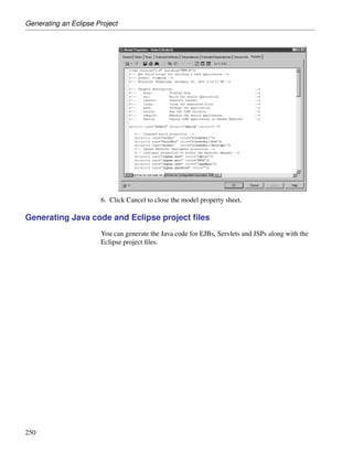
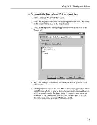
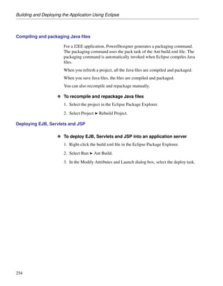
The document provides an introduction to working with the PowerDesigner Eclipse Plugin, explaining how to get started using the PowerDesigner interface within Eclipse, how to create and manage models and objects, and how to connect models to databases for reverse engineering and synchronization purposes. It outlines the key components of the PowerDesigner interface like the Model Explorer and property sheets and how to perform basic tasks like creating models, defining objects, and working with packages.


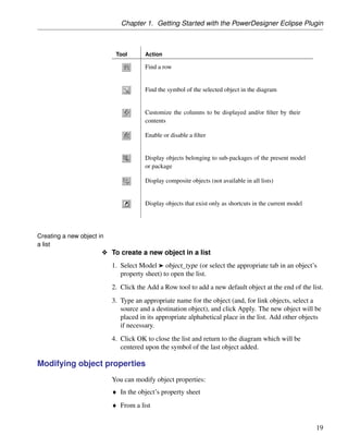
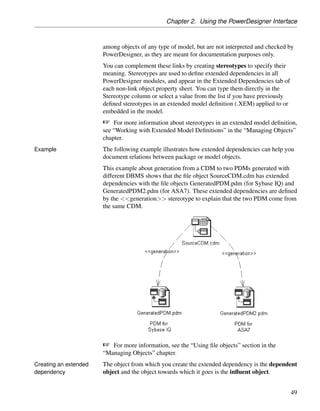
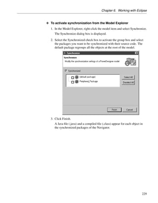
![Chapter 1. Getting Started with the PowerDesigner Eclipse Plugin
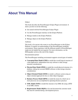
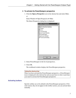
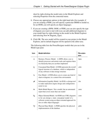
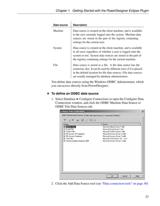
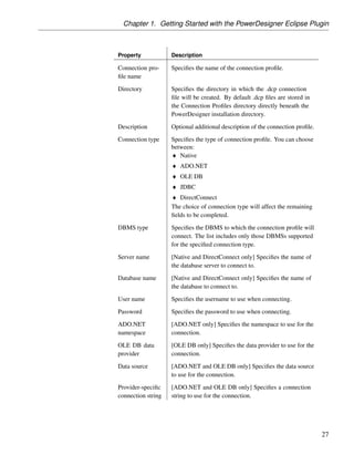
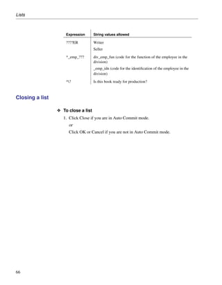
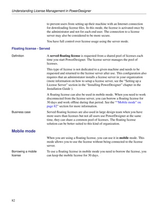
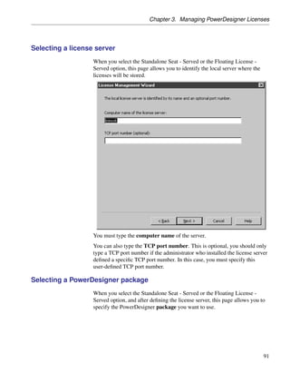
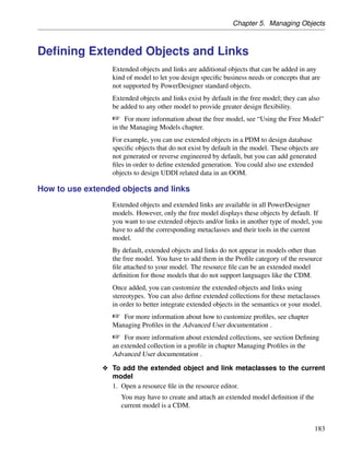
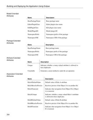
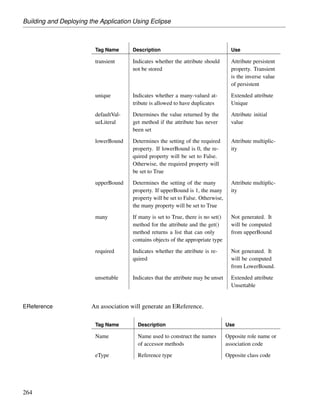
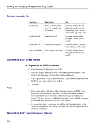
Property Description
Connection pro- Specifies the name of the connection profile.
file name
Directory Specifies the directory in which the .dcp connection
file will be created. By default .dcp files are stored in
the Connection Profiles directory directly beneath the
PowerDesigner installation directory.
Description Optional additional description of the connection profile.
Connection type Specifies the type of connection profile. You can choose
between:
♦ Native
♦ ADO.NET
♦ OLE DB
♦ JDBC
♦ DirectConnect
The choice of connection type will affect the remaining
fields to be completed.
DBMS type Specifies the DBMS to which the connection profile will
connect. The list includes only those DBMSs supported
for the specified connection type.
Server name [Native and DirectConnect only] Specifies the name of
the database server to connect to.
Database name [Native and DirectConnect only] Specifies the name of
the database to connect to.
User name Specifies the username to use when connecting.
Password Specifies the password to use when connecting.
ADO.NET [ADO.NET only] Specifies the namespace to use for the
namespace connection.
OLE DB data [OLE DB only] Specifies the data provider to use for the
provider connection.
Data source [ADO.NET and OLE DB only] Specifies the data source
to use for the connection.
Provider-specific [ADO.NET and OLE DB only] Specifies a connection
connection string string to use for the connection.
27](https://image.slidesharecdn.com/eclipsepluginuserguide-110617230622-phpapp02/85/Eclipse-plugin-userguide-38-320.jpg)
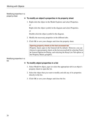
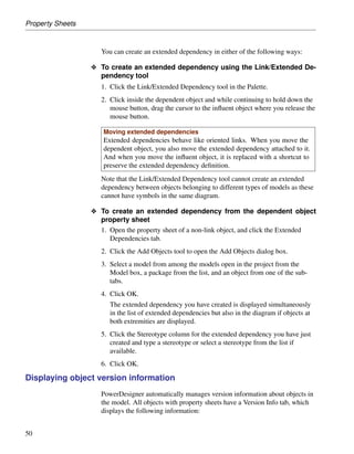
![Connecting to a Database
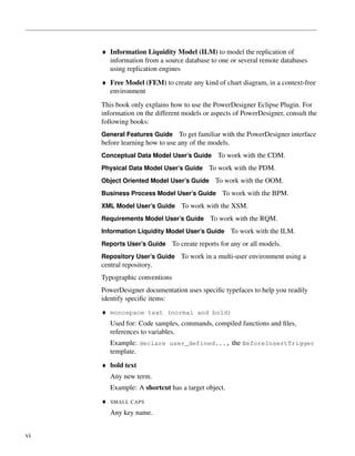
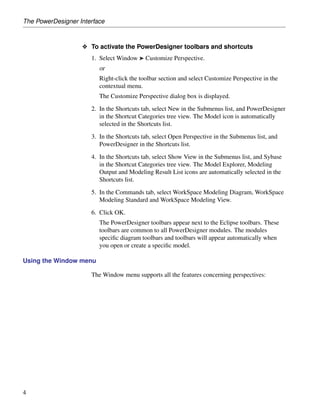
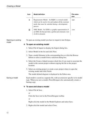
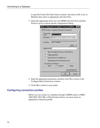
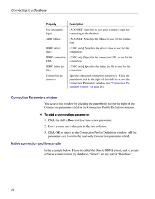
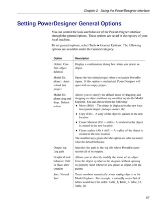
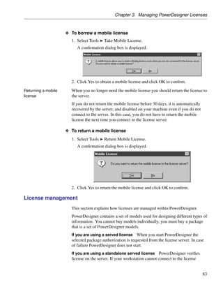
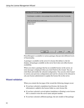
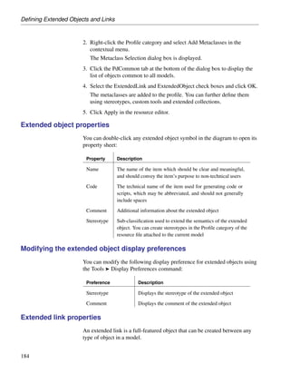
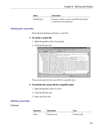
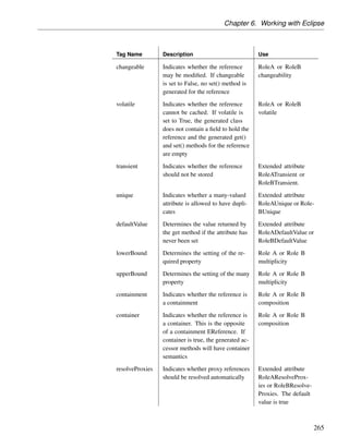
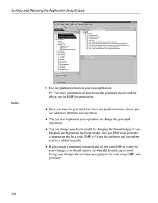
Property Description
Use integrated [ADO.NET] Specifies to use your windows login for
login connecting to the database.
ADO release [ADO.NET] Specifies the release to use for the connec-
tion.
JDBC driver [JDBC only] Specifies the driver class to use for the
class connection.
JDBC connection [JDBC only] Specifies the connection URL to use for the
URL connection.
JDBC driver jar [JDBC only] Specifies the driver jar file to use for the
files connection.
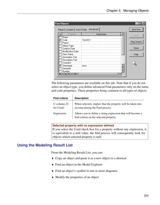
Connection pa- Specifies advanced connection parameters. Click the
rameters parenthesis tool to the right of this field to access the
Connection Parameters window (see “Connection Pa-
rameters window” on page 28).
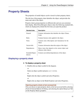
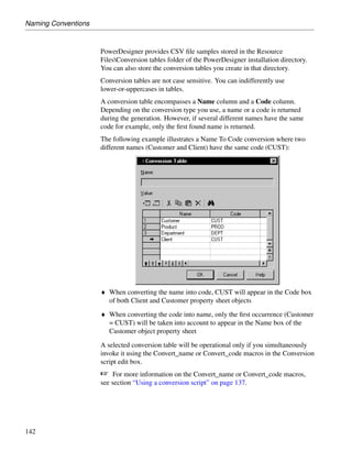
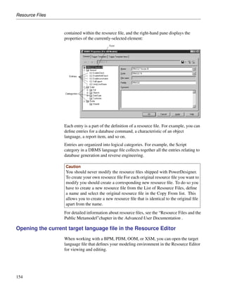
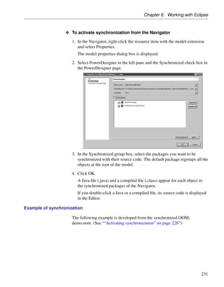
Connection Parameters window
You access this window by clicking the parenthesis tool to the right of the
Connection parameters field in the Connection Profile Definition window.
O To add a connection parameter
1. Click the Add a Row tool to create a new parameter.
2. Enter a name and value pair in the two columns.
3. Click OK to return to the Connection Profile Definition window. All the
parameters are listed in the read-only Connection parameters field.
Native connection profile example
In the example below, I have installed the Oracle DBMS client, and so create
a Native connection to my database, “Green”, on my server “Rainbow”.
28](https://image.slidesharecdn.com/eclipsepluginuserguide-110617230622-phpapp02/85/Eclipse-plugin-userguide-39-320.jpg)
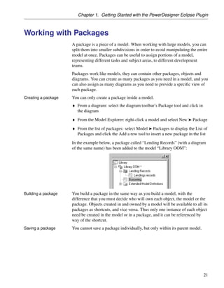
![Connecting to a Database
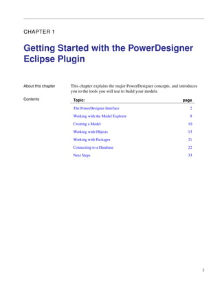
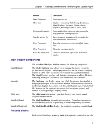
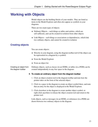
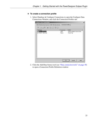
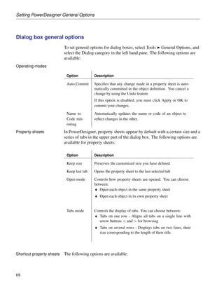
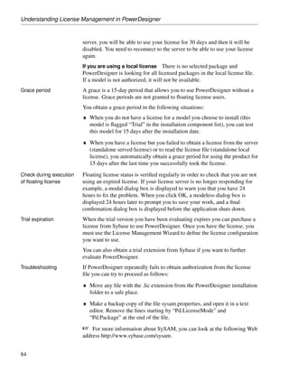
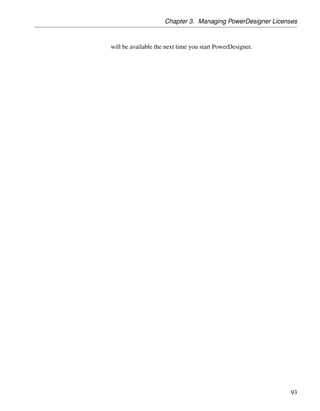
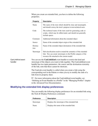
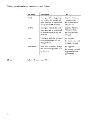
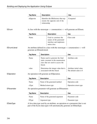
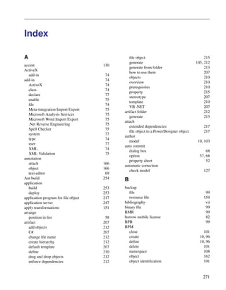
Data connection tools
The following tools are available in the Configure Data Connections
window:
Tool Description
Properties – Opens the ODBC Setup or Connection Profile Definition
dialog for the selected profile.
Add Data Source – Creates a new connection.
Browse Data Source File [ODBC file data sources and connection
profiles] – Opens a file browser to select a .dcp profile file.
Delete – Deletes the selected connection.
Test Connection – Tests the selected connection.
30](https://image.slidesharecdn.com/eclipsepluginuserguide-110617230622-phpapp02/85/Eclipse-plugin-userguide-41-320.jpg)
![Chapter 1. Getting Started with the PowerDesigner Eclipse Plugin
Tool Description
ODBC Administrator [ODBC machine and file data sources] –
Opens the ODBC Data Sources Administrator window.
Change Connection Profiles Directory [Connection profiles] – Opens
a file browser in which to search for profiles. The default directory is
install_dir/Connection Profiles.
Refresh – Refreshes the list of connections.
Select All – Selects all the connections in the list. Connections that
are selected will be displayed in lists in the PowerDesigner interface.
Unselect All - Unselects all the connections in the list. Connections
that are not selected will not be displayed in lists in the PowerDe-
signer interface.
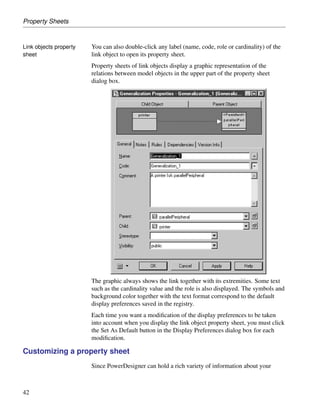
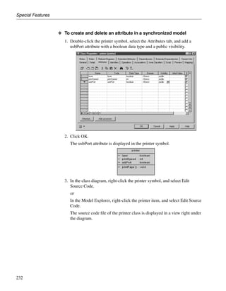
Connecting to a data source
When you connect to your database, PowerDesigner can communicate with
it for reverse-engineering, generation or any other form of request.
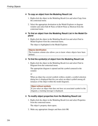
O To connect to a data source
1. Select Database ® Connect to open the Connect to a Data Source
window:
31](https://image.slidesharecdn.com/eclipsepluginuserguide-110617230622-phpapp02/85/Eclipse-plugin-userguide-42-320.jpg)
![Connecting to a Database
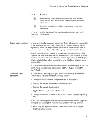
2. Select one of the following radio buttons, depending on your chosen
method for connecting to your data source:
♦ ODBC machine data source (see “Configuring ODBC machine and file
data sources” on page 22)
♦ ODBC file data source (see “Configuring ODBC machine and file data
sources” on page 22) - use the tool to the right of the data source field
to browse to a new file
♦ Connection profile (see “Configuring connection profiles” on page 24)
- use the tools to the right of the data source field to browse to a new
directory or file
You can use the Modify and Configure buttons to modify or configure
your connection.
3. Enter your user ID and password, and then click Connect. If prompted by
your data source, you may need to enter additional connection
parameters.
Connection time
You stay connected until you disconnect or terminate the shell session.
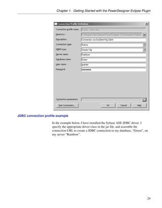
Running SQL queries against your database
You can use the Execute SQL Query dialog to query your database. The
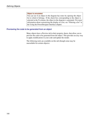
following tools are available in the Edit/Run Script editor toolbar:
Tool Description
Open Editor Contextual menu (SHIFT + F11)
Edit With (CTRL + E). Opens the previously defined default editor
(see “Defining a text editor” in the Using the PowerDesigner
Interface chapter). Click the down arrow to select another editor.
Run (F5). Executes the current script
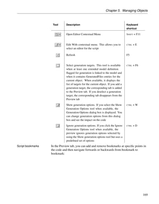
[n/a] Insert Bookmark (CTRL + F2) – inserts a blue bookmark box at the
cursor position. Press CTRL + F2 to delete the bookmark.
[n/a] Go to Next Bookmark (F2)
[n/a] Go to Previous Bookmark (SHIFT + F2)
32](https://image.slidesharecdn.com/eclipsepluginuserguide-110617230622-phpapp02/85/Eclipse-plugin-userguide-43-320.jpg)
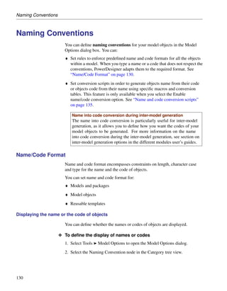
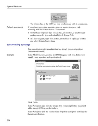
![Managing Objects in the Model Explorer
Managing Objects in the Model Explorer
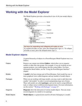
The Model Explorer is a powerful feature for navigating and managing
PowerDesigner objects.
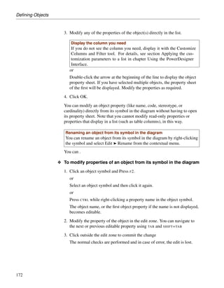
Creating an object in the Model Explorer
You can create objects in the Model Explorer. If the symbol of the new
object does not appear in the diagram you may have to select Symbol ®
Show Symbols and select the object check box in the Show Symbols dialog
box. Not all objects have symbols
O To create an object in the Model Explorer
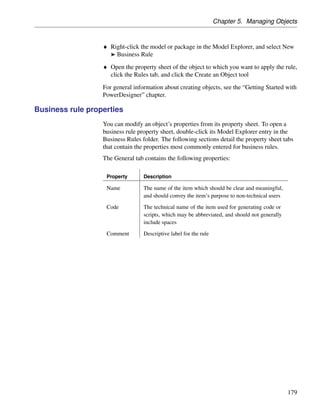
1. Right-click the project, a model, a package or an object folder and select
New ® object type to create the object and open its property sheet.
2. Type a name and a code for the object.
3. Click OK.
The object is displayed in the Model Explorer.
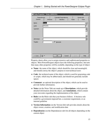
Object has a symbol
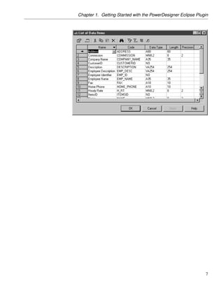
You can see if an object has a symbol in the diagram by opening the object
list to which it belongs and customize the display of the list so the S[ymbol]
column is displayed. If the check box in the S column corresponding to the
object is selected, then the object has a symbol in the diagram.](https://image.slidesharecdn.com/eclipsepluginuserguide-110617230622-phpapp02/85/Eclipse-plugin-userguide-47-320.jpg)
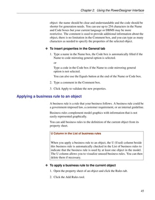
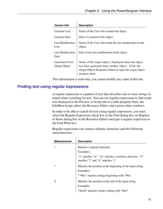
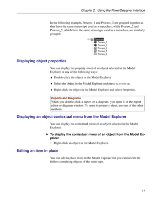
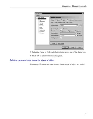
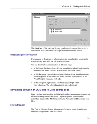
![Property Sheets
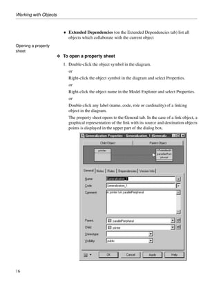
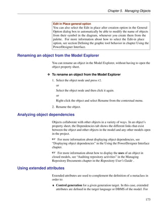
Metacharacter Description
* Matches the preceding character zero or more times
Examples:
”zo*” matches “z” and “zoo”
+ Matches the preceding character one or more times
Examples:
”zo+” matches “zo” and “zoo”, but not “z”
? Matches the preceding character zero or one time
Examples:
”to?” matches either “t” or “to”
. Matches any single character except the newline n
Examples:
”.ork” matches “Work”, “Fork” etc
[] Matches any one of the enclosed character
Examples:
”[abc]” matches “a”, “b”, or “c” A range of character can
be indicated with a dash “[a-z]”](https://image.slidesharecdn.com/eclipsepluginuserguide-110617230622-phpapp02/85/Eclipse-plugin-userguide-72-320.jpg)
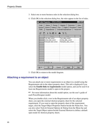
![Lists
Tool Description
Opens the property sheet of the selected item
[ordered lists only] Inserts a row before the selected row in the list
Adds a row at the end of the list
Opens an object selection dialog box to select objects and add them
to the list. When you select an item you copy it to the list.
Creates a new object and opens the corresponding property sheet
[CDM only] Opens an object selection dialog box to reuse objects.
When you select an item you create a link to the original item, you
do not copy it.
Deletes the row and stores it in the Clipboard
Copies the selected row to the Clipboard
Pastes the contents of the Clipboard
Deletes the row
Opens a Find dialog box to search an item in the list
Finds the symbol in the diagram
Opens a Filter dialog box to define a filter on the list
Enables the filter on the list
Includes objects in sub-packages in the list
56](https://image.slidesharecdn.com/eclipsepluginuserguide-110617230622-phpapp02/85/Eclipse-plugin-userguide-78-320.jpg)
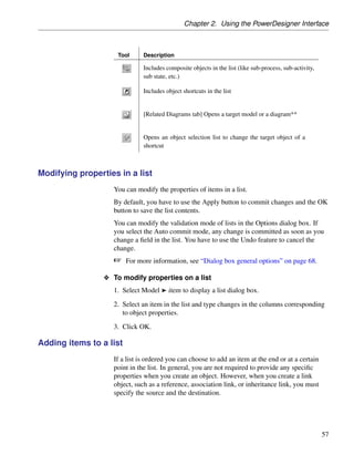
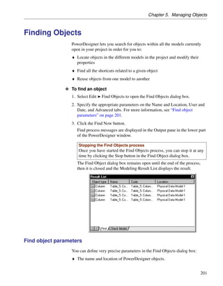
![Chapter 2. Using the PowerDesigner Interface
Tool Description
Includes composite objects in the list (like sub-process, sub-activity,
sub state, etc.)
Includes object shortcuts in the list
[Related Diagrams tab] Opens a target model or a diagram**
Opens an object selection list to change the target object of a
shortcut
Modifying properties in a list
You can modify the properties of items in a list.
By default, you have to use the Apply button to commit changes and the OK
button to save the list contents.
You can modify the validation mode of lists in the Options dialog box. If
you select the Auto commit mode, any change is committed as soon as you
change a field in the list. You have to use the Undo feature to cancel the
change.](https://image.slidesharecdn.com/eclipsepluginuserguide-110617230622-phpapp02/85/Eclipse-plugin-userguide-79-320.jpg)
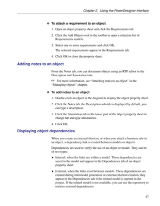
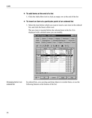
![Lists
Tool Description
- Owner List - [PDMs only] Lets you specify a user as the basis for
the list. The list will contain only objects owned by the specified
user or by no user. If you select User <NONE>, then all the
objects are displayed.
Include Sub-Packages - Includes objects contained in sub-
packages (Include Sub-Packages) in the list.
As this tool allows you to display all objects, regardless of their
package, some objects in the list may have the same name and be
difficult to identify. In this situation, you can use the Customize
Columns and Filter tool, to display the Object Location column
to identify where the objects are defined.
Include Composite-Objects - Includes composite objects, such as
sub-process, sub-activity, sub state, in the list
Include External Shortcuts - Includes shortcuts to objects in other
models in the list. The model containing the original objects must
be open for external shortcuts to be available for selection. When
generating, external shortcuts are generated as ordinary objects.
Select All - Selects all check boxes in the current object type tab.
To selects all check boxes in all object type tabs you can click the
arrow and select All Lists or you can press the CTRL key and click
the Select All tool.
Deselect All - Deselects all check boxes in the current object type
tab. To clear all check boxes in all object type tabs you can click
the arrow and select All Lists or you can press the CTRL key and
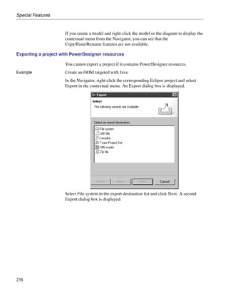
click the Deselect All tool.
Use Graphical Selection - Uses the graphical selection.
Move Selected Items to Top - Moves all selected objects to the
top of the list.
Move Selected Items to Bottom - Moves all selected objects to
the bottom of the list.
Customize Columns and Filter - Allows the definition of filter
expression on the columns of the selection list.
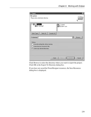
For more information about the Customize Columns and Filter
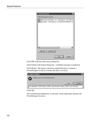
dialog box, see “Filtering a list” on page 64.
60](https://image.slidesharecdn.com/eclipsepluginuserguide-110617230622-phpapp02/85/Eclipse-plugin-userguide-83-320.jpg)

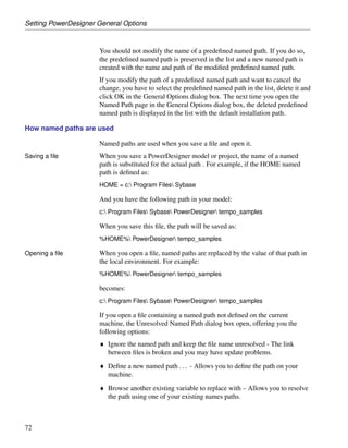
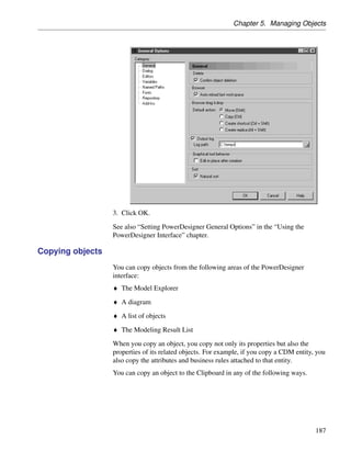
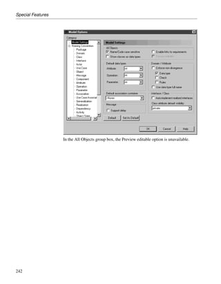
![Setting PowerDesigner General Options
used to edit files with this extension.
3. [optional] Enter an editor name (such as MS Word, Notepad, MS Excel)
in the Editor Name column, and enter an editor command (such as
winword.exe) in the Editor Command column. You can click the ellipsis
button in this field to browse to the relevant directory.
4. Click OK to close the dialog box.
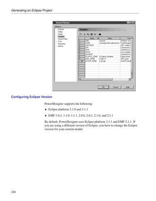
Defining environment variables
The following variables are created when you install PowerDesigner:
Variable Description Default
CMD Windows command interpreter command.com
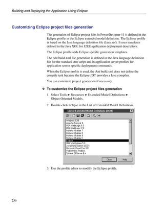
or cmd.exe
HOME Variable defining the default home directory —
J2EEVERIF Batch program for verifying if the deploy- verifier.bat
ment jar for an EJB is correct
JAR Command for archiving java files jar.exe
JAVA Command for running JAVA programs java.exe
JAVAC Command for compiling JAVA source files javac.exe
JAVADOC Command for defining JAVA doc comments javadoc.exe
You can edit these variables and add your own.
O To define an environment variable
1. Select Tools ® General Options, and click the Variables category in the
left-hand pane.
2. Click in the row of an existing variable in order to edit its values, or click
the Add a Row tool to create a new variable.
3. Click OK to close the dialog box.
Variables defined here are used in commands in the GenerationCommands
sub-category of the JAVA object language, and can be used in the Generation
Template Language.
The syntax for using these variables in GTL requires that you add $ before
the variable name within the % signs, for example %$CMD%.
70](https://image.slidesharecdn.com/eclipsepluginuserguide-110617230622-phpapp02/85/Eclipse-plugin-userguide-95-320.jpg)
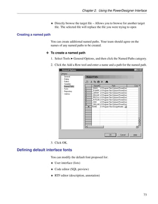
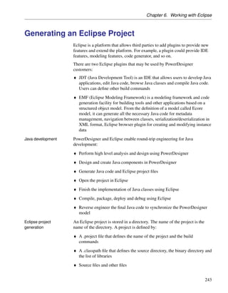
![Setting PowerDesigner General Options
.Net reverse engineering In order to use the .Net binary reverse, you need to register the application
reverseapp.exe.
.Net Framework 1.1 must be installed. You must use the regasm.exe
program located in the Windows directory under the
Microsoft.NETFramework folder. The command line is the following:
regasm /codebase reverseapp.exe
The .net Assemblies command is displayed in the File ® Reverse engineer
menu. The executable can also be used separately from PowerDesigner.
ReverseApp -c|-v [-l ] [-r ] [-g]
-l: followed by library file name, this option can be repeated several times.
-r: recursively forces to reverse engineer parameter type and return type.
-g: does not display reverse engineering dialog box and directly proceeds
with reverse engineering.
-c: reverse engineers C# model.
-v: reverse engineers VB.Net model.
ReverseApp will retrieve the namespaces, classes, and other objects defined
76](https://image.slidesharecdn.com/eclipsepluginuserguide-110617230622-phpapp02/85/Eclipse-plugin-userguide-102-320.jpg)
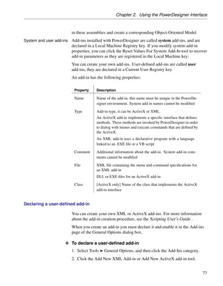
![Chapter 2. Using the PowerDesigner Interface
in these assemblies and create a corresponding Object-Oriented Model.
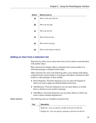
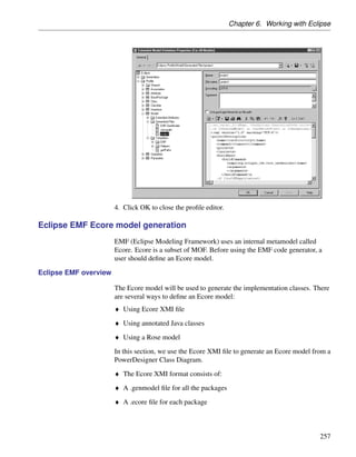
System and user add-ins Add-ins installed with PowerDesigner are called system add-ins, and are
declared in a Local Machine Registry key. If you modify system add-in
properties, you can click the Reset Values For System Add-In tool to recover
add-in parameters as they are registered in the Local Machine key:
You can create your own add-ins. User-defined add-ins are called user
add-ins, they are declared in a Current User Registry key.
An add-in has the following properties:
Property Description
Name Name of the add-in, this name must be unique in the PowerDe-
signer environment. System add-in names cannot be modified
Type Add-in type, it can be ActiveX or XML.
An ActiveX add-in implements a specific interface that defines
methods. These methods are invoked by PowerDesigner in order
to dialog with menus and execute commands that are defined by
the ActiveX.
An XML add-in uses a declarative program with a language
linked to an .EXE file or a VB script
Comment Additional information about the add-in. System add-in com-
ments cannot be modified
File XML file containing the menu and command specifications for
an XML add-in
DLL or EXE files for an ActiveX add-in
Class [ActiveX only] Name of the class that implements the ActiveX
add-in interface
Declaring a user-defined add-in
You can create your own XML or ActiveX add-ins. For more information
about the add-in creation procedure, see the Scripting User’s Guide .
When you create an add-in you must declare it and enable it in the Add-ins
page of the General Options dialog box.
O To declare a user-defined add-in
1. Select Tools ® General Options, and then click the Add-Ins category.
2. Click the Add New XML Add-in or Add New ActiveX add-in tool.
77](https://image.slidesharecdn.com/eclipsepluginuserguide-110617230622-phpapp02/85/Eclipse-plugin-userguide-103-320.jpg)
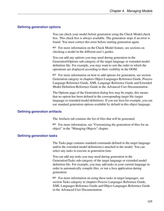
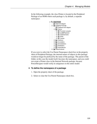
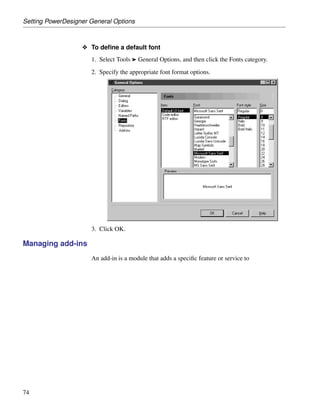
![Chapter 4. Managing Models
O To open a model which is closed in the project
1. Right-click the model node and select Open from the model contextual
menu.
You can open a model as read-only when you do not need to modify its
content.
O To open a model as read-only
1. Select File ® Open and select the Open as read-only check box in the
Open dialog box.
or
Right-click a model closed in the project and select Open As Read-only
in the contextual menu.
The model opens with (Read-only) specified in the title bar.
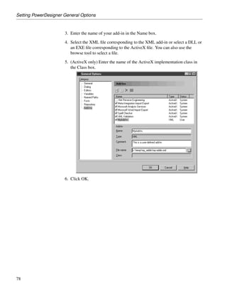
Saving a model When a model contains unsaved changes, an asterisk is appended to its name
in the Model Explorer.
When you save a model or a multi-model report, PowerDesigner
automatically assigns to the file a unique identifying number called GUID
(Global Unique ID), and creates a backup copy of your file with the same
identifying number. The GUID is used:
♦ In the Repository, to allow documents to be identified and updated
♦ During model generation
The following formats are available when you save a model:
Format Description
XML [default] The saving and loading time is longer (1.5x) than
binary, and the file size is bigger (2.5x) than binary.
You can open and modify the contents of an XML model file.
XML is recommended for small models.
Binary Saving and loading time is shorter than XML, and the file size is
smaller than XML
Recommended for big models.
99](https://image.slidesharecdn.com/eclipsepluginuserguide-110617230622-phpapp02/85/Eclipse-plugin-userguide-129-320.jpg)
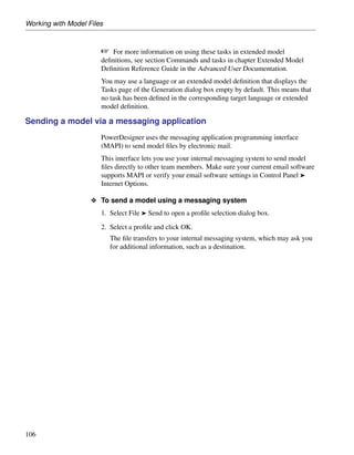
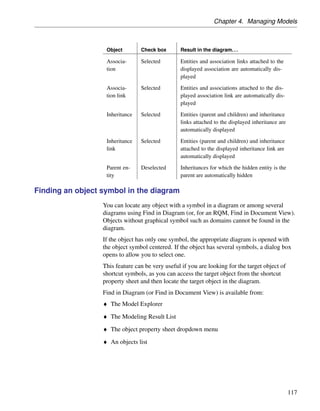
![For more information on shortcut creation, see the Managing Shortcuts
chapter.
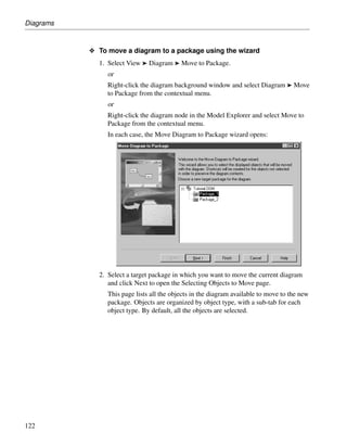
O To convert a diagram to a package
1. Select View ® Diagram ® Convert to Package.
or
Right-click the diagram background window and select Diagram ®
Convert to Package from the contextual menu.
or
Right-click the diagram node in the Model Explorer and select Convert to
Package from the contextual menu.
In each case, the Convert Diagram to Package wizard opens. By default
the sub-package takes the name of the diagram.
2. [optional] Enter a different name and code for the new package.
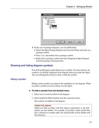
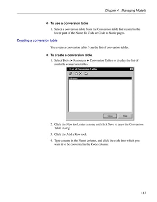
3. Click Next to open the Selecting Objects to Move page.
This page lists all the objects in the diagram available to move to the new
package. Objects are organized by object type, with a sub-tab for each
object type. By default, all the objects are selected.
120](https://image.slidesharecdn.com/eclipsepluginuserguide-110617230622-phpapp02/85/Eclipse-plugin-userguide-164-320.jpg)
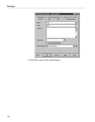
![Chapter 4. Managing Models
4. [optional] Deselect any objects you do not want to move to the new
package. Objects deselected here will remain in the original package and
be represented in the new package via shortcuts.
5. Click Finish to create the new package and move the selected objects to it.
The new package and diagram are added in the Model Explorer.
Moving a diagram to a package
In some cases, you may want to move a diagram and some or all of the
objects it contains into another package (or composite object such as process
or activity).
The linking objects that you move with the diagram keep their links in the
target package and a shortcut is usually created in the source package. The
general rule being that the design of the original diagram must be preserved.
Shortcut creation rules in PowerDesigner also apply to moving objects
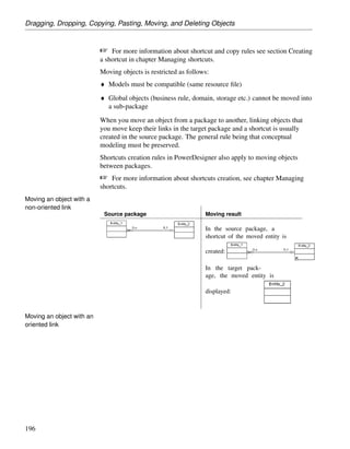
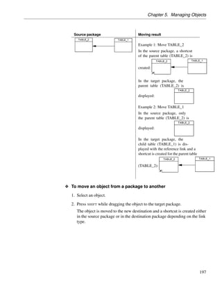
between packages.](https://image.slidesharecdn.com/eclipsepluginuserguide-110617230622-phpapp02/85/Eclipse-plugin-userguide-165-320.jpg)
![Chapter 4. Managing Models
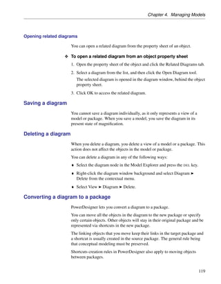
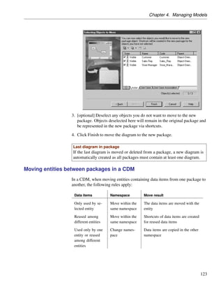
3. [optional] Deselect any objects you do not want to move to the new
package. Objects deselected here will remain in the original package and
be represented in the new package via shortcuts.
4. Click Finish to move the diagram to the new package.
Last diagram in package
If the last diagram is moved or deleted from a package, a new diagram is
automatically created as all packages must contain at least one diagram.
Moving entities between packages in a CDM
In a CDM, when moving entities containing data items from one package to
another, the following rules apply:
Data items Namespace Move result
Only used by se- Move within the The data items are moved with the
lected entity same namespace entity
Reused among Move within the Shortcuts of data items are created
different entities same namespace for reused data items
Used only by one Change names- Data items are copied in the other
entity or reused pace namespace
among different
entities
123](https://image.slidesharecdn.com/eclipsepluginuserguide-110617230622-phpapp02/85/Eclipse-plugin-userguide-168-320.jpg)
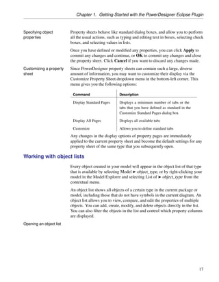
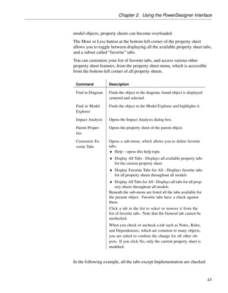
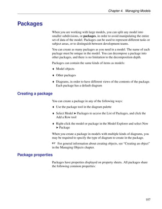
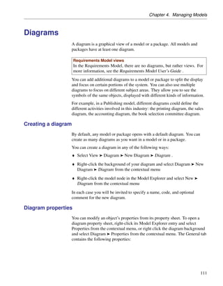
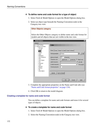
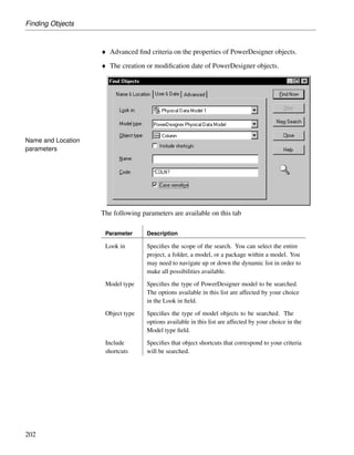
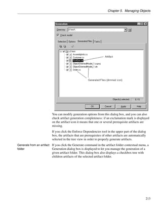
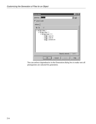
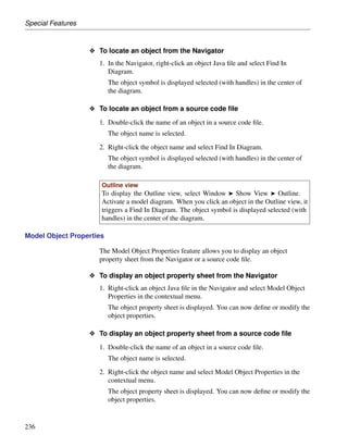
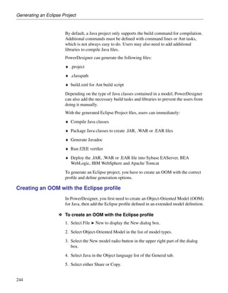
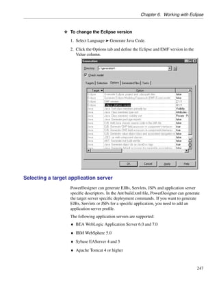
![Checking a Model
Checking a Model
You can check the validity of your model at any time. We recommend that
you check your model before generating code or another model from it. The
Check model option is enabled by default in the Generate dialog box and, if
an error is found, the generation is stopped.
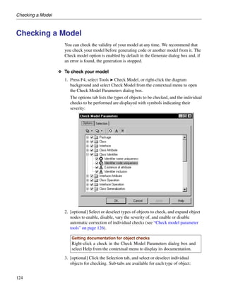
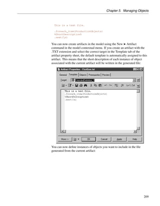
O To check your model
1. Press F4, select Tools ® Check Model, or right-click the diagram
background and select Check Model from the contextual menu to open
the Check Model Parameters dialog box.
The options tab lists the types of objects to be checked, and the individual
checks to be performed are displayed with symbols indicating their
severity:
2. [optional] Select or deselect types of objects to check, and expand object
nodes to enable, disable, vary the severity of, and enable or disable
automatic correction of individual checks (see “Check model parameter
tools” on page 126).
Getting documentation for object checks
Right-click a check in the Check Model Parameters dialog box and
select Help from the contextual menu to display its documentation.
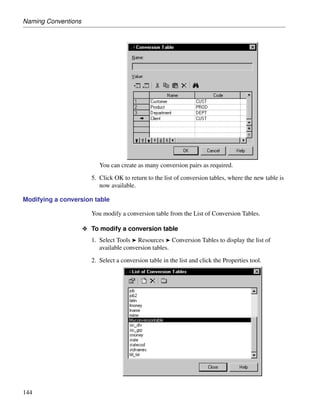
3. [optional] Click the Selection tab, and select or deselect individual
objects for checking. Sub-tabs are available for each type of object:
124](https://image.slidesharecdn.com/eclipsepluginuserguide-110617230622-phpapp02/85/Eclipse-plugin-userguide-169-320.jpg)
![Chapter 4. Managing Models
Selecting objects in the diagram
If you have selected object symbols in your diagram before starting
the model check, you can select them for checking by clicking the Use
Graphical Selection tool in the Selection tab tool bar.
For more information about selecting objects in Selection tabs, see the
“Adding an item from a selection list” section in the “Using the
PowerDesigner Interface” chapter.
4. [optional] Click Apply to save your selections so that they will be
available for future model checks.
5. Click OK to launch the model check.
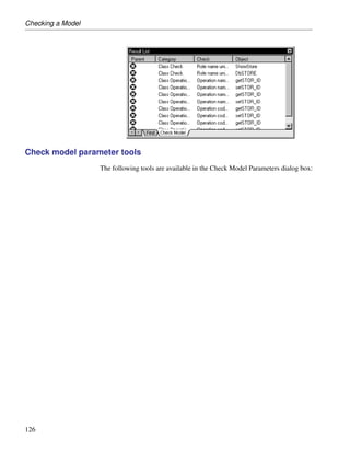
The Check Model Modeling Result List displays errors and warnings
based on the check options you have defined. For information about how
to correct errors, see “Correcting errors in the check model Modeling
Result List” on page 127.
125](https://image.slidesharecdn.com/eclipsepluginuserguide-110617230622-phpapp02/85/Eclipse-plugin-userguide-170-320.jpg)
![Chapter 4. Managing Models
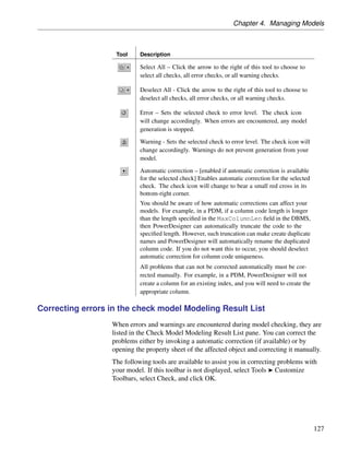
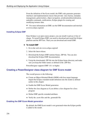
Tool Description
Select All – Click the arrow to the right of this tool to choose to
select all checks, all error checks, or all warning checks.
Deselect All - Click the arrow to the right of this tool to choose to
deselect all checks, all error checks, or all warning checks.
Error – Sets the selected check to error level. The check icon
will change accordingly. When errors are encountered, any model
generation is stopped.
Warning - Sets the selected check to error level. The check icon will
change accordingly. Warnings do not prevent generation from your
model.
Automatic correction – [enabled if automatic correction is available
for the selected check] Enables automatic correction for the selected
check. The check icon will change to bear a small red cross in its
bottom-right corner.
You should be aware of how automatic corrections can affect your
models. For example, in a PDM, if a column code length is longer
than the length specified in the MaxColumnLen field in the DBMS,
then PowerDesigner can automatically truncate the code to the
specified length. However, such truncation can make create duplicate
names and PowerDesigner will automatically rename the duplicated
column code. If you do not want this to occur, you should deselect
automatic correction for column code uniqueness.
All problems that can not be corrected automatically must be cor-
rected manually. For example, in a PDM, PowerDesigner will not
create a column for an existing index, and you will need to create the
appropriate column.
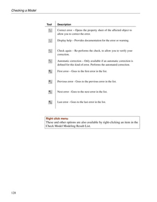
Correcting errors in the check model Modeling Result List
When errors and warnings are encountered during model checking, they are
listed in the Check Model Modeling Result List pane. You can correct the
problems either by invoking a automatic correction (if available) or by
opening the property sheet of the affected object and correcting it manually.
The following tools are available to assist you in correcting problems with
your model. If this toolbar is not displayed, select Tools ® Customize
Toolbars, select Check, and click OK.
127](https://image.slidesharecdn.com/eclipsepluginuserguide-110617230622-phpapp02/85/Eclipse-plugin-userguide-172-320.jpg)
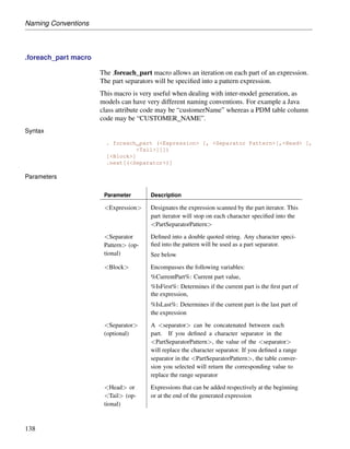
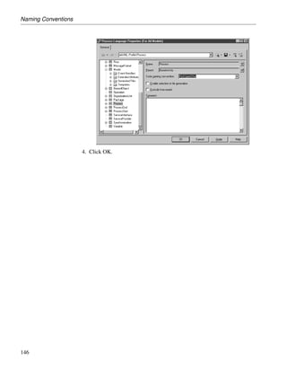
![Naming Conventions
.foreach_part macro
The .foreach_part macro allows an iteration on each part of an expression.
The part separators will be specified into a pattern expression.
This macro is very useful when dealing with inter-model generation, as
models can have very different naming conventions. For example a Java
class attribute code may be “customerName” whereas a PDM table column
code may be “CUSTOMER_NAME”.
Syntax
. foreach_part (<Expression> [, <Separator Pattern>[,<Head> [,
<Tail>]]])
[<Block>]
.next[(<Separator>)]
Parameters
Parameter Description
<Expression> Designates the expression scanned by the part iterator. This
part iterator will stop on each character specified into the
<PartSeparatorPattern>
<Separator Defined into a double quoted string. Any character speci-
Pattern> (op- fied into the pattern will be used as a part separator.
tional) See below
<Block> Encompasses the following variables:
%CurrentPart%: Current part value,
%IsFirst%: Determines if the current part is the first part of
the expression,
%IsLast%: Determines if the current part is the last part of
the expression
<Separator> A <separator> can be concatenated between each
(optional) part. If you defined a character separator in the
<PartSeparatorPattern>, the value of the <separator>
will replace the character separator. If you defined a range
separator in the <PartSeparatorPattern>, the table conver-
sion you selected will return the corresponding value to
replace the range separator
<Head> or Expressions that can be added respectively at the beginning
<Tail> (op- or at the end of the generated expression
tional)
138](https://image.slidesharecdn.com/eclipsepluginuserguide-110617230622-phpapp02/85/Eclipse-plugin-userguide-185-320.jpg)
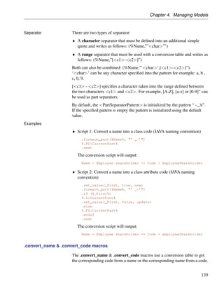
![Chapter 4. Managing Models
Separator There are two types of separator:
♦ A character separator that must be defined into an additional simple
quote and writes as follows: (%Name,”’<char>”’)
♦ A range separator that must be used with a conversion table and writes as
follows: (%Name,”[<c1>-<c2>]”)
Both can also be combined: (%Name,”’<char>’,[<c1>-<c2>]”).
‘<char>’ can be any character specified into the pattern for example: a, b ,
c, 0, 9.
[<c1> - <c2>] specifies a character taken into the range defined between
the two characters <c1> and <c2>. For example, [A-Z], [a-z] or [0-9]” can
be used as part separators.
By default, the <PartSeparatorPattern> is initialized by the pattern “ -_,t”.
If the specified pattern is empty the pattern is initialized using the default
value.
Examples
♦ Script 1: Convert a name into a class code (JAVA naming convention)
.foreach_part(%Name%, "’ _-’")
%.FU:CurrentPart%
.next
The conversion script will output:
Name = Employee shareholder => Code = EmployeeShareholder
♦ Script 2: Convert a name into a class attribute code (JAVA naming
convention)
.set_value(_First, true, new)
.foreach_part(%Name%, "’ _-’")
.if (%_First%)
%.L:CurrentPart%
.set_value(_First, false, update)
.else
%.FU:CurrentPart%
.endif
.next
The conversion script will output:
Name = Employee shareholder => Code = employeeShareholder
.convert_name & .convert_code macros
The .convert_name & .convert_code macros use a conversion table to get
the corresponding code from a name or the corresponding name from a code.
139](https://image.slidesharecdn.com/eclipsepluginuserguide-110617230622-phpapp02/85/Eclipse-plugin-userguide-186-320.jpg)
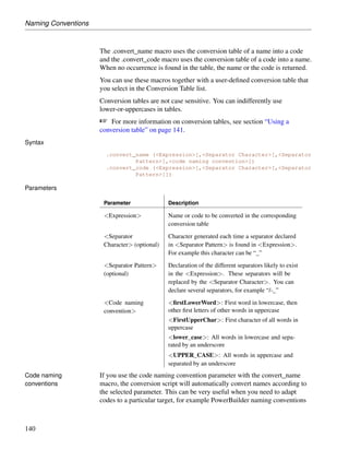
![For more information on conversion tables, see section “Using a
conversion table” on page 141.
Syntax
.convert_name (<Expression>[,<Separator Character>[,<Separator
Pattern>],<code naming convention>])
.convert_code (<Expression>[,<Separator Character>[,<Separator
Pattern>]])
Parameters
Parameter Description
<Expression> Name or code to be converted in the corresponding
conversion table
<Separator Character generated each time a separator declared
Character> (optional) in <Separator Pattern> is found in <Expression>.
For example this character can be “_”
<Separator Pattern> Declaration of the different separators likely to exist
(optional) in the <Expression>. These separators will be
replaced by the <Separator Character>. You can
declare several separators, for example “/-_”
<Code naming <firstLowerWord>: First word in lowercase, then
convention> other first letters of other words in uppercase
<FirstUpperChar>: First character of all words in
uppercase
<lower_case>: All words in lowercase and sepa-
rated by an underscore
<UPPER_CASE>: All words in uppercase and
separated by an underscore
Code naming If you use the code naming convention parameter with the convert_name
conventions macro, the conversion script will automatically convert names according to
the selected parameter. This can be very useful when you need to adapt
codes to a particular target, for example PowerBuilder naming conventions
140](https://image.slidesharecdn.com/eclipsepluginuserguide-110617230622-phpapp02/85/Eclipse-plugin-userguide-188-320.jpg)
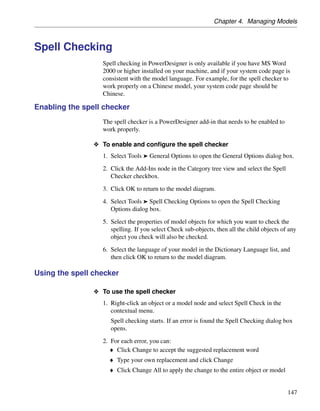
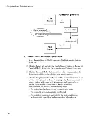
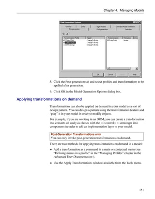
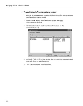
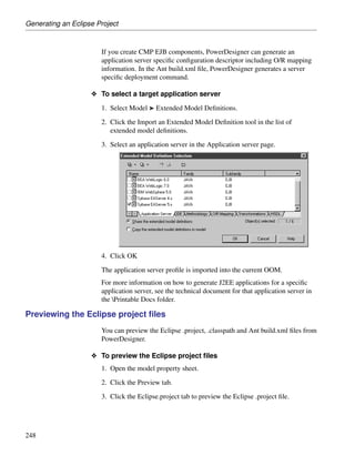
![Applying Model Transformations
O To use the Apply Transformations window
1. Add one or more extended model definitions containing post-generation
transformations to your model
2. Select Tools ® Apply Transformations to open the Apply
Transformations window.
3. Select transformations profiles and transformations on the
Transformations tab.
4. [optional] Click the Selection tab and deselect any objects that you want
to exclude from the transformation.
5. Click OK to apply the transformations.
152](https://image.slidesharecdn.com/eclipsepluginuserguide-110617230622-phpapp02/85/Eclipse-plugin-userguide-202-320.jpg)

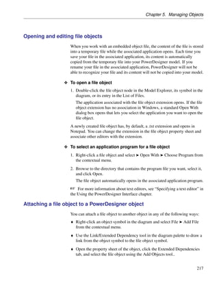
![Defining Objects
3. Double-click the new link object symbol in the diagram to display the
link object property sheet.
4. Type a link object name and code.
5. Click OK to return to the model diagram.
Complete links The Complete Links command available from the Tools menu allows you to
display the symbols of links existing in the model. If you select objects in
the diagram, the Complete Links command only applies to these objects.
Creating an object from the Model Explorer
You can create objects from the Model Explorer. Link objects can be created
from the Model Explorer only if you have previously defined the required
source and destination objects.
O To create an object from the Model Explorer
1. Right-click a model, package or an object category in the Model
Explorer, and select New ® object type from the contextual menu.
The object is created and its property sheet opens.
2. Type an object name and an object code.
3. [for link objects] Select a source and a destination object.
4. Click OK.
The object node is displayed under its corresponding category in the
Model Explorer.
Associated symbol in diagram
By default, when you create an object from the Model Explorer, it does
not have a symbol. You can create a symbol for the newly created object
by pressing the SHIFT key and dragging and dropping the node into the
diagram window.
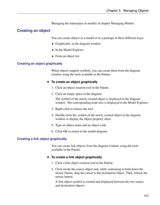
Creating an object in an object list
You can create an object in an object list. Link objects can be created in a list
of objects only if you have previously defined the required source and
destination objects.
164](https://image.slidesharecdn.com/eclipsepluginuserguide-110617230622-phpapp02/85/Eclipse-plugin-userguide-215-320.jpg)
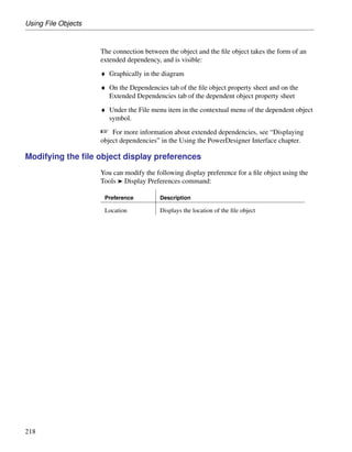
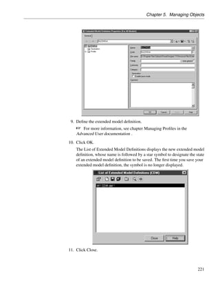
![Chapter 5. Managing Objects
O To create an object in a list of objects
1. Select Model ® object list to open the appropriate object list.
2. Click the Add a Row tool.
or
Click an empty line in the list.
or
[if the list is ordered] Click the Insert a row tool, .
A new item is added at the end of the list or before the selected row in the
list.
3. Type an object name and an object code.
4. [for link objects] Select a source and a destination object.
5. Click OK.
Associated symbol in diagram
By default, when you create an object in a list of objects, the symbol of
the new object is displayed in the current diagram.](https://image.slidesharecdn.com/eclipsepluginuserguide-110617230622-phpapp02/85/Eclipse-plugin-userguide-216-320.jpg)
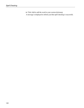
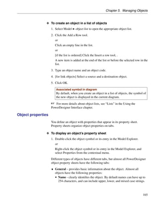
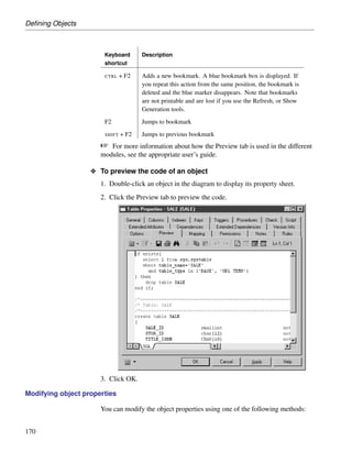
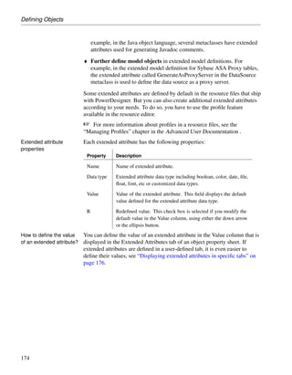
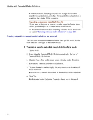
![Defining Objects
• Code – is a reference for the object. It is used in scripts that are
generated from the model. By default, codes can have up to 254
characters, and can include upper, lower, and mixed case strings.
• Comment – [optional] provides a more detailed description of the
object. You can display (and edit) object comments on their many
diagram symbols using the “Comment” Display Preference. This
feature can be useful when importing an ERwin model into a CDM or
PDM.
♦ Notes – lists additional information about the object. For more
information, see “Attaching notes to an object” on page 166.
♦ Rules – lists the business rules that the system must follow. A business
rule could be a government-imposed law, a customer requirement, or an
internal guideline. For more information, see “Business Rules” on
page 178.
♦ Version Info - provides details about the object owner, creation, and
modification date.
♦ Dependencies - lists all the objects that depend on the object
♦ Extended dependencies - lists all the objects on which the object
depends
Navigating between tabs
Use CTRL + PAGE DOWN or CTRL + PAGE UP to move to the next or to the
previous tab and display the corresponding object type tab.
Opening property sheets at last accessed tab
Property sheets open to the General tab by default. However, you can
choose to open property sheets at the last accessed tab by selecting Tools
® General Options ® Dialog, and selecting the Keep Last Tab option in the
Property Sheets groupbox.
Attaching notes to an object
♦ The Notes tab in an object property sheet contains two sub-tabs:
• Descriptions - in general, includes important information that does not
fit into the General tab. For example, a description of the Employee
entity might read: This entity has one occurrence for each employee in
our worldwide operations. This base should grow by 20 percent in
2002.
166](https://image.slidesharecdn.com/eclipsepluginuserguide-110617230622-phpapp02/85/Eclipse-plugin-userguide-218-320.jpg)
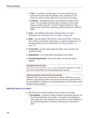
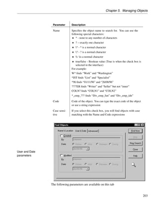
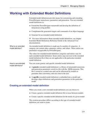
![Chapter 5. Managing Objects
• Annotations - contains notes regarding the implementation of a model
or the objects it contains. For example, an annotation of the Employee
entity might read: Verify list of attributes with Director of Human
Resources.
Both are editable directly in the tab with the internal PowerDesigner RTF
editor, which includes the following tools:
Tool Description
[ SHIFT + F11] Open Editor Menu.
For more information, see “Working with free text” in the Model
Graphics chapter.
[C TRL + E] Edit With. Opens your default RTF editor you previ-
ously defined or allows you to select another editor if you click the
down arrow beside this tool.](https://image.slidesharecdn.com/eclipsepluginuserguide-110617230622-phpapp02/85/Eclipse-plugin-userguide-219-320.jpg)
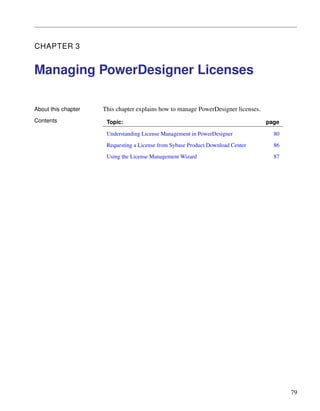
![Business Rules
Property Description
Type Specifies the nature of the business rule. You can choose
between:
♦ Constraint – a check constraint on a value. In a PDM,
constraint business rules can be generated in the database.
For example, “The start date should be inferior to the end
date of a project.”
♦ Definition – a property of the element in the system. For
example; “A customer is a person identified by a name and
an address”.
♦ Fact – a certainty in the system. For example, “A client
may place one or more orders”.
♦ Formula – a calculation. For example, “The total order is
the sum of all the order line costs”.
♦ OCL constraint [OOM only] – An Object Constraint Lan-
guage expression. See “Business rule property sheet OCL
Constraint tab” on page 180.
♦ Requirement – a functional specification. For example,
“The model is designed so that total losses do not exceed
10% of total sales”.
♦ Validation – a constraint on a value. For example, “The
sum of all orders for a client must not be greater than that
client’s allowance”.
Business rule property sheet Expression tab
A business rule typically starts out as a description. As you develop your
model and analyze your business problem, you can complete a rule by
adding a technical expression. Expressions are used primarily in CDMs and
PDMs.
Each business rule can include two types of expression, which you define on
the appropriate sub-tab:
♦ Server
♦ Client
Business rule property sheet OCL Constraint tab
This tab is only available for business rules with a type of OCL Constraint.
The Object Constraint Language is the UML expression language. Enter
180](https://image.slidesharecdn.com/eclipsepluginuserguide-110617230622-phpapp02/85/Eclipse-plugin-userguide-238-320.jpg)
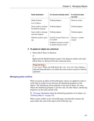
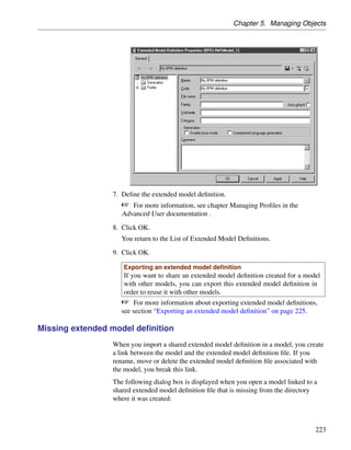
![Chapter 5. Managing Objects
Deleting domains and data items in a CDM or PDM
If you have specified that domains and data items can be reused by multiple
objects in a CDM or PDM and you delete a parent object to which they
belong, these sub-objects will not be deleted with their parent. For more
information, see the Conceptual Data Model and Physical Data Model
User’s Guides.
O To delete an object from the Model Explorer
1. Select the object node in the Model Explorer and press the DEL key.
or
Right-click the object node in the Model Explorer and select Edit ®
Delete from the contextual menu.
The Confirmation dialog box is displayed.
2. [optional] Click the Impact button to evaluate the impact of the deletion
(see the Impact Analysis chapter).
3. Click OK.
The object, its symbol, and any sub-objects are deleted from the model.
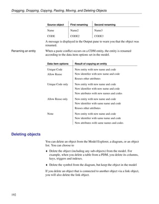
O To delete an object from the diagram window
1. Select the object symbol in the diagram and press the DEL key.
or
Right-click the object symbol in the diagram and select Edit ® Delete
from the contextual menu.
The Confirm Deletion dialog box is displayed. Note that if you delete a
free symbol, such as free text, a line or a shape, no confirmation is
required.
193](https://image.slidesharecdn.com/eclipsepluginuserguide-110617230622-phpapp02/85/Eclipse-plugin-userguide-260-320.jpg)
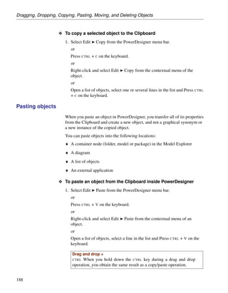
![Dragging, Dropping, Copying, Pasting, Moving, and Deleting Objects
2. [optional] Click the Impact button to evaluate the impact of the deletion
(see the Impact Analysis chapter).
3. Choose one of the following delete options:
♦ Delete objects – deletes the object, with all its properties and
sub-objects from the model
♦ Delete symbols only – deletes the object symbol from the diagram, but
leaves the object available in the model for future use
4. Click OK.
The object (or only its symbol) is deleted from the model.
O To delete an object from a list
1. Select Model ® Object to display a list of objects.
2. Select one or more items in the list and then click the Delete button.
No confirmation dialog box opens. The object is deleted directed from
the model.
3. Click OK to close the list and return to the model diagram.
Undo deletion
You can select Edit ® Undo to undo the deletion. You can restore the
symbol in the diagram, by selecting Symbol ® Show Symbols and selecting
the object’s check box in the Show Symbols dialog box.
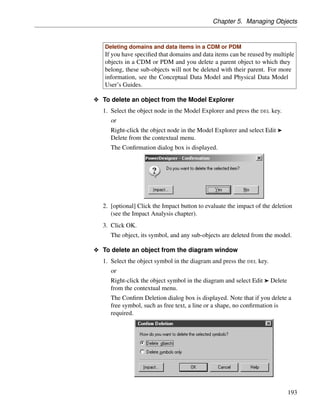
Suppressing the delete confirmation dialog box
By default, you are required to confirm any deletion of an object. You can
suppress these confirmation messages.
194](https://image.slidesharecdn.com/eclipsepluginuserguide-110617230622-phpapp02/85/Eclipse-plugin-userguide-261-320.jpg)

![Using File Objects
Property Description
Stereo- Sub-classification used to extend the semantics of the file object.
type You can create stereotypes in the Profile category of the resource
file attached to the current model.
Location Specifies the nature of the file object. You can choose from the
type following options:
♦ Embedded – the file is stored within the model and is saved
when you save the model.
♦ External – the file is stored in the Windows file system, and
you must enter its path in the Location field.
♦ URL – the file is on the web and you must enter its URL in
the Location field
If you subsequently change the type:
♦ From external to embedded – you will be prompted to import
the contents of the file into the model
♦ From embedded to external – you will be warned that the
existing contents will be lost.
Location [External and URL types only] Path or URL to the file.
Extension Extension of the file object name that indicates the application
to open when the file object is embedded
Generate File object is automatically included among the objects gener-
ated from the model when you launch the inter-model generation
process
Artifact Specifies that the file object is not a piece of documentation, but
rather forms an integral part of the application.
If an artifact has an extension that is defined in the Editors
page in the General Options dialog box and is linked to the
<internal> editor (see “Specifying text editors” in the Using the
PowerDesigner Interface chapter), a Contents tab is displayed
in the artifact property sheet. The Contents tab allows you
to edit the artifact file directly in the internal text editor of
PowerDesigner.
For more information about the use of artifact files, see “Files”
in the Building Physical Diagrams chapter of the OOM User’s
Guide .
216](https://image.slidesharecdn.com/eclipsepluginuserguide-110617230622-phpapp02/85/Eclipse-plugin-userguide-285-320.jpg)


![Wp br v7_a_vmware_architects_favorite_features[1]](https://cdn.slidesharecdn.com/ss_thumbnails/wpbrv7avmwarearchitectsfavoritefeatures1-131003071359-phpapp01-thumbnail.jpg?width=640&height=640&fit=bounds)